EP0977094B1 - Träger für die Entwicklung elektrostatischer latenter Bilder und diesen Träger benutzendes Bildherstellungsgerät - Google Patents
Träger für die Entwicklung elektrostatischer latenter Bilder und diesen Träger benutzendes Bildherstellungsgerät Download PDFInfo
- Publication number
- EP0977094B1 EP0977094B1 EP99114620A EP99114620A EP0977094B1 EP 0977094 B1 EP0977094 B1 EP 0977094B1 EP 99114620 A EP99114620 A EP 99114620A EP 99114620 A EP99114620 A EP 99114620A EP 0977094 B1 EP0977094 B1 EP 0977094B1
- Authority
- EP
- European Patent Office
- Prior art keywords
- carrier
- particles
- weight
- resin
- toner
- Prior art date
- Legal status (The legal status is an assumption and is not a legal conclusion. Google has not performed a legal analysis and makes no representation as to the accuracy of the status listed.)
- Expired - Lifetime
Links
- 238000011161 development Methods 0.000 title claims description 14
- 239000002245 particle Substances 0.000 claims description 164
- 229920005989 resin Polymers 0.000 claims description 135
- 239000011347 resin Substances 0.000 claims description 135
- 239000011248 coating agent Substances 0.000 claims description 89
- 238000000576 coating method Methods 0.000 claims description 89
- 239000000696 magnetic material Substances 0.000 claims description 60
- 238000004140 cleaning Methods 0.000 claims description 59
- 229920006395 saturated elastomer Polymers 0.000 claims description 13
- 108091008695 photoreceptors Proteins 0.000 claims description 12
- 229920005992 thermoplastic resin Polymers 0.000 claims description 11
- 238000012360 testing method Methods 0.000 claims description 9
- 229910021417 amorphous silicon Inorganic materials 0.000 claims description 7
- 238000012546 transfer Methods 0.000 claims description 5
- YXFVVABEGXRONW-UHFFFAOYSA-N Toluene Chemical compound CC1=CC=CC=C1 YXFVVABEGXRONW-UHFFFAOYSA-N 0.000 description 30
- 238000000034 method Methods 0.000 description 29
- NIXOWILDQLNWCW-UHFFFAOYSA-M Acrylate Chemical compound [O-]C(=O)C=C NIXOWILDQLNWCW-UHFFFAOYSA-M 0.000 description 23
- -1 polyethylene Polymers 0.000 description 19
- 239000000969 carrier Substances 0.000 description 16
- 230000000704 physical effect Effects 0.000 description 14
- 230000000052 comparative effect Effects 0.000 description 13
- 206010040844 Skin exfoliation Diseases 0.000 description 12
- 239000000463 material Substances 0.000 description 11
- 230000002035 prolonged effect Effects 0.000 description 10
- VYPSYNLAJGMNEJ-UHFFFAOYSA-N Silicium dioxide Chemical compound O=[Si]=O VYPSYNLAJGMNEJ-UHFFFAOYSA-N 0.000 description 9
- 239000011230 binding agent Substances 0.000 description 9
- 239000003795 chemical substances by application Substances 0.000 description 9
- SZVJSHCCFOBDDC-UHFFFAOYSA-N iron(II,III) oxide Inorganic materials O=[Fe]O[Fe]O[Fe]=O SZVJSHCCFOBDDC-UHFFFAOYSA-N 0.000 description 9
- OKTJSMMVPCPJKN-UHFFFAOYSA-N Carbon Chemical compound [C] OKTJSMMVPCPJKN-UHFFFAOYSA-N 0.000 description 8
- 238000005259 measurement Methods 0.000 description 8
- 239000000178 monomer Substances 0.000 description 8
- VVQNEPGJFQJSBK-UHFFFAOYSA-N Methyl methacrylate Chemical compound COC(=O)C(C)=C VVQNEPGJFQJSBK-UHFFFAOYSA-N 0.000 description 7
- 229920006026 co-polymeric resin Polymers 0.000 description 7
- 238000011109 contamination Methods 0.000 description 7
- 239000000203 mixture Substances 0.000 description 7
- 239000000049 pigment Substances 0.000 description 7
- 229920001169 thermoplastic Polymers 0.000 description 7
- 239000004416 thermosoftening plastic Substances 0.000 description 7
- XEEYBQQBJWHFJM-UHFFFAOYSA-N Iron Chemical compound [Fe] XEEYBQQBJWHFJM-UHFFFAOYSA-N 0.000 description 6
- 229910001289 Manganese-zinc ferrite Inorganic materials 0.000 description 6
- JIYIUPFAJUGHNL-UHFFFAOYSA-N [O--].[O--].[O--].[O--].[O--].[O--].[O--].[O--].[O--].[O--].[O--].[O--].[O--].[O--].[O--].[O--].[O--].[O--].[O--].[O--].[Mn++].[Mn++].[Mn++].[Fe+3].[Fe+3].[Fe+3].[Fe+3].[Fe+3].[Fe+3].[Fe+3].[Fe+3].[Fe+3].[Fe+3].[Zn++].[Zn++] Chemical compound [O--].[O--].[O--].[O--].[O--].[O--].[O--].[O--].[O--].[O--].[O--].[O--].[O--].[O--].[O--].[O--].[O--].[O--].[O--].[O--].[Mn++].[Mn++].[Mn++].[Fe+3].[Fe+3].[Fe+3].[Fe+3].[Fe+3].[Fe+3].[Fe+3].[Fe+3].[Fe+3].[Fe+3].[Zn++].[Zn++] JIYIUPFAJUGHNL-UHFFFAOYSA-N 0.000 description 6
- 239000006247 magnetic powder Substances 0.000 description 6
- TWNQGVIAIRXVLR-UHFFFAOYSA-N oxo(oxoalumanyloxy)alumane Chemical compound O=[Al]O[Al]=O TWNQGVIAIRXVLR-UHFFFAOYSA-N 0.000 description 6
- 238000003825 pressing Methods 0.000 description 6
- 239000002904 solvent Substances 0.000 description 6
- 229920001187 thermosetting polymer Polymers 0.000 description 6
- 229920000178 Acrylic resin Polymers 0.000 description 5
- 239000004925 Acrylic resin Substances 0.000 description 5
- MCMNRKCIXSYSNV-UHFFFAOYSA-N Zirconium dioxide Chemical compound O=[Zr]=O MCMNRKCIXSYSNV-UHFFFAOYSA-N 0.000 description 5
- 125000004432 carbon atom Chemical group C* 0.000 description 5
- 238000007334 copolymerization reaction Methods 0.000 description 5
- 239000006185 dispersion Substances 0.000 description 5
- JEIPFZHSYJVQDO-UHFFFAOYSA-N ferric oxide Chemical compound O=[Fe]O[Fe]=O JEIPFZHSYJVQDO-UHFFFAOYSA-N 0.000 description 5
- 239000007788 liquid Substances 0.000 description 5
- PXHVJJICTQNCMI-UHFFFAOYSA-N Nickel Chemical compound [Ni] PXHVJJICTQNCMI-UHFFFAOYSA-N 0.000 description 4
- KKEYFWRCBNTPAC-UHFFFAOYSA-N Terephthalic acid Chemical compound OC(=O)C1=CC=C(C(O)=O)C=C1 KKEYFWRCBNTPAC-UHFFFAOYSA-N 0.000 description 4
- 229910052799 carbon Inorganic materials 0.000 description 4
- 239000012530 fluid Substances 0.000 description 4
- UQSXHKLRYXJYBZ-UHFFFAOYSA-N iron oxide Inorganic materials [Fe]=O UQSXHKLRYXJYBZ-UHFFFAOYSA-N 0.000 description 4
- 230000005415 magnetization Effects 0.000 description 4
- 229920001225 polyester resin Polymers 0.000 description 4
- 239000004645 polyester resin Substances 0.000 description 4
- 230000008569 process Effects 0.000 description 4
- 239000000377 silicon dioxide Substances 0.000 description 4
- 125000006850 spacer group Chemical group 0.000 description 4
- DTGKSKDOIYIVQL-WEDXCCLWSA-N (+)-borneol Chemical group C1C[C@@]2(C)[C@@H](O)C[C@@H]1C2(C)C DTGKSKDOIYIVQL-WEDXCCLWSA-N 0.000 description 3
- ZWEHNKRNPOVVGH-UHFFFAOYSA-N 2-Butanone Chemical compound CCC(C)=O ZWEHNKRNPOVVGH-UHFFFAOYSA-N 0.000 description 3
- CSCPPACGZOOCGX-UHFFFAOYSA-N Acetone Chemical compound CC(C)=O CSCPPACGZOOCGX-UHFFFAOYSA-N 0.000 description 3
- LFQSCWFLJHTTHZ-UHFFFAOYSA-N Ethanol Chemical compound CCO LFQSCWFLJHTTHZ-UHFFFAOYSA-N 0.000 description 3
- XEKOWRVHYACXOJ-UHFFFAOYSA-N Ethyl acetate Chemical compound CCOC(C)=O XEKOWRVHYACXOJ-UHFFFAOYSA-N 0.000 description 3
- LYCAIKOWRPUZTN-UHFFFAOYSA-N Ethylene glycol Chemical compound OCCO LYCAIKOWRPUZTN-UHFFFAOYSA-N 0.000 description 3
- ZMXDDKWLCZADIW-UHFFFAOYSA-N N,N-Dimethylformamide Chemical compound CN(C)C=O ZMXDDKWLCZADIW-UHFFFAOYSA-N 0.000 description 3
- 239000004743 Polypropylene Substances 0.000 description 3
- XLOMVQKBTHCTTD-UHFFFAOYSA-N Zinc monoxide Chemical compound [Zn]=O XLOMVQKBTHCTTD-UHFFFAOYSA-N 0.000 description 3
- 125000000217 alkyl group Chemical group 0.000 description 3
- 229910045601 alloy Inorganic materials 0.000 description 3
- 239000000956 alloy Substances 0.000 description 3
- 125000000129 anionic group Chemical group 0.000 description 3
- 230000015572 biosynthetic process Effects 0.000 description 3
- 125000002091 cationic group Chemical group 0.000 description 3
- GUTLYIVDDKVIGB-UHFFFAOYSA-N cobalt atom Chemical compound [Co] GUTLYIVDDKVIGB-UHFFFAOYSA-N 0.000 description 3
- XCJYREBRNVKWGJ-UHFFFAOYSA-N copper(II) phthalocyanine Chemical compound [Cu+2].C12=CC=CC=C2C(N=C2[N-]C(C3=CC=CC=C32)=N2)=NC1=NC([C]1C=CC=CC1=1)=NC=1N=C1[C]3C=CC=CC3=C2[N-]1 XCJYREBRNVKWGJ-UHFFFAOYSA-N 0.000 description 3
- QDOXWKRWXJOMAK-UHFFFAOYSA-N dichromium trioxide Chemical compound O=[Cr]O[Cr]=O QDOXWKRWXJOMAK-UHFFFAOYSA-N 0.000 description 3
- 229920001971 elastomer Polymers 0.000 description 3
- 239000010419 fine particle Substances 0.000 description 3
- 125000000959 isobutyl group Chemical group [H]C([H])([H])C([H])(C([H])([H])[H])C([H])([H])* 0.000 description 3
- 238000002955 isolation Methods 0.000 description 3
- 230000007246 mechanism Effects 0.000 description 3
- 229920005672 polyolefin resin Polymers 0.000 description 3
- 229920001155 polypropylene Polymers 0.000 description 3
- 238000010298 pulverizing process Methods 0.000 description 3
- 238000005507 spraying Methods 0.000 description 3
- 239000000126 substance Substances 0.000 description 3
- 229920002554 vinyl polymer Polymers 0.000 description 3
- OSNILPMOSNGHLC-UHFFFAOYSA-N 1-[4-methoxy-3-(piperidin-1-ylmethyl)phenyl]ethanone Chemical compound COC1=CC=C(C(C)=O)C=C1CN1CCCCC1 OSNILPMOSNGHLC-UHFFFAOYSA-N 0.000 description 2
- ZNQVEEAIQZEUHB-UHFFFAOYSA-N 2-ethoxyethanol Chemical compound CCOCCO ZNQVEEAIQZEUHB-UHFFFAOYSA-N 0.000 description 2
- CERQOIWHTDAKMF-UHFFFAOYSA-M Methacrylate Chemical compound CC(=C)C([O-])=O CERQOIWHTDAKMF-UHFFFAOYSA-M 0.000 description 2
- LRHPLDYGYMQRHN-UHFFFAOYSA-N N-Butanol Chemical compound CCCCO LRHPLDYGYMQRHN-UHFFFAOYSA-N 0.000 description 2
- 239000004698 Polyethylene Substances 0.000 description 2
- 239000004793 Polystyrene Substances 0.000 description 2
- BLRPTPMANUNPDV-UHFFFAOYSA-N Silane Chemical compound [SiH4] BLRPTPMANUNPDV-UHFFFAOYSA-N 0.000 description 2
- WYURNTSHIVDZCO-UHFFFAOYSA-N Tetrahydrofuran Chemical compound C1CCOC1 WYURNTSHIVDZCO-UHFFFAOYSA-N 0.000 description 2
- GWEVSGVZZGPLCZ-UHFFFAOYSA-N Titan oxide Chemical compound O=[Ti]=O GWEVSGVZZGPLCZ-UHFFFAOYSA-N 0.000 description 2
- RTAQQCXQSZGOHL-UHFFFAOYSA-N Titanium Chemical compound [Ti] RTAQQCXQSZGOHL-UHFFFAOYSA-N 0.000 description 2
- 239000006230 acetylene black Substances 0.000 description 2
- XECAHXYUAAWDEL-UHFFFAOYSA-N acrylonitrile butadiene styrene Chemical compound C=CC=C.C=CC#N.C=CC1=CC=CC=C1 XECAHXYUAAWDEL-UHFFFAOYSA-N 0.000 description 2
- 229920000122 acrylonitrile butadiene styrene Polymers 0.000 description 2
- 239000004676 acrylonitrile butadiene styrene Substances 0.000 description 2
- 125000002723 alicyclic group Chemical group 0.000 description 2
- 239000006229 carbon black Substances 0.000 description 2
- 229910017052 cobalt Inorganic materials 0.000 description 2
- 239000010941 cobalt Substances 0.000 description 2
- 239000003086 colorant Substances 0.000 description 2
- 239000000470 constituent Substances 0.000 description 2
- 229920001577 copolymer Polymers 0.000 description 2
- 125000000113 cyclohexyl group Chemical group [H]C1([H])C([H])([H])C([H])([H])C([H])(*)C([H])([H])C1([H])[H] 0.000 description 2
- 125000003438 dodecyl group Chemical group [H]C([H])([H])C([H])([H])C([H])([H])C([H])([H])C([H])([H])C([H])([H])C([H])([H])C([H])([H])C([H])([H])C([H])([H])C([H])([H])C([H])([H])* 0.000 description 2
- 238000001035 drying Methods 0.000 description 2
- 239000003822 epoxy resin Substances 0.000 description 2
- 125000001495 ethyl group Chemical group [H]C([H])([H])C([H])([H])* 0.000 description 2
- 239000011737 fluorine Substances 0.000 description 2
- 229910052731 fluorine Inorganic materials 0.000 description 2
- 150000002430 hydrocarbons Chemical group 0.000 description 2
- 230000002209 hydrophobic effect Effects 0.000 description 2
- 229910052742 iron Inorganic materials 0.000 description 2
- 239000011572 manganese Substances 0.000 description 2
- 125000002496 methyl group Chemical group [H]C([H])([H])* 0.000 description 2
- 239000005011 phenolic resin Substances 0.000 description 2
- 229920000647 polyepoxide Polymers 0.000 description 2
- 229920000573 polyethylene Polymers 0.000 description 2
- 229920002223 polystyrene Polymers 0.000 description 2
- 229920000915 polyvinyl chloride Polymers 0.000 description 2
- 239000004800 polyvinyl chloride Substances 0.000 description 2
- 239000000843 powder Substances 0.000 description 2
- 150000003242 quaternary ammonium salts Chemical class 0.000 description 2
- 239000011342 resin composition Substances 0.000 description 2
- 239000005060 rubber Substances 0.000 description 2
- 229910000077 silane Inorganic materials 0.000 description 2
- 229920002379 silicone rubber Polymers 0.000 description 2
- 238000001694 spray drying Methods 0.000 description 2
- 125000004079 stearyl group Chemical group [H]C([*])([H])C([H])([H])C([H])([H])C([H])([H])C([H])([H])C([H])([H])C([H])([H])C([H])([H])C([H])([H])C([H])([H])C([H])([H])C([H])([H])C([H])([H])C([H])([H])C([H])([H])C([H])([H])C([H])([H])C([H])([H])[H] 0.000 description 2
- 238000003756 stirring Methods 0.000 description 2
- 125000000999 tert-butyl group Chemical group [H]C([H])([H])C(*)(C([H])([H])[H])C([H])([H])[H] 0.000 description 2
- OGIDPMRJRNCKJF-UHFFFAOYSA-N titanium oxide Inorganic materials [Ti]=O OGIDPMRJRNCKJF-UHFFFAOYSA-N 0.000 description 2
- 125000000391 vinyl group Chemical group [H]C([*])=C([H])[H] 0.000 description 2
- 239000001993 wax Substances 0.000 description 2
- 239000011787 zinc oxide Substances 0.000 description 2
- 235000014692 zinc oxide Nutrition 0.000 description 2
- DNIAPMSPPWPWGF-GSVOUGTGSA-N (R)-(-)-Propylene glycol Chemical compound C[C@@H](O)CO DNIAPMSPPWPWGF-GSVOUGTGSA-N 0.000 description 1
- RYHBNJHYFVUHQT-UHFFFAOYSA-N 1,4-Dioxane Chemical compound C1COCCO1 RYHBNJHYFVUHQT-UHFFFAOYSA-N 0.000 description 1
- SMZOUWXMTYCWNB-UHFFFAOYSA-N 2-(2-methoxy-5-methylphenyl)ethanamine Chemical compound COC1=CC=C(C)C=C1CCN SMZOUWXMTYCWNB-UHFFFAOYSA-N 0.000 description 1
- FWLHAQYOFMQTHQ-UHFFFAOYSA-N 2-N-[8-[[8-(4-aminoanilino)-10-phenylphenazin-10-ium-2-yl]amino]-10-phenylphenazin-10-ium-2-yl]-8-N,10-diphenylphenazin-10-ium-2,8-diamine hydroxy-oxido-dioxochromium Chemical compound O[Cr]([O-])(=O)=O.O[Cr]([O-])(=O)=O.O[Cr]([O-])(=O)=O.Nc1ccc(Nc2ccc3nc4ccc(Nc5ccc6nc7ccc(Nc8ccc9nc%10ccc(Nc%11ccccc%11)cc%10[n+](-c%10ccccc%10)c9c8)cc7[n+](-c7ccccc7)c6c5)cc4[n+](-c4ccccc4)c3c2)cc1 FWLHAQYOFMQTHQ-UHFFFAOYSA-N 0.000 description 1
- NIXOWILDQLNWCW-UHFFFAOYSA-N 2-Propenoic acid Natural products OC(=O)C=C NIXOWILDQLNWCW-UHFFFAOYSA-N 0.000 description 1
- JFMYRCRXYIIGBB-UHFFFAOYSA-N 2-[(2,4-dichlorophenyl)diazenyl]-n-[4-[4-[[2-[(2,4-dichlorophenyl)diazenyl]-3-oxobutanoyl]amino]-3-methylphenyl]-2-methylphenyl]-3-oxobutanamide Chemical compound C=1C=C(C=2C=C(C)C(NC(=O)C(N=NC=3C(=CC(Cl)=CC=3)Cl)C(C)=O)=CC=2)C=C(C)C=1NC(=O)C(C(=O)C)N=NC1=CC=C(Cl)C=C1Cl JFMYRCRXYIIGBB-UHFFFAOYSA-N 0.000 description 1
- QTSNFLIDNYOATQ-UHFFFAOYSA-N 2-[(4-chloro-2-nitrophenyl)diazenyl]-n-(2-chlorophenyl)-3-oxobutanamide Chemical compound C=1C=CC=C(Cl)C=1NC(=O)C(C(=O)C)N=NC1=CC=C(Cl)C=C1[N+]([O-])=O QTSNFLIDNYOATQ-UHFFFAOYSA-N 0.000 description 1
- MFYSUUPKMDJYPF-UHFFFAOYSA-N 2-[(4-methyl-2-nitrophenyl)diazenyl]-3-oxo-n-phenylbutanamide Chemical compound C=1C=CC=CC=1NC(=O)C(C(=O)C)N=NC1=CC=C(C)C=C1[N+]([O-])=O MFYSUUPKMDJYPF-UHFFFAOYSA-N 0.000 description 1
- POAOYUHQDCAZBD-UHFFFAOYSA-N 2-butoxyethanol Chemical compound CCCCOCCO POAOYUHQDCAZBD-UHFFFAOYSA-N 0.000 description 1
- WUPHOULIZUERAE-UHFFFAOYSA-N 3-(oxolan-2-yl)propanoic acid Chemical compound OC(=O)CCC1CCCO1 WUPHOULIZUERAE-UHFFFAOYSA-N 0.000 description 1
- DWDURZSYQTXVIN-UHFFFAOYSA-N 4-[(4-aminophenyl)-(4-methyliminocyclohexa-2,5-dien-1-ylidene)methyl]aniline Chemical compound C1=CC(=NC)C=CC1=C(C=1C=CC(N)=CC=1)C1=CC=C(N)C=C1 DWDURZSYQTXVIN-UHFFFAOYSA-N 0.000 description 1
- LVOJOIBIVGEQBP-UHFFFAOYSA-N 4-[[2-chloro-4-[3-chloro-4-[(5-hydroxy-3-methyl-1-phenylpyrazol-4-yl)diazenyl]phenyl]phenyl]diazenyl]-5-methyl-2-phenylpyrazol-3-ol Chemical compound CC1=NN(C(O)=C1N=NC1=CC=C(C=C1Cl)C1=CC(Cl)=C(C=C1)N=NC1=C(O)N(N=C1C)C1=CC=CC=C1)C1=CC=CC=C1 LVOJOIBIVGEQBP-UHFFFAOYSA-N 0.000 description 1
- WSSSPWUEQFSQQG-UHFFFAOYSA-N 4-methyl-1-pentene Chemical compound CC(C)CC=C WSSSPWUEQFSQQG-UHFFFAOYSA-N 0.000 description 1
- 229910002012 Aerosil® Inorganic materials 0.000 description 1
- QGZKDVFQNNGYKY-UHFFFAOYSA-N Ammonia Chemical group N QGZKDVFQNNGYKY-UHFFFAOYSA-N 0.000 description 1
- 229910052582 BN Inorganic materials 0.000 description 1
- 229910002771 BaFe12O19 Inorganic materials 0.000 description 1
- LSNNMFCWUKXFEE-UHFFFAOYSA-M Bisulfite Chemical group OS([O-])=O LSNNMFCWUKXFEE-UHFFFAOYSA-M 0.000 description 1
- PZNSFCLAULLKQX-UHFFFAOYSA-N Boron nitride Chemical compound N#B PZNSFCLAULLKQX-UHFFFAOYSA-N 0.000 description 1
- DKPFZGUDAPQIHT-UHFFFAOYSA-N Butyl acetate Natural products CCCCOC(C)=O DKPFZGUDAPQIHT-UHFFFAOYSA-N 0.000 description 1
- REEFSLKDEDEWAO-UHFFFAOYSA-N Chloraniformethan Chemical compound ClC1=CC=C(NC(NC=O)C(Cl)(Cl)Cl)C=C1Cl REEFSLKDEDEWAO-UHFFFAOYSA-N 0.000 description 1
- VEXZGXHMUGYJMC-UHFFFAOYSA-M Chloride anion Chemical compound [Cl-] VEXZGXHMUGYJMC-UHFFFAOYSA-M 0.000 description 1
- 241000557626 Corvus corax Species 0.000 description 1
- 229910016516 CuFe2O4 Inorganic materials 0.000 description 1
- XDTMQSROBMDMFD-UHFFFAOYSA-N Cyclohexane Chemical compound C1CCCCC1 XDTMQSROBMDMFD-UHFFFAOYSA-N 0.000 description 1
- PXGOKWXKJXAPGV-UHFFFAOYSA-N Fluorine Chemical compound FF PXGOKWXKJXAPGV-UHFFFAOYSA-N 0.000 description 1
- 229910002608 Gd3Fe5O12 Inorganic materials 0.000 description 1
- UFHFLCQGNIYNRP-UHFFFAOYSA-N Hydrogen Chemical compound [H][H] UFHFLCQGNIYNRP-UHFFFAOYSA-N 0.000 description 1
- 229910002321 LaFeO3 Inorganic materials 0.000 description 1
- CERQOIWHTDAKMF-UHFFFAOYSA-N Methacrylic acid Chemical compound CC(=C)C(O)=O CERQOIWHTDAKMF-UHFFFAOYSA-N 0.000 description 1
- NTIZESTWPVYFNL-UHFFFAOYSA-N Methyl isobutyl ketone Chemical compound CC(C)CC(C)=O NTIZESTWPVYFNL-UHFFFAOYSA-N 0.000 description 1
- UIHCLUNTQKBZGK-UHFFFAOYSA-N Methyl isobutyl ketone Natural products CCC(C)C(C)=O UIHCLUNTQKBZGK-UHFFFAOYSA-N 0.000 description 1
- FXHOOIRPVKKKFG-UHFFFAOYSA-N N,N-Dimethylacetamide Chemical compound CN(C)C(C)=O FXHOOIRPVKKKFG-UHFFFAOYSA-N 0.000 description 1
- 229910003264 NiFe2O4 Inorganic materials 0.000 description 1
- 229910001053 Nickel-zinc ferrite Inorganic materials 0.000 description 1
- CTQNGGLPUBDAKN-UHFFFAOYSA-N O-Xylene Chemical compound CC1=CC=CC=C1C CTQNGGLPUBDAKN-UHFFFAOYSA-N 0.000 description 1
- ABLZXFCXXLZCGV-UHFFFAOYSA-N Phosphorous acid Chemical group OP(O)=O ABLZXFCXXLZCGV-UHFFFAOYSA-N 0.000 description 1
- 239000004952 Polyamide Substances 0.000 description 1
- 239000005062 Polybutadiene Substances 0.000 description 1
- 239000004721 Polyphenylene oxide Substances 0.000 description 1
- 239000004372 Polyvinyl alcohol Substances 0.000 description 1
- 229920001328 Polyvinylidene chloride Polymers 0.000 description 1
- BUGBHKTXTAQXES-UHFFFAOYSA-N Selenium Chemical compound [Se] BUGBHKTXTAQXES-UHFFFAOYSA-N 0.000 description 1
- 239000006087 Silane Coupling Agent Substances 0.000 description 1
- 229910001035 Soft ferrite Inorganic materials 0.000 description 1
- 229910000831 Steel Inorganic materials 0.000 description 1
- NRTOMJZYCJJWKI-UHFFFAOYSA-N Titanium nitride Chemical compound [Ti]#N NRTOMJZYCJJWKI-UHFFFAOYSA-N 0.000 description 1
- WGLPBDUCMAPZCE-UHFFFAOYSA-N Trioxochromium Chemical compound O=[Cr](=O)=O WGLPBDUCMAPZCE-UHFFFAOYSA-N 0.000 description 1
- 229920001807 Urea-formaldehyde Polymers 0.000 description 1
- 229920006311 Urethane elastomer Polymers 0.000 description 1
- 229910009493 Y3Fe5O12 Inorganic materials 0.000 description 1
- 229910001308 Zinc ferrite Inorganic materials 0.000 description 1
- 239000005083 Zinc sulfide Substances 0.000 description 1
- JHNCXGXWSIOXSX-UHFFFAOYSA-N [Nd+3].[O-2].[Fe+2] Chemical compound [Nd+3].[O-2].[Fe+2] JHNCXGXWSIOXSX-UHFFFAOYSA-N 0.000 description 1
- NEKNPTMOEUCRLW-UHFFFAOYSA-N [O-2].[Fe+2].[Gd+3] Chemical compound [O-2].[Fe+2].[Gd+3] NEKNPTMOEUCRLW-UHFFFAOYSA-N 0.000 description 1
- GZHZIMFFZGAOGY-UHFFFAOYSA-N [O-2].[Fe+2].[La+3] Chemical compound [O-2].[Fe+2].[La+3] GZHZIMFFZGAOGY-UHFFFAOYSA-N 0.000 description 1
- WQHONKDTTOGZPR-UHFFFAOYSA-N [O-2].[O-2].[Mn+2].[Fe+2] Chemical compound [O-2].[O-2].[Mn+2].[Fe+2] WQHONKDTTOGZPR-UHFFFAOYSA-N 0.000 description 1
- XHCLAFWTIXFWPH-UHFFFAOYSA-N [O-2].[O-2].[O-2].[O-2].[O-2].[V+5].[V+5] Chemical compound [O-2].[O-2].[O-2].[O-2].[O-2].[V+5].[V+5] XHCLAFWTIXFWPH-UHFFFAOYSA-N 0.000 description 1
- AUNAPVYQLLNFOI-UHFFFAOYSA-L [Pb++].[Pb++].[Pb++].[O-]S([O-])(=O)=O.[O-][Cr]([O-])(=O)=O.[O-][Mo]([O-])(=O)=O Chemical compound [Pb++].[Pb++].[Pb++].[O-]S([O-])(=O)=O.[O-][Cr]([O-])(=O)=O.[O-][Mo]([O-])(=O)=O AUNAPVYQLLNFOI-UHFFFAOYSA-L 0.000 description 1
- LEVVHYCKPQWKOP-UHFFFAOYSA-N [Si].[Ge] Chemical compound [Si].[Ge] LEVVHYCKPQWKOP-UHFFFAOYSA-N 0.000 description 1
- HZEWFHLRYVTOIW-UHFFFAOYSA-N [Ti].[Ni] Chemical compound [Ti].[Ni] HZEWFHLRYVTOIW-UHFFFAOYSA-N 0.000 description 1
- 239000002253 acid Substances 0.000 description 1
- 230000009471 action Effects 0.000 description 1
- AOADSHDCARXSGL-ZMIIQOOPSA-M alkali blue 4B Chemical compound CC1=CC(/C(\C(C=C2)=CC=C2NC2=CC=CC=C2S([O-])(=O)=O)=C(\C=C2)/C=C/C\2=N\C2=CC=CC=C2)=CC=C1N.[Na+] AOADSHDCARXSGL-ZMIIQOOPSA-M 0.000 description 1
- PNEYBMLMFCGWSK-UHFFFAOYSA-N aluminium oxide Inorganic materials [O-2].[O-2].[O-2].[Al+3].[Al+3] PNEYBMLMFCGWSK-UHFFFAOYSA-N 0.000 description 1
- 125000003368 amide group Chemical group 0.000 description 1
- 150000001408 amides Chemical class 0.000 description 1
- GHPGOEFPKIHBNM-UHFFFAOYSA-N antimony(3+);oxygen(2-) Chemical compound [O-2].[O-2].[O-2].[Sb+3].[Sb+3] GHPGOEFPKIHBNM-UHFFFAOYSA-N 0.000 description 1
- 150000004945 aromatic hydrocarbons Chemical class 0.000 description 1
- 125000003118 aryl group Chemical group 0.000 description 1
- UHHXUPJJDHEMGX-UHFFFAOYSA-K azanium;manganese(3+);phosphonato phosphate Chemical compound [NH4+].[Mn+3].[O-]P([O-])(=O)OP([O-])([O-])=O UHHXUPJJDHEMGX-UHFFFAOYSA-K 0.000 description 1
- OVMJQLNJCSIJCH-UHFFFAOYSA-N azanylidyneneodymium Chemical compound [Nd]#N OVMJQLNJCSIJCH-UHFFFAOYSA-N 0.000 description 1
- QVQLCTNNEUAWMS-UHFFFAOYSA-N barium oxide Chemical compound [Ba]=O QVQLCTNNEUAWMS-UHFFFAOYSA-N 0.000 description 1
- WMDURRXBOBIUPJ-UHFFFAOYSA-N barium(2+) iron(2+) oxygen(2-) Chemical compound [Ba+2].[O-2].[Fe+2].[O-2] WMDURRXBOBIUPJ-UHFFFAOYSA-N 0.000 description 1
- AYJRCSIUFZENHW-DEQYMQKBSA-L barium(2+);oxomethanediolate Chemical compound [Ba+2].[O-][14C]([O-])=O AYJRCSIUFZENHW-DEQYMQKBSA-L 0.000 description 1
- 229910001864 baryta Inorganic materials 0.000 description 1
- 239000002585 base Substances 0.000 description 1
- 238000012661 block copolymerization Methods 0.000 description 1
- 239000001055 blue pigment Substances 0.000 description 1
- 125000000484 butyl group Chemical group [H]C([*])([H])C([H])([H])C([H])([H])C([H])([H])[H] 0.000 description 1
- 229910052793 cadmium Inorganic materials 0.000 description 1
- BDOSMKKIYDKNTQ-UHFFFAOYSA-N cadmium atom Chemical compound [Cd] BDOSMKKIYDKNTQ-UHFFFAOYSA-N 0.000 description 1
- CJOBVZJTOIVNNF-UHFFFAOYSA-N cadmium sulfide Chemical compound [Cd]=S CJOBVZJTOIVNNF-UHFFFAOYSA-N 0.000 description 1
- 229910052980 cadmium sulfide Inorganic materials 0.000 description 1
- BAXLMRUQFAMMQC-UHFFFAOYSA-N cadmium(2+) iron(2+) oxygen(2-) Chemical compound [Cd+2].[O-2].[Fe+2].[O-2] BAXLMRUQFAMMQC-UHFFFAOYSA-N 0.000 description 1
- YEYFPVZHOBESQQ-UHFFFAOYSA-N cadmium;sulfanylidenemercury Chemical compound [Cd].[Hg]=S YEYFPVZHOBESQQ-UHFFFAOYSA-N 0.000 description 1
- 159000000007 calcium salts Chemical class 0.000 description 1
- 125000003739 carbamimidoyl group Chemical group C(N)(=N)* 0.000 description 1
- 150000001732 carboxylic acid derivatives Chemical group 0.000 description 1
- 239000004203 carnauba wax Substances 0.000 description 1
- 235000013869 carnauba wax Nutrition 0.000 description 1
- 239000012461 cellulose resin Substances 0.000 description 1
- 150000004770 chalcogenides Chemical class 0.000 description 1
- HBHZKFOUIUMKHV-UHFFFAOYSA-N chembl1982121 Chemical compound OC1=CC=C2C=CC=CC2=C1N=NC1=CC=C([N+]([O-])=O)C=C1[N+]([O-])=O HBHZKFOUIUMKHV-UHFFFAOYSA-N 0.000 description 1
- PZTQVMXMKVTIRC-UHFFFAOYSA-L chembl2028348 Chemical compound [Ca+2].[O-]S(=O)(=O)C1=CC(C)=CC=C1N=NC1=C(O)C(C([O-])=O)=CC2=CC=CC=C12 PZTQVMXMKVTIRC-UHFFFAOYSA-L 0.000 description 1
- YOCIQNIEQYCORH-UHFFFAOYSA-M chembl2028361 Chemical compound [Na+].OC1=CC=C2C=C(S([O-])(=O)=O)C=CC2=C1N=NC1=CC=CC=C1 YOCIQNIEQYCORH-UHFFFAOYSA-M 0.000 description 1
- ZLFVRXUOSPRRKQ-UHFFFAOYSA-N chembl2138372 Chemical compound [O-][N+](=O)C1=CC(C)=CC=C1N=NC1=C(O)C=CC2=CC=CC=C12 ZLFVRXUOSPRRKQ-UHFFFAOYSA-N 0.000 description 1
- 229910000423 chromium oxide Inorganic materials 0.000 description 1
- 239000004927 clay Substances 0.000 description 1
- 229910052570 clay Inorganic materials 0.000 description 1
- 239000007859 condensation product Substances 0.000 description 1
- TVZPLCNGKSPOJA-UHFFFAOYSA-N copper zinc Chemical compound [Cu].[Zn] TVZPLCNGKSPOJA-UHFFFAOYSA-N 0.000 description 1
- CTQZMNHRQCCAJE-UHFFFAOYSA-N copper;iron(2+);oxygen(2-) Chemical compound [O-2].[O-2].[Fe+2].[Cu+2] CTQZMNHRQCCAJE-UHFFFAOYSA-N 0.000 description 1
- DXKGMXNZSJMWAF-UHFFFAOYSA-N copper;oxido(oxo)iron Chemical compound [Cu+2].[O-][Fe]=O.[O-][Fe]=O DXKGMXNZSJMWAF-UHFFFAOYSA-N 0.000 description 1
- 239000007822 coupling agent Substances 0.000 description 1
- 150000004292 cyclic ethers Chemical class 0.000 description 1
- 125000002704 decyl group Chemical group [H]C([H])([H])C([H])([H])C([H])([H])C([H])([H])C([H])([H])C([H])([H])C([H])([H])C([H])([H])C([H])([H])C([H])([H])* 0.000 description 1
- 230000006866 deterioration Effects 0.000 description 1
- 238000010586 diagram Methods 0.000 description 1
- 229940113088 dimethylacetamide Drugs 0.000 description 1
- 238000007598 dipping method Methods 0.000 description 1
- VAPILSUCBNPFBS-UHFFFAOYSA-L disodium 2-oxido-5-[[4-[(4-sulfophenyl)diazenyl]phenyl]diazenyl]benzoate Chemical compound [Na+].[Na+].Oc1ccc(cc1C([O-])=O)N=Nc1ccc(cc1)N=Nc1ccc(cc1)S([O-])(=O)=O VAPILSUCBNPFBS-UHFFFAOYSA-L 0.000 description 1
- 239000000975 dye Substances 0.000 description 1
- 239000000806 elastomer Substances 0.000 description 1
- 238000001493 electron microscopy Methods 0.000 description 1
- YQGOJNYOYNNSMM-UHFFFAOYSA-N eosin Chemical compound [Na+].OC(=O)C1=CC=CC=C1C1=C2C=C(Br)C(=O)C(Br)=C2OC2=C(Br)C(O)=C(Br)C=C21 YQGOJNYOYNNSMM-UHFFFAOYSA-N 0.000 description 1
- PLYDMIIYRWUYBP-UHFFFAOYSA-N ethyl 4-[[2-chloro-4-[3-chloro-4-[(3-ethoxycarbonyl-5-oxo-1-phenyl-4h-pyrazol-4-yl)diazenyl]phenyl]phenyl]diazenyl]-5-oxo-1-phenyl-4h-pyrazole-3-carboxylate Chemical compound CCOC(=O)C1=NN(C=2C=CC=CC=2)C(=O)C1N=NC(C(=C1)Cl)=CC=C1C(C=C1Cl)=CC=C1N=NC(C(=N1)C(=O)OCC)C(=O)N1C1=CC=CC=C1 PLYDMIIYRWUYBP-UHFFFAOYSA-N 0.000 description 1
- JBTWLSYIZRCDFO-UHFFFAOYSA-N ethyl methyl carbonate Chemical compound CCOC(=O)OC JBTWLSYIZRCDFO-UHFFFAOYSA-N 0.000 description 1
- FPVGTPBMTFTMRT-NSKUCRDLSA-L fast yellow Chemical compound [Na+].[Na+].C1=C(S([O-])(=O)=O)C(N)=CC=C1\N=N\C1=CC=C(S([O-])(=O)=O)C=C1 FPVGTPBMTFTMRT-NSKUCRDLSA-L 0.000 description 1
- 235000019233 fast yellow AB Nutrition 0.000 description 1
- 125000001153 fluoro group Chemical group F* 0.000 description 1
- 229920002313 fluoropolymer Polymers 0.000 description 1
- 239000006260 foam Substances 0.000 description 1
- 239000006232 furnace black Substances 0.000 description 1
- 238000005469 granulation Methods 0.000 description 1
- 230000003179 granulation Effects 0.000 description 1
- 239000001056 green pigment Substances 0.000 description 1
- 125000002795 guanidino group Chemical group C(N)(=N)N* 0.000 description 1
- HTENFZMEHKCNMD-UHFFFAOYSA-N helio brilliant orange rk Chemical compound C1=CC=C2C(=O)C(C=C3Br)=C4C5=C2C1=C(Br)C=C5C(=O)C1=CC=CC3=C14 HTENFZMEHKCNMD-UHFFFAOYSA-N 0.000 description 1
- 229910052595 hematite Inorganic materials 0.000 description 1
- 239000011019 hematite Substances 0.000 description 1
- 125000003187 heptyl group Chemical group [H]C([*])([H])C([H])([H])C([H])([H])C([H])([H])C([H])([H])C([H])([H])C([H])([H])[H] 0.000 description 1
- FUZZWVXGSFPDMH-UHFFFAOYSA-N hexanoic acid Chemical compound CCCCCC(O)=O FUZZWVXGSFPDMH-UHFFFAOYSA-N 0.000 description 1
- 238000011086 high cleaning Methods 0.000 description 1
- 238000009775 high-speed stirring Methods 0.000 description 1
- 125000000717 hydrazino group Chemical group [H]N([*])N([H])[H] 0.000 description 1
- 239000001257 hydrogen Substances 0.000 description 1
- 229910052739 hydrogen Inorganic materials 0.000 description 1
- 125000004435 hydrogen atom Chemical group [H]* 0.000 description 1
- KQSBZNJFKWOQQK-UHFFFAOYSA-N hystazarin Natural products O=C1C2=CC=CC=C2C(=O)C2=C1C=C(O)C(O)=C2 KQSBZNJFKWOQQK-UHFFFAOYSA-N 0.000 description 1
- 125000005462 imide group Chemical group 0.000 description 1
- 125000001841 imino group Chemical group [H]N=* 0.000 description 1
- 235000019239 indanthrene blue RS Nutrition 0.000 description 1
- UHOKSCJSTAHBSO-UHFFFAOYSA-N indanthrone blue Chemical compound C1=CC=C2C(=O)C3=CC=C4NC5=C6C(=O)C7=CC=CC=C7C(=O)C6=CC=C5NC4=C3C(=O)C2=C1 UHOKSCJSTAHBSO-UHFFFAOYSA-N 0.000 description 1
- 150000002484 inorganic compounds Chemical class 0.000 description 1
- 229910010272 inorganic material Inorganic materials 0.000 description 1
- 229910052500 inorganic mineral Inorganic materials 0.000 description 1
- QWKOQIMXHAINRB-UHFFFAOYSA-N iron(2+) lead(2+) oxygen(2-) Chemical compound [Pb+2].[O-2].[Fe+2].[O-2] QWKOQIMXHAINRB-UHFFFAOYSA-N 0.000 description 1
- DMTIXTXDJGWVCO-UHFFFAOYSA-N iron(2+) nickel(2+) oxygen(2-) Chemical compound [O--].[O--].[Fe++].[Ni++] DMTIXTXDJGWVCO-UHFFFAOYSA-N 0.000 description 1
- ADCBYGNHJOLWLB-UHFFFAOYSA-N iron(2+) oxygen(2-) yttrium(3+) Chemical compound [Y+3].[O-2].[Fe+2] ADCBYGNHJOLWLB-UHFFFAOYSA-N 0.000 description 1
- LIKBJVNGSGBSGK-UHFFFAOYSA-N iron(3+);oxygen(2-) Chemical compound [O-2].[O-2].[O-2].[Fe+3].[Fe+3] LIKBJVNGSGBSGK-UHFFFAOYSA-N 0.000 description 1
- 125000001972 isopentyl group Chemical group [H]C([H])([H])C([H])(C([H])([H])[H])C([H])([H])C([H])([H])* 0.000 description 1
- 125000001449 isopropyl group Chemical group [H]C([H])([H])C([H])(*)C([H])([H])[H] 0.000 description 1
- 150000002576 ketones Chemical class 0.000 description 1
- 239000006233 lamp black Substances 0.000 description 1
- MOUPNEIJQCETIW-UHFFFAOYSA-N lead chromate Chemical compound [Pb+2].[O-][Cr]([O-])(=O)=O MOUPNEIJQCETIW-UHFFFAOYSA-N 0.000 description 1
- JXGGISJJMPYXGJ-UHFFFAOYSA-N lithium;oxido(oxo)iron Chemical compound [Li+].[O-][Fe]=O JXGGISJJMPYXGJ-UHFFFAOYSA-N 0.000 description 1
- 235000010187 litholrubine BK Nutrition 0.000 description 1
- ZTERWYZERRBKHF-UHFFFAOYSA-N magnesium iron(2+) oxygen(2-) Chemical compound [Mg+2].[O-2].[Fe+2].[O-2] ZTERWYZERRBKHF-UHFFFAOYSA-N 0.000 description 1
- KBMLJKBBKGNETC-UHFFFAOYSA-N magnesium manganese Chemical compound [Mg].[Mn] KBMLJKBBKGNETC-UHFFFAOYSA-N 0.000 description 1
- 239000000395 magnesium oxide Substances 0.000 description 1
- CPLXHLVBOLITMK-UHFFFAOYSA-N magnesium oxide Inorganic materials [Mg]=O CPLXHLVBOLITMK-UHFFFAOYSA-N 0.000 description 1
- AXZKOIWUVFPNLO-UHFFFAOYSA-N magnesium;oxygen(2-) Chemical compound [O-2].[Mg+2] AXZKOIWUVFPNLO-UHFFFAOYSA-N 0.000 description 1
- 229940107698 malachite green Drugs 0.000 description 1
- FDZZZRQASAIRJF-UHFFFAOYSA-M malachite green Chemical compound [Cl-].C1=CC(N(C)C)=CC=C1C(C=1C=CC=CC=1)=C1C=CC(=[N+](C)C)C=C1 FDZZZRQASAIRJF-UHFFFAOYSA-M 0.000 description 1
- AMWRITDGCCNYAT-UHFFFAOYSA-L manganese oxide Inorganic materials [Mn].O[Mn]=O.O[Mn]=O AMWRITDGCCNYAT-UHFFFAOYSA-L 0.000 description 1
- PPNAOCWZXJOHFK-UHFFFAOYSA-N manganese(2+);oxygen(2-) Chemical class [O-2].[Mn+2] PPNAOCWZXJOHFK-UHFFFAOYSA-N 0.000 description 1
- 238000004519 manufacturing process Methods 0.000 description 1
- 238000013208 measuring procedure Methods 0.000 description 1
- 238000007909 melt granulation Methods 0.000 description 1
- 229910052751 metal Inorganic materials 0.000 description 1
- 239000002184 metal Substances 0.000 description 1
- 239000000434 metal complex dye Substances 0.000 description 1
- 229910044991 metal oxide Inorganic materials 0.000 description 1
- 150000004706 metal oxides Chemical class 0.000 description 1
- 150000002739 metals Chemical class 0.000 description 1
- 229940043265 methyl isobutyl ketone Drugs 0.000 description 1
- 239000011707 mineral Substances 0.000 description 1
- 235000010755 mineral Nutrition 0.000 description 1
- 229910000476 molybdenum oxide Inorganic materials 0.000 description 1
- VENDXQNWODZJGB-UHFFFAOYSA-N n-(4-amino-5-methoxy-2-methylphenyl)benzamide Chemical compound C1=C(N)C(OC)=CC(NC(=O)C=2C=CC=CC=2)=C1C VENDXQNWODZJGB-UHFFFAOYSA-N 0.000 description 1
- 125000004108 n-butyl group Chemical group [H]C([H])([H])C([H])([H])C([H])([H])C([H])([H])* 0.000 description 1
- 125000001280 n-hexyl group Chemical group C(CCCCC)* 0.000 description 1
- CTIQLGJVGNGFEW-UHFFFAOYSA-L naphthol yellow S Chemical compound [Na+].[Na+].C1=C(S([O-])(=O)=O)C=C2C([O-])=C([N+]([O-])=O)C=C([N+]([O-])=O)C2=C1 CTIQLGJVGNGFEW-UHFFFAOYSA-L 0.000 description 1
- SLCVBVWXLSEKPL-UHFFFAOYSA-N neopentyl glycol Chemical compound OCC(C)(C)CO SLCVBVWXLSEKPL-UHFFFAOYSA-N 0.000 description 1
- 229910052759 nickel Inorganic materials 0.000 description 1
- NQNBVCBUOCNRFZ-UHFFFAOYSA-N nickel ferrite Chemical compound [Ni]=O.O=[Fe]O[Fe]=O NQNBVCBUOCNRFZ-UHFFFAOYSA-N 0.000 description 1
- 229910001000 nickel titanium Inorganic materials 0.000 description 1
- 150000004767 nitrides Chemical class 0.000 description 1
- QJGQUHMNIGDVPM-UHFFFAOYSA-N nitrogen group Chemical group [N] QJGQUHMNIGDVPM-UHFFFAOYSA-N 0.000 description 1
- QGLKJKCYBOYXKC-UHFFFAOYSA-N nonaoxidotritungsten Chemical compound O=[W]1(=O)O[W](=O)(=O)O[W](=O)(=O)O1 QGLKJKCYBOYXKC-UHFFFAOYSA-N 0.000 description 1
- 125000001400 nonyl group Chemical group [H]C([*])([H])C([H])([H])C([H])([H])C([H])([H])C([H])([H])C([H])([H])C([H])([H])C([H])([H])C([H])([H])[H] 0.000 description 1
- 125000002347 octyl group Chemical group [H]C([*])([H])C([H])([H])C([H])([H])C([H])([H])C([H])([H])C([H])([H])C([H])([H])C([H])([H])[H] 0.000 description 1
- 150000002894 organic compounds Chemical class 0.000 description 1
- PQQKPALAQIIWST-UHFFFAOYSA-N oxomolybdenum Chemical compound [Mo]=O PQQKPALAQIIWST-UHFFFAOYSA-N 0.000 description 1
- 235000012736 patent blue V Nutrition 0.000 description 1
- 125000002958 pentadecyl group Chemical group [H]C([*])([H])C([H])([H])C([H])([H])C([H])([H])C([H])([H])C([H])([H])C([H])([H])C([H])([H])C([H])([H])C([H])([H])C([H])([H])C([H])([H])C([H])([H])C([H])([H])C([H])([H])[H] 0.000 description 1
- 229920002647 polyamide Polymers 0.000 description 1
- 229920000767 polyaniline Polymers 0.000 description 1
- 229920002857 polybutadiene Polymers 0.000 description 1
- 125000003367 polycyclic group Chemical group 0.000 description 1
- 229920000728 polyester Polymers 0.000 description 1
- 229920000570 polyether Polymers 0.000 description 1
- 229920001721 polyimide Polymers 0.000 description 1
- 239000009719 polyimide resin Substances 0.000 description 1
- 229920000098 polyolefin Polymers 0.000 description 1
- 229920006324 polyoxymethylene Polymers 0.000 description 1
- 229920002635 polyurethane Polymers 0.000 description 1
- 239000004814 polyurethane Substances 0.000 description 1
- 229920005749 polyurethane resin Polymers 0.000 description 1
- 229920002451 polyvinyl alcohol Polymers 0.000 description 1
- 239000005033 polyvinylidene chloride Substances 0.000 description 1
- BDERNNFJNOPAEC-UHFFFAOYSA-N propan-1-ol Chemical compound CCCO BDERNNFJNOPAEC-UHFFFAOYSA-N 0.000 description 1
- 229920005653 propylene-ethylene copolymer Polymers 0.000 description 1
- 235000012752 quinoline yellow Nutrition 0.000 description 1
- 229940051201 quinoline yellow Drugs 0.000 description 1
- 239000004172 quinoline yellow Substances 0.000 description 1
- IZMJMCDDWKSTTK-UHFFFAOYSA-N quinoline yellow Chemical compound C1=CC=CC2=NC(C3C(C4=CC=CC=C4C3=O)=O)=CC=C21 IZMJMCDDWKSTTK-UHFFFAOYSA-N 0.000 description 1
- 230000005855 radiation Effects 0.000 description 1
- 229910052761 rare earth metal Inorganic materials 0.000 description 1
- 239000001054 red pigment Substances 0.000 description 1
- 230000003252 repetitive effect Effects 0.000 description 1
- PYWVYCXTNDRMGF-UHFFFAOYSA-N rhodamine B Chemical compound [Cl-].C=12C=CC(=[N+](CC)CC)C=C2OC2=CC(N(CC)CC)=CC=C2C=1C1=CC=CC=C1C(O)=O PYWVYCXTNDRMGF-UHFFFAOYSA-N 0.000 description 1
- JZWFDVDETGFGFC-UHFFFAOYSA-N salacetamide Chemical group CC(=O)NC(=O)C1=CC=CC=C1O JZWFDVDETGFGFC-UHFFFAOYSA-N 0.000 description 1
- 150000003872 salicylic acid derivatives Chemical class 0.000 description 1
- 150000003839 salts Chemical class 0.000 description 1
- 229910052711 selenium Inorganic materials 0.000 description 1
- 239000011669 selenium Substances 0.000 description 1
- 230000035945 sensitivity Effects 0.000 description 1
- HQVNEWCFYHHQES-UHFFFAOYSA-N silicon nitride Chemical compound N12[Si]34N5[Si]62N3[Si]51N64 HQVNEWCFYHHQES-UHFFFAOYSA-N 0.000 description 1
- 239000002210 silicon-based material Substances 0.000 description 1
- 238000005245 sintering Methods 0.000 description 1
- VVNRQZDDMYBBJY-UHFFFAOYSA-M sodium 1-[(1-sulfonaphthalen-2-yl)diazenyl]naphthalen-2-olate Chemical compound [Na+].C1=CC=CC2=C(S([O-])(=O)=O)C(N=NC3=C4C=CC=CC4=CC=C3O)=CC=C21 VVNRQZDDMYBBJY-UHFFFAOYSA-M 0.000 description 1
- 239000007787 solid Substances 0.000 description 1
- 239000007921 spray Substances 0.000 description 1
- 239000010959 steel Substances 0.000 description 1
- 229920001909 styrene-acrylic polymer Polymers 0.000 description 1
- 125000001424 substituent group Chemical group 0.000 description 1
- 150000003458 sulfonic acid derivatives Chemical class 0.000 description 1
- 239000000454 talc Substances 0.000 description 1
- 229910052623 talc Inorganic materials 0.000 description 1
- YLQBMQCUIZJEEH-UHFFFAOYSA-N tetrahydrofuran Natural products C=1C=COC=1 YLQBMQCUIZJEEH-UHFFFAOYSA-N 0.000 description 1
- 229920002725 thermoplastic elastomer Polymers 0.000 description 1
- SRPWOOOHEPICQU-UHFFFAOYSA-N trimellitic anhydride Chemical compound OC(=O)C1=CC=C2C(=O)OC(=O)C2=C1 SRPWOOOHEPICQU-UHFFFAOYSA-N 0.000 description 1
- MTPVUVINMAGMJL-UHFFFAOYSA-N trimethyl(1,1,2,2,2-pentafluoroethyl)silane Chemical compound C[Si](C)(C)C(F)(F)C(F)(F)F MTPVUVINMAGMJL-UHFFFAOYSA-N 0.000 description 1
- RBKBGHZMNFTKRE-UHFFFAOYSA-K trisodium 2-[(2-oxido-3-sulfo-6-sulfonatonaphthalen-1-yl)diazenyl]benzoate Chemical compound C1=CC=C(C(=C1)C(=O)[O-])N=NC2=C3C=CC(=CC3=CC(=C2[O-])S(=O)(=O)O)S(=O)(=O)[O-].[Na+].[Na+].[Na+] RBKBGHZMNFTKRE-UHFFFAOYSA-K 0.000 description 1
- UJMBCXLDXJUMFB-UHFFFAOYSA-K trisodium;5-oxo-1-(4-sulfonatophenyl)-4-[(4-sulfonatophenyl)diazenyl]-4h-pyrazole-3-carboxylate Chemical compound [Na+].[Na+].[Na+].[O-]C(=O)C1=NN(C=2C=CC(=CC=2)S([O-])(=O)=O)C(=O)C1N=NC1=CC=C(S([O-])(=O)=O)C=C1 UJMBCXLDXJUMFB-UHFFFAOYSA-K 0.000 description 1
- 229910001930 tungsten oxide Inorganic materials 0.000 description 1
- 125000002948 undecyl group Chemical group [H]C([*])([H])C([H])([H])C([H])([H])C([H])([H])C([H])([H])C([H])([H])C([H])([H])C([H])([H])C([H])([H])C([H])([H])C([H])([H])[H] 0.000 description 1
- 229910001935 vanadium oxide Inorganic materials 0.000 description 1
- 238000007740 vapor deposition Methods 0.000 description 1
- UGCDBQWJXSAYIL-UHFFFAOYSA-N vat blue 6 Chemical compound O=C1C2=CC=CC=C2C(=O)C(C=C2Cl)=C1C1=C2NC2=C(C(=O)C=3C(=CC=CC=3)C3=O)C3=CC(Cl)=C2N1 UGCDBQWJXSAYIL-UHFFFAOYSA-N 0.000 description 1
- JEVGKYBUANQAKG-UHFFFAOYSA-N victoria blue R Chemical compound [Cl-].C12=CC=CC=C2C(=[NH+]CC)C=CC1=C(C=1C=CC(=CC=1)N(C)C)C1=CC=C(N(C)C)C=C1 JEVGKYBUANQAKG-UHFFFAOYSA-N 0.000 description 1
- 238000012800 visualization Methods 0.000 description 1
- 239000008096 xylene Substances 0.000 description 1
- 239000001052 yellow pigment Substances 0.000 description 1
- HASDHSVWTCCGIM-UHFFFAOYSA-N zinc iron(2+) oxygen(2-) Chemical compound [O-2].[O-2].[Fe+2].[Zn+2] HASDHSVWTCCGIM-UHFFFAOYSA-N 0.000 description 1
- 229910052984 zinc sulfide Inorganic materials 0.000 description 1
- NDKWCCLKSWNDBG-UHFFFAOYSA-N zinc;dioxido(dioxo)chromium Chemical compound [Zn+2].[O-][Cr]([O-])(=O)=O NDKWCCLKSWNDBG-UHFFFAOYSA-N 0.000 description 1
- DRDVZXDWVBGGMH-UHFFFAOYSA-N zinc;sulfide Chemical compound [S-2].[Zn+2] DRDVZXDWVBGGMH-UHFFFAOYSA-N 0.000 description 1
- 229910000859 α-Fe Inorganic materials 0.000 description 1
- 229910006297 γ-Fe2O3 Inorganic materials 0.000 description 1
Images


Classifications
-
- G—PHYSICS
- G03—PHOTOGRAPHY; CINEMATOGRAPHY; ANALOGOUS TECHNIQUES USING WAVES OTHER THAN OPTICAL WAVES; ELECTROGRAPHY; HOLOGRAPHY
- G03G—ELECTROGRAPHY; ELECTROPHOTOGRAPHY; MAGNETOGRAPHY
- G03G9/00—Developers
- G03G9/08—Developers with toner particles
- G03G9/10—Developers with toner particles characterised by carrier particles
- G03G9/113—Developers with toner particles characterised by carrier particles having coatings applied thereto
-
- G—PHYSICS
- G03—PHOTOGRAPHY; CINEMATOGRAPHY; ANALOGOUS TECHNIQUES USING WAVES OTHER THAN OPTICAL WAVES; ELECTROGRAPHY; HOLOGRAPHY
- G03G—ELECTROGRAPHY; ELECTROPHOTOGRAPHY; MAGNETOGRAPHY
- G03G9/00—Developers
- G03G9/08—Developers with toner particles
- G03G9/10—Developers with toner particles characterised by carrier particles
-
- G—PHYSICS
- G03—PHOTOGRAPHY; CINEMATOGRAPHY; ANALOGOUS TECHNIQUES USING WAVES OTHER THAN OPTICAL WAVES; ELECTROGRAPHY; HOLOGRAPHY
- G03G—ELECTROGRAPHY; ELECTROPHOTOGRAPHY; MAGNETOGRAPHY
- G03G21/00—Arrangements not provided for by groups G03G13/00 - G03G19/00, e.g. cleaning, elimination of residual charge
- G03G21/0005—Arrangements not provided for by groups G03G13/00 - G03G19/00, e.g. cleaning, elimination of residual charge for removing solid developer or debris from the electrographic recording medium
- G03G21/007—Arrangement or disposition of parts of the cleaning unit
- G03G21/0076—Plural or sequential cleaning devices
-
- G—PHYSICS
- G03—PHOTOGRAPHY; CINEMATOGRAPHY; ANALOGOUS TECHNIQUES USING WAVES OTHER THAN OPTICAL WAVES; ELECTROGRAPHY; HOLOGRAPHY
- G03G—ELECTROGRAPHY; ELECTROPHOTOGRAPHY; MAGNETOGRAPHY
- G03G2221/00—Processes not provided for by group G03G2215/00, e.g. cleaning or residual charge elimination
- G03G2221/0005—Cleaning of residual toner
- G03G2221/001—Plural sequential cleaning devices
Definitions
- the present invention relates to a carrier for use in development of electrostatic latent image and, more particularly, to a carrier for use in development of electrostatic latent image coated with a thermoplastic resin which ensures a prolonged use and stable charging ability.
- the present invention also relates to an image forming apparatus using a two-component developer as a developer, and, more particularly, to an image forming apparatus using the above carrier for use in development of electrostatic latent image.
- magnetic brush process In electrophotography, "magnetic brush process” has seen extended use in developing electrostatic latent image and, as the developer used therefor, a two-component developer comprised of a mixture of magnetic carrier particles and toner particles has been used widely.
- toner particles are liable to become fused to the carrier surface, namely, the production of spent toner.
- spent toner causes fog and lowers the charging ability of a carrier and image density.
- the spent toner is the phenomenon that toner particles adhere to and deposit on the surface of a magnetic carrier in a film form.
- the constituent of the magnetic carrier surface becomes similar to the toner constituent, causing a frictional charge, and failing to obtain a predetermined charging ability.
- the magnetic carrier need to be discarded and then replaced with a new magnetic carrier.
- JP-A-314198/1996 proposes to use, as a coating resin, polyolefin having a specific weight-average molecular weight (MW), and number-average molecular weight (Mn), in order to avoid adhesion of toner, etc. This has some measure of success in preventing adhesion of toner particles and the like.
- a carrier for use in development of electrostatic latent image includes a magnetic material particle coated with a coating resin.
- the coating resin being a thermoplastic resin having a hardness of rank F to B in the terms of pencil scratch test, and presents in an amount of from 0.5 to 5 parts by weight to 100 parts by weight of the magnetic material particle.
- an image forming apparatus comprises a developing section for developing an electrostatic latent image formed on an image bearing member by a developer comprised of a carrier component and a toner component; a transferring section for transferring a toner image on the image bearing member to copy paper; and a cleaning section having a cleaning blade for cleaning a surface of the image bearing member after transfer.
- the carrier component includes carrier particles each having a magnetic material particle coated with a coating resin.
- the coating resin being a thermoplastic resin having a hardness of rank F to B in the terms of pencil scratch test, and is present in an amount of 0.5 to 5 parts by weight with respect to 100 parts by weight of the magnetic material particle.
- the carrier even if toner spent adheres, ensures a long use and offers a stable charging ability because the resin surface of the carrier is renewed by successive peelings of resin surfaces.
- the image forming apparatus enables a stable charging to toner for a prolonged time, thanks to the use of the above carrier.
- the image bearing member surface even if coating resin pieces separated from the carrier surface move to and adhere to the image bearing member, they can be effectively cleaned out from the image bearing member surface, thanks to the cleaning blade for cleaning the image bearing member surface.
- a carrier for use in development of electrostatic latent image having magnetic material particles coated with a coating resin (hereinafter referred to as "carrier” in some cases) has a noticeable feature that the coating resin is a thermoplastic resin with a hardness of rank F to B in the terms of pencil scratch test. This ensures a stable charging ability over a prolonged period and enables formation of high density image free from fog.
- a coating resin is a thermoplastic resin with a hardness of rank F to B in the terms of pencil scratch test.
- thermoplastic resin For successive peeling of a coating resin, it is necessary to use a thermoplastic resin as a coating resin. Since a thermosetting resin becomes extremely tight, resin peeling can be suppressed. It is also necessary that the coating resin has a hardness of rank F to B in the terms of pencil scratch test. Above the value F, the peeling of resin is retarded and a new coating surface is hard to appear on the carrier surface. Below rank B , the peeling of resin proceeds to excess and it is impossible to use the carrier over a prolonged period.
- ranks of pencil scratch test are those determined by the following procedure. Firstly, a toluene solution of resin to be measured is uniformly applied with a brush to a test plate (a steel plate of 150mm ⁇ 70mm ⁇ 0.8mm). The test plate is then placed in an oven ("PERFECT OVEN PS-212" manufactured by Tabai Espec Co., Ltd.) and dried and cured for one hour at 100 °C for a thermoplastic resin. For a thermosetting resin, that is carried out at the temperature at which the thermosetting resin is cured. The resulting plate is subjected to measurement by hand writing method defined in JIS standard (K 5400-1990).
- a resin coating is present in an amount of 0.5 to 5 parts by weight to 100 parts by weight of magnetic material particles. Below 0.5 parts by weight, the entire surface of magnetic material particles cannot be coated with a coating resin, alternatively, even if coated, the resin layer is thin and fails to withstand a prolonged use of the carrier. Above 5 parts by weight, there are problems that the carrier may aggregate and magnetic material particles cannot be uniformly coated with resin.
- a carrier for use in development of electrostatic latent image may preferably satisfy the following Equation (1) (Y+2) ⁇ X ⁇ (Y+10) wherein X denotes an absolute value of the saturated charge quantity of toner particles owing to friction with magnetic material particles, and Y denotes an absolute value of the saturated charge quantity of toner particles owing to friction with carrier particles.
- Equation (1) (Y+2) ⁇ X ⁇ (Y+10) wherein X denotes an absolute value of the saturated charge quantity of toner particles owing to friction with magnetic material particles, and Y denotes an absolute value of the saturated charge quantity of toner particles owing to friction with carrier particles.
- a carrier for use in development of electrostatic latent image may preferably contain particles having chargeability and/or conductivity with a particle size of from 0.005 to 1 ⁇ m, in an amount of from 0.1 to 10 parts by weight to 100 parts by weight of a coating resin. That is, the presence of particles having chargeability and/or conductivity in a coating resin facilitates the control of charging to toner particles and also promotes the peeling of resin, thereby maintaining the charging ability of the carrier over a prolonged period.
- An inventive image forming apparatus uses the above-mentioned carrier having magnetic material particles coated with a specific coating resin as carrier.
- a cleaning blade is employed as means for cleaning an image bearing member surface.
- the use of the above carrier ensures a stable charging ability over a long period of time and enables formation of high density image free from fog.
- a coating resin functions as a charging material to toner particles, there is necessarily used one which can be charged to the polarity opposite to that of toner particles.
- the coating resin separated from a carrier particle (hereinafter referred to as "coating resin pieces" in some cases) might be mixed into a developer, and the coating resin pieces might move to and adhere to a non-latent image part of an image bearing member. Since the major part of the coating resin pieces adhered on the image bearing member are charged to the polarity opposite to that of the toner particles, they remain on the image bearing member without moving to a copy paper in a transfer process.
- Image forming apparatus are usually provided with a cleaner for cleaning non-transferred toner particles or the like on an image bearing member. Such cleaner is, however, primarily aimed to recover non-transferred toner particles, paper powder, etc. Therefore, some of the conventional cleaner cannot fully recover the coating resin pieces.
- a photoreceptor 1 is used as an image bearing member.
- the photoreceptor 1 whose surface is positively charged uniformly by a charging unit 2, is subjected to electrostatic latent image formation by an exposure unit 3.
- a developing unit 4 toner particles are adhered to the electrostatic latent image for visualization by a magnetic brush of a developer 42 comprised of toner particles and the above-mentioned carrier particles, which is provided on a developing roller 41 containing a magnet therein.
- a toner image on the photoreceptor 1 is transferred to copy paper.
- the copy paper with the toner image transferred is heated and fixed on the copy paper by pressure in a fixing unit (not shown).
- Non-transferred toner particles and coating resin pieces remain on the photoreceptor 1, and they are previously cleaned by a cleaning brush 61 and then completely cleaned by a cleaning blade 62 provided in a cleaning unit 6.
- the image bearing member or photoreceptor may be provided with a photosensitive layer comprised of amorphous silicon. Since the photoreceptor has a high surface hardness, the contact pressure of a cleaning blade to the photoreceptor can be increased to ensure a complete cleaning of the coating resin pieces remaining on the photoreceptor. In addition, this photoreceptor has a high sensitivity throughout the range of visible radiation and has excellent heat resistance.
- thermoplastic resin any thermoplastic resin is useable and no special limitations are imposed thereon.
- thermoplastic resin there are, for example, polyethylene, polypropylene, polyvinyl chloride, poly-4-methylpentene-1, polyvinylidene chloride, ABS (acrylonitrile-butadiene-styrene) resin, polystyrene, (meth)acrylic resin, polyvinyl alcohol resin, and thermoplastic elastomers such as polyvinyl chloride, polyurethane, polyester, polyamide and polybutadiene series.
- (meth)acrylic resin is more preferred.
- preferable resin may be one which is obtained by copolymerization of acrylate or methacrylate, as the main component, and an unsaturated monomer represented by the following formula: wherein R 1 is hydrogen atom, methyl group or ethyl group, and Z is hydrocarbon group having 4 or more carbon atoms.
- acrylate and methacrylate are methyl (meth)acrylate, ethyl (meth)acrylate, isopropyl (meth)acrylate, n-butyl (meth)acrylate, isobutyl (meth)acrylate, n-amyl (meth)acrylate, isoamyl (meth) acrylate, n-hexyl (meth) acrylate, 2-ethylhexyl (meth)acrylate and n-octyl (meth)acrylate.
- (meth)acrylate is understood to mean acrylic acid or methacrylic acid.
- substituent represented by Z in the formula (2) there may be alicyclic hydrocarbon group having 4 or more carbon atoms, such as cyclohexyl group, methylcyclohexyl group and cyclododecyl group; straight-chain or branched-chain alkyl group having 4 or more carbon atoms, such as butyl group, isobutyl group, tert-butyl group, 2-ethylhexyl group, heptyl group, octyl group, nonyl group, decyl group, undecyl group, dodecyl group, pentadecyl group and octadecyl group; and polycyclic hydrocarbon group having 4 or more carbon atoms, such as bornyl group and isobornyl group.
- preferred are alicyclic hydrocarbon group, branched-chain alkyl group and straight-chain alkyl group having 6 or more carbon atoms.
- unsaturated monomer represented by the formula (2) there may be cyclohexyl (meth)acrylate, methylcyclohexyl (meth)acrylate, cyclododecyl (meth)acrylate, tert-butylcyclohexyl (meth)acrylate, isobutyl (meth)acrylate, tert-butyl (meth)acrylate, lauryl (meth)acrylate, isobornyl (meth)acrylate, stearyl (meth)acrylate and 2-ethylhexyl (meth) acrylate. They can be used solely or in a combination of at least two of these.
- Hardness of resin may be controlled by the kind and proportion of monomer used, and the molecular weight of resin.
- a copolymer of (meth)acrylic resin being a suitable resin, and an unsaturated monomer of the formula (2) will be given here for illustration.
- the (meth)acrylic resin can impart tightness of resin and the unsaturated monomer of the formula (2) can impart brittleness of resin. Therefore, the desired hardness is obtainable by adjusting the proportion of the monomer.
- the material for magnetic material particles used in the present embodiment is not particularly limited.
- magnetic material metals such as iron, nickel and cobalt, and alloys thereof, alloys containing rare earth element
- iron oxide such as soft ferrite, e.g., hematite, magnetite, manganese-zinc ferrite, nickel-zinc ferrite, manganese-magnesium ferrite and lithium ferrite, and copper-zinc ferrite, and mixtures thereof.
- Magnetic material particles used in the embodiment may be prepared with sintering or atomizing process, by using the above material.
- Magnetic material dispersion resin may be also useable as magnetic material particles.
- a magnetic material the above-mentioned material for magnetic material particles may be used.
- binder resin there may be vinyl resin, polyester resin, epoxy resin, phenol resin, urea resin, polyurethane resin, polyimide resin, cellulose resin, and polyether resin, and mixtures thereof.
- Preferable particle size of magnetic material particles may be usually from 30 to 200 ⁇ m, especially from 50 to 150 ⁇ m, on the basis of electron microscopy.
- the apparent density of magnetic material particles may be usually from 2.0 to 3.0 g/cm 3 , though that of magnetic material depends upon its composition and surface structure.
- the saturation magnetization of magnetic material particles may be preferably from 40 to 70 Am 2 /kg.
- a solution or dispersion liquid of a coating resin may be applied to magnetic material particles.
- solvent for application liquid there may be aromatic hydrocarbon solvent such as toluene and xylene; ketone solvent such as acetone, methylethyl ketone, methylisobutyl ketone and cyclohexane; cyclic ethers solvent such as tetrahydrofuran and dioxane; alcohol solvent such as ethanol, propanol and butanol; Cellosolve solvent such as ethyl Cellosolve and butyl Cellosolve; ester solvent such as ethyl acetate and butyl acetate; and amide solvent such as dimethyl formamide and dimethyl acetamide. They may be used solely or in a combination of at least two of these.
- Preferable concentration of resin compositions in an application liquid may be usually from 0.001 to 30 wt%
- a method of applying a coating resin to magnetic material particles there are, for example, spray drying method, fluid bed method, spray drying method using fluid bed, and dipping method.
- fluid bed method may be particularly preferable because an effective application is attained with less coating resin.
- the quantity of coating resin is adjustable. For fluid bed method, its adjustment may be effected by the amount of resin liquid and spraying time.
- the saturated charge quantity of magnetic material particles depends upon its chemical composition, particle size, particle shape and particle surface state.
- the saturated charge quantity of carrier particles depends upon the chemical composition of a coating resin, physical properties including frictional charge tendency, and coating amount, in addition to the above-mentioned factors with respect to the saturated charge quantity of magnetic material particles.
- a carrier for use in development of electrostatic latent image which satisfies Equation (1) may be obtained by selection and combination of these factors.
- the absolute value of the saturated charge quantity of toner particles owing to friction with magnetic material particles is usually from 5 to 35 ⁇ C/g, preferably from 10 to 30 ⁇ C/g.
- the carrier may be of high or low electric resistance, and its electric resistance is usually from 2 ⁇ 10 5 to 2 ⁇ 10 15 ⁇ ⁇ cm, preferably from 2 ⁇ 10 7 to 2 ⁇ 10 13 ⁇ ⁇ cm.
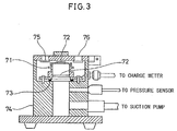
- Fig. 2 shows schematically this measuring system which comprises a main body measuring portion 7, a main body control portion 8, a charge meter 9, a balance 10 and a suction pump 11.
- Fig. 3 shows a cross-section of the main body measuring portion 7. A measuring procedure will be described. Firstly, a 400-mesh wire-netting 72 is attached to a faraday gauge 71 at an upper position and a lower position, respectively, and the mass of the empty faraday gauge 71 is measured. The mesh-netting 72 is replaced per ten measurements.
- toner particles Into this toner particles, 0.9 part by weight of magnetite as a finishing agent ("BL220W”, manufactured by Titan Kogyo K.K.), and a hydrophobic silica ("R812S”, manufactured by Nippon Aerosil Co., Ltd.) are added and mixed with high speed stirring by a Henschel's mixer to obtain toner particles, which is employed as a standard toner.
- BL220W magnetite as a finishing agent
- R812S hydrophobic silica
- the particles in order to incorporate particles having chargeability and/or conductivity with a predetermined particle size, into a coating resin, the particles may be added into a solution or dispersion liquid of the coating resin, which solution or dispersion may be then applied to the magnetic material particles.
- a coating resin is applied to the surface of magnetic material particles and then dried, the particles are allowed to adhere to and bury in the resin by mechanical impact force.
- particles having chargeability there may be, for example, metal oxides such as silica, chrome oxide, iron oxide, manganese oxides, molybdenum oxide, titanium oxide, tungsten oxide, vanadium oxide, aluminum oxide, magnesium oxide, silane oxide and zirconia oxide; dyes such as salicyl acid derivative and azo metal complex; and organic salt such as quaternary ammonium salt.
- metal oxides such as silica, chrome oxide, iron oxide, manganese oxides, molybdenum oxide, titanium oxide, tungsten oxide, vanadium oxide, aluminum oxide, magnesium oxide, silane oxide and zirconia oxide
- dyes such as salicyl acid derivative and azo metal complex
- organic salt such as quaternary ammonium salt.
- conductive particles there may be, for example, carbon black such as acetylene black and furnace black; carbide such as silane carbide, titanium carbide and zirconia carbide; and nitride such as boron nitride, neodymium nitride, titanium nitride and zirconia nitride.
- carbon black such as acetylene black and furnace black
- carbide such as silane carbide, titanium carbide and zirconia carbide
- nitride such as boron nitride, neodymium nitride, titanium nitride and zirconia nitride.
- a carrier for use in development of electrostatic latent image may be combined with toner particles in itself well known, for use in developing electrostatic latent image, as a two-component developer.
- Toner particles for two-component developer are obtained by dispersing a coloring agent, charge control agent and mold releasing agent into a binder resin, followed by granulating and, as desired, adding a flow improver.
- Preferable toner particles to be combined with a carrier for use in development of electrostatic latent image may be one which contains no charge control agent that is the main cause of spent toner (hereinafter referred to as "CCA less-toner” in some cases), from the point of view of increasing the carrier lifetime.
- CCA less-toner no charge control agent that is the main cause of spent toner
- a binder resin being one toner component
- a thermoplastic resin and a thermosetting resin which is not cured or of initial condensation product may be used.
- vinyl aromatic resin such as polystyrene, styrene-acrylic copolymer, acrylic resin, poly(vinyl acetal) resin, polyester resin, epoxy resin and phenol resin.
- a charge control agent is usually employed to control the charge quantity of toner.
- Preferable charge control agents having positively chargeability may be nigrosine base and quaternary ammonium salt.
- a preferable charge control agent having negative chargeability may be metal complex dye, salicylic acid derivative and sulfonic acid derivative.
- cationic polar group may be basic nitrogen containing group such as primary, secondary, tertiary or quaternary ammonia group, amide group, imino group, imide group, hydrazino group, guanidino group and amidino group.
- anionic polar group may be arbitrary polar groups such as carboxylic acid, sulfonic acid and phosphonic acid.
- resin may be ones which are obtained by copolymerization of a cationic or anionic polar group containing monomer, and other monomer or resin, by means of random copolymerization, block copolymerization, or grafting copolymerization.
- the following pigments are useable:
- the above pigment is preferably present in an amount of from 2 to 20 parts by weight, more preferably from 5 to 15 parts by weight, to 100 parts by weight of a binder resin.
- Olefin resin has a number average molecular weight (Mn) of from 1,000 to 10,000, particularly from 2,000 to 6,000.
- Mn number average molecular weight
- examples of the olefin resin are polypropylene, polyethylene and propylene-ethylene copolymer. Especially preferred is polypropylene.
- the magnetic powder may be added in small amounts, that is, from 0.1 to 5 parts by weight, especially from 0.5 to 3.0 parts by weight, to 100 parts by weight of a binder resin.
- Examples of the above magnetic powder are triiron tetroxide (Fe 3 O 4 ), diiron trioxide ( ⁇ -Fe 2 O 3 ), iron oxide zinc (ZnFe 3 O 4 ), iron oxide yttrium (Y 3 Fe 5 O 12 ), iron oxide cadmium (CdFe 2 O 4 ), iron oxide gadolinium (Gd 3 Fe 5 O 12 ), iron oxide copper (CuFe 2 O 4 ), iron oxide lead (PbFe 12 O 19 ), iron oxide nickel (NiFe 2 O 4 ), iron oxide neodymium (NdFeO 3 ), iron oxide barium (BaFe 12 O 19 ), iron oxide magnesium (MgFe 2 O 4 ), iron oxide manganese (MnFe 2 O 4 ), iron oxide lanthanum (LaFeO 3 ), iron powder (Fe), cobalt powder (Co), and nickel powder (Ni).
- Fe 3 O 4 triiron tetroxide
- ⁇ -Fe 2 O 3 iron oxide
- Particularly preferable magnetic powder may be fine particles of triiron tetroxide (magnetite).
- magnetite is of regular octahedron with a particle size of from 0.05 to 1 ⁇ m. This magnetite may be subjected to surface finishing with silane coupling agent, titan coupling agent, etc.
- Toner particles may be prepared by a method in itself well known, such as pulverization classification, melt granulation, spray granulation, copolymerization. Pulverization classification is usually employed. The respective toner particles as described are premixed by a mixer such as Henschel's mixer, and kneaded by a kneader such as a biaxial extruder. This is then cooled, pulverized and classified to obtain toner particles.
- a mixer such as Henschel's mixer
- a kneader such as a biaxial extruder
- Preferable toner particle size may be usually from 5 to 15 ⁇ m, particularly from 7 to 12 ⁇ m, which is based on median size with a Coulter counter.
- a flow improver such as hydrophobic vapor deposition silica may be added to the toner particle surface such as to adhere thereto, in order to improve toner fluidity.
- Flow improver is preferably added in an amount of from 0.1 to 2.0 wt% per toner.
- the efficiency of transfer may be improved by incorporating spacer particles whose particle size is greater than that of the flow improver, namely, from 0.05 to 1 ⁇ m, into the flow improver.
- any organic or inorganic inactive typical particles may be used.
- the above-mentioned magnetic powder is preferred, and the fine particles of triiron tetroxide (magnetite) is particularly preferable. This is because the magnetic powder residing on the toner particle surface is also effective in avoiding toner scattering.
- Spacer particles such as the fine particles of triiron tetroxide (magnetite) is preferably present in an amount of from 0.1 to 10 wt% per toner.
- Preferable material of a cleaning blade used in the embodiment may be elastomers such as urethane rubber and silicon rubber, and foam thereof. Particularly, silicon rubber causes less deterioration with time, thus maintaining good characteristic feature.
- leading system As a blade pressing system, either of leading system and trailing system may be employed.
- the abutting angle to an image bearing member depends upon the pressing system.
- the leading system in which the sum of pressing force and frictional force is exerted in the direction of compressing an elastic rubber blade, is preferable in cleaning coating resin pieces having a particle size smaller than toner particles, because it has high cleaning force and can perform effectively with a relatively small pressing force.
- a pressure release mechanism for releasing the blade pressure at the time of halt, and a pre-cleaning roller or brush for avoiding inferior cleaning due to the intervention of coating resin pieces.
- thrust mechanism and a scraper blade may be employed.
- the thrust mechanism moves a cleaning blade in a direction axially of an image bearing member.
- the scraper blade removes the substances such as coating resin pieces, adhered on the edge of a cleaning blade, per predetermined number of copied sheets.
- Pressing conditions of a cleaning blade may be suitably set depending upon the material and properties of an image bearing member, the characteristic feature of toner and coating resin, and the temperature in an image forming apparatus.
- preferable pressing conditions in leading system is as follows: the hardness of rubber is from 55 to 80° , the abutting angle between a blade and image bearing member is from 15 to 30° , and the pressure is from 5 to 15 g/cm.
- An image bearing member used in the embodiment may be understood to mean one having on its surface a photosensitive layer.
- Preferable photosensitive material to be incorporated into a photosensitive layer may be amorphous chalcogenide material including amorphous selenium and alloy thereof; II-VI group inorganic compound materials such as zinc oxide and cadmium sulfide; organic photoconductor material including high molecular series and resin dispersion complex series of low molecular weight organic compound; and amorphous silicon material.
- amorphous silicon there may be amorphous silicon germanium, amorphous silicon nitride, and material in which some hydrogen is substituted by fluorine.
- the image bearing member used in the embodiment may be in any form of sheet, belt, web or drum.
- Belt or drum form is preferable in view of high speed and compactness.
- Hardness was rank F .
- the coated carriers were then mixed with the above-mentioned standard toner.
- a cleaning blade (62° in blade hardness, 8.8 g/cm in pressure, and 18.63° in abutting angle), and an image forming apparatus shown in Fig. 1, as attachment conditions, carrier lifetime, image, physical properties and cleaning performance were determined by the following measuring methods and criteria. The results are summarized in Table 1.
- a developer comprised of coated carrier particles and standard toner particle was placed into a developing unit of the image forming apparatus.
- the developer was stirred continuously and the time at which the so-called "front draw” occurred in image was regarded as carrier lifetime.
- the density of a black solid portion of a copied image was measured on a reflection density meter (Model #TC-6D, Tokyo Denshoku Co., Ltd.). The obtained value was employed as image density.
- the density of a blank portion of a paper sheet which has no copy image was measured on the reflection density meter. The obtained value was employed as fogging density.
- the developer was collected from the developing sleeve surface and its weight was measured. After toner particles was separated from the developer by means of suction, its weight was measured and the percent by weight of the toner per developer was calculated.
- the developer was collected from the developing sleeve surface, and it was measured on a charge measuring system with isolation aspirator, manufactured by Sankyo Piotech Co., Ltd.
- mark “ ⁇ ” means the presence of image contamination
- mark “ ⁇ ” means the absence of image contamination (the cleaning blade lifetime corresponds to 200000 copied sheets)
- mark “o ⁇ ” means the absence of image contamination (the cleaning blade lifetime corresponds to 400000 copied sheets).
- Coated carrier particle were prepared in the same manner as in Example 1, except for the use of a thermoplastic copolymer resin comprised of methyl methacrylate with a weight-average molecular weight of from 25000 to 30000, and its derivative.
- the coating resin solution was dried and its hardness was measured by the above-mentioned measuring method. Hardness was rank B .
- After the coated carriers were mixed with the above-mentioned standard toner particles, carrier lifetime, image, physical properties and cleaning performance were determined by using the above-mentioned image forming apparatus. The results are summarized in Table 1.
- Coated carrier particles were prepared in the same manner as in Example 1, except that 0.5 part by weight of a thermoplastic copolymer resin comprised of methyl methacrylate (weight-average molecular weight: from 10000 to 20000) and its derivative, to 100 parts by weight of magnetic material particles, were dissolved in toluene to prepare a coating resin solution.
- the coating resin solution was dried and its hardness was measured by the above-mentioned measuring method. Hardness was rank F .
- Coated carrier particles were prepared in the same manner as in Example 1, except that 5 parts by weight of a thermoplastic copolymer resin comprised of methyl methacrylate (weight-average molecular weight: from 10000 to 20000) and its derivative, to 100 parts by weight of magnetic material particles, were dissolved in toluene to prepare a coating resin solution.
- a thermoplastic copolymer resin comprised of methyl methacrylate (weight-average molecular weight: from 10000 to 20000) and its derivative, to 100 parts by weight of magnetic material particles, were dissolved in toluene to prepare a coating resin solution.
- the coating resin solution was dried and its hardness was measured by the above-mentioned measuring method. Hardness was rank F .
- Coated carrier particles were prepared in the same manner as in Example 1, except that 0.1 part by weight of aluminum oxide (particle size: 0.02 ⁇ m) to 100 parts by weight of magnetic material particles was dispersed into a coating resin solution.
- the coating resin solution was dried and its hardness was measured by the above-mentioned measuring method. Hardness was rank F .
- Coated carrier particles were prepared in the same manner as in Example 1, except that 10 parts by weight of aluminum oxide (particle size: 0.02 ⁇ m) to 100 parts by weight of magnetic material particles was dispersed into a coating resin solution.
- the coating resin solution was dried and its hardness was measured on the above-mentioned measuring method. Hardness was rank F .
- Coated carrier particles were prepared in the same manner as in Example 1, except that 5 parts by weight of aluminum oxide (particle size: 0.005 ⁇ m) to 100 parts by weight of magnetic material particles was dispersed into a coating resin solution.
- the coating resin solution was dried and its hardness was measured by the above-mentioned measuring method. Hardness was rank F .
- Coated carrier particles were prepared in the same manner as in Example 1, except that 5 parts by weight of aluminum oxide (particle size: 1 ⁇ m) to 100 parts by weight of magnetic material particles was dispersed into a coating resin solution.
- the coating resin solution was dried and its hardness was measured by the above-mentioned measuring method. Hardness was rank F .
- Coated carrier particles were prepared in the same manner as in Example 1, except that 5 parts by weight of aluminum oxide (particle size: 0.02 ⁇ m) to 100 parts by weight of magnetic material particles was dispersed into a coating resin solution.
- the coating resin solution was dried and its hardness was measured by the above-mentioned measuring method. Hardness was rank F .
- Coated carrier particles were prepared in the same manner as in Example 1, except for the use of a magnetic material of manganese-zinc ferrite with an electrical resistance of 1.6 ⁇ 10 8 ⁇ ⁇ cm. The results are given in Table 1.
- Coated carrier particles were prepared in the same manner as in Example 1, except for the use of manganese-zinc ferrite with an electrical resistance of 1.2 ⁇ 10 10 ⁇ ⁇ cm. The results are given in Table 1.
- a coating machine (“Universal mixing-stirring machine", manufactured by Dalton Co., Ltd.) was placed 3 kg of magnetic material particles of a magnetic material of manganese-zinc ferrite with 70 ⁇ m in mean particle size and 60 Am 2 /kg in saturation magnetization. Separately, to 100 parts by weight of magnetic material particles, 0.5 part by weight of a thermosetting acrylic modified silicon resin was dissolved in toluene to obtain a coating resin solution. This solution was supplied to the coating machine and mixed with stirring together with magnetic material particles. At this time, the temperature was maintained at 150 °C, and the toluene was evaporated for curing the coating resin.
- Hardness was rank H .
- Coated carrier particles were prepared in the same manner as in Comparative Example 1, except that the curing temperature was changed from 150 °C to 180 °C. After the used coating resin solution was dried and cured at 180°C, its hardness was determined by the measuring method as described above. Hardness was rank 2H .
- Hardness was rank 2B .
- Coated carrier particles were prepared in the same manner as in Example 1, except that 0.4 part by weight of methyl methacrylate and a thermoplastic copolymer resin (weight-average molecular weight: from 10000 to 20000) as its derivative, to 100 parts by weight of magnetic material particles, were dissolved in toluene to prepare a coating resin solution.
- a thermoplastic copolymer resin weight-average molecular weight: from 10000 to 20000
- Hardness was rank F .
- Coated carrier particles were prepared in the same manner as in Example 1, except that 6 parts by weight of methyl methacrylate and a thermoplastic copolymer resin (weight-average molecular weight: from 10000 to 20000) as its derivative, to 100 parts by weight of magnetic material particles, were dissolved in toluene to prepare a coating resin solution. A number of aggregates of a size of several centimeters were recognized in the coated carriers.
- the carrier lifetime was in the range of from 90 to 120 hours, which corresponds to from 350000 to 470000 copied sheets, showing an extended lifetime. Further, in every Example, the spent quantity upon termination of useful lifetime was negative, showing that the coating resin on the carrier surface had peeled during useful lifetime. The peeling of the coating resin functions to minimize the difference between the initial charge quantity and the charge quantity upon termination of useful lifetime. In the image forming apparatus of Examples 1 to 14, since the coating resin pieces separated from the carrier surface was cleaned and removed by the cleaning blade, no image contamination was observed below 200000 copied sheets, showing good cleaning performance.
- each of the carriers of Comparative Examples 1 to 3, 5 and 6 had "front draw phenomenon" below 75 hours (which corresponds to 283000 copied sheets).
- the spent quantity was 0.030 wt% and 0.050 wt%, respectively, and the toner particles adhered to the carrier surface.
- the spent quantity was negative and the peeling of the coating resin was observed.
- the coating resin was soft, its peeling speed was too high and "front draw” occurred after the elapse of 74.1 hours and 73 hours, respectively.
- the carrier of Comparative Example 6 aggregated and it could not be used.
Landscapes
- Physics & Mathematics (AREA)
- General Physics & Mathematics (AREA)
- Developing Agents For Electrophotography (AREA)
Claims (7)
- Träger für die Verwendung in der Entwicklung eines elektrostatischen latenten Bildes, umfassend Teilchen aus einem magnetischen Material, die mit einem Beschichtungsharz beschichtet sind, wobei das Beschichtungsharz ein thermoplastisches Harz mit einer Härte der Stufe F bis B hinsichtlich eines Bleistiftkratztests ist und in einer Menge von 0,5 bis 5 Gewichtsteilen, bezogen auf 100 Gewichtsteile von Teilchen aus einem magnetischen Material, vorhanden ist.
- Träger nach Anspruch 1, wobei der Träger der folgenden Gleichung genügt:
- Träger nach Anspruch 1 oder 2, wobei Teilchen mit Aufladungsvermögen und/oder Leitfähigkeit und einer Teilchengröße von 0,005 bis 1 µm in einer Menge von 0,1 bis 10 Gewichtsteilen, bezogen auf 100 Gewichtsteile des Beschichtungsharzes, vorhanden sind.
- Bild-formende Vorrichtung, umfassend:wobei die Trägerkomponente Trägerteilchen einschließt, die jeweils Teilchen aus einem magnetischen Material aufweisen, die mit einem Beschichtungsharz beschichtet sind, wobei das Beschichtungsharz ein thermoplastisches Harz mit einer Härte der Stufe F bis B hinsichtlich eines Bleistiftkratztests ist und in einer Menge von 0,5 bis 5 Gewichtsteilen, bezogen auf 100 Gewichtsteile der Teilchen aus einem magnetischen Material, vorhanden ist.einen Entwicklungsabschnitt zum Entwickeln eines elektrostatischen latenten Bildes, gebildet auf einem Bild-tragenden Teil durch einen Entwickler, der eine Trägerkomponente und eine Tonerkomponente umfaßt,einen Übertragungsabschnitt zum Übertragen eines Tonerbildes auf dem Bild-tragenden Teil auf Kopierpapier undeinen Reinigungsabschnitt mit einer Reinigungsklinge zum Reinigen einer Oberfläche des Bild-tragenden Teils nach Übertragen,
- Bild-formende Vorrichtung nach Anspruch 4, wobei die Trägerteilchen der Gleichung genügen:
- Bild-formende Vorrichtung nach Anspruch 4 oder 5, wobei die Trägerteilchen Teilchen mit Aufladungsvermögen und/oder Leitfähigkeit und einer Teilchengröße von 0,005 bis 1 µm in einer Menge von 0,1 bis 10 Gewichtsteilen, bezogen auf 100 Gewichtsteile des Beschichtungsharzes, enthalten.
- Bild-formende Vorrichtung nach einem der Ansprüche 4 bis 6, wobei das Bild-tragende Teil einen Photorezeptor mit einer photosensiblen Schicht, die amorphes Silicium umfaßt, einschließt.
Applications Claiming Priority (4)
| Application Number | Priority Date | Filing Date | Title |
|---|---|---|---|
| JP21128398 | 1998-07-27 | ||
| JP21128498 | 1998-07-27 | ||
| JP21128498 | 1998-07-27 | ||
| JP21128398 | 1998-07-27 |
Publications (2)
| Publication Number | Publication Date |
|---|---|
| EP0977094A1 EP0977094A1 (de) | 2000-02-02 |
| EP0977094B1 true EP0977094B1 (de) | 2003-09-24 |
Family
ID=26518539
Family Applications (1)
| Application Number | Title | Priority Date | Filing Date |
|---|---|---|---|
| EP99114620A Expired - Lifetime EP0977094B1 (de) | 1998-07-27 | 1999-07-26 | Träger für die Entwicklung elektrostatischer latenter Bilder und diesen Träger benutzendes Bildherstellungsgerät |
Country Status (3)
| Country | Link |
|---|---|
| US (1) | US6130018A (de) |
| EP (1) | EP0977094B1 (de) |
| DE (1) | DE69911520T2 (de) |
Families Citing this family (9)
| Publication number | Priority date | Publication date | Assignee | Title |
|---|---|---|---|---|
| US6480695B2 (en) * | 2000-05-10 | 2002-11-12 | Konica Corporation | Cleaning system and image forming method |
| US7088946B2 (en) * | 2004-04-12 | 2006-08-08 | Eastman Kodak Company | Adjusting gloss for a print image |
| JP4544095B2 (ja) * | 2005-08-24 | 2010-09-15 | 富士ゼロックス株式会社 | 電子写真用トナー、電子写真用トナーの製造方法、電子写真用現像剤並びに画像形成方法 |
| JP2010181438A (ja) * | 2009-02-03 | 2010-08-19 | Fuji Xerox Co Ltd | 静電荷像現像トナー用ポリエステル樹脂及びその製造方法、静電荷像現像トナー、静電荷像現像剤、トナーカートリッジ、プロセスカートリッジ、画像形成方法、並びに、画像形成装置 |
| KR20140120990A (ko) | 2013-04-03 | 2014-10-15 | 삼성전자주식회사 | 전자사진 감광체 및 이를 채용한 화상 형성 장치 |
| US9581924B2 (en) * | 2014-11-14 | 2017-02-28 | Xerox Corporation | Bio-based acrylate and (meth)acrylate resins |
| JP7404799B2 (ja) * | 2019-11-15 | 2023-12-26 | 株式会社リコー | 電子写真画像形成用キャリア、電子写真画像形成用現像剤、電子写真画像形成方法、電子写真画像形成装置およびプロセスカートリッジ |
| JP7673451B2 (ja) * | 2021-03-23 | 2025-05-09 | 富士フイルムビジネスイノベーション株式会社 | 静電荷像現像用キャリア、静電荷像現像剤、プロセスカートリッジ、画像形成装置及び画像形成方法 |
| JP2022147732A (ja) * | 2021-03-23 | 2022-10-06 | 富士フイルムビジネスイノベーション株式会社 | 静電荷像現像用キャリア、静電荷像現像剤、プロセスカートリッジ、画像形成装置及び画像形成方法 |
Family Cites Families (8)
| Publication number | Priority date | Publication date | Assignee | Title |
|---|---|---|---|---|
| US3811880A (en) * | 1970-05-08 | 1974-05-21 | Addressograph Multigraph | Method and materials for control of contact electrostatic development |
| US3767578A (en) * | 1971-06-10 | 1973-10-23 | Xerox Corp | Carrier material for electrostatographic developer |
| JPH0820774B2 (ja) * | 1986-06-17 | 1996-03-04 | 富士ゼロックス株式会社 | 現像剤用キヤリヤ |
| JP3077708B2 (ja) * | 1991-04-16 | 2000-08-14 | 富士ゼロックス株式会社 | 静電荷像現像用キャリア |
| JP2840158B2 (ja) * | 1992-04-24 | 1998-12-24 | 富士通株式会社 | 二成分現像剤 |
| US5332637A (en) * | 1993-08-31 | 1994-07-26 | Eastman Kodak Company | Electrostatographic dry toner and developer compositions with hydroxyphthalimide |
| JPH07181748A (ja) * | 1993-12-21 | 1995-07-21 | Ricoh Co Ltd | 静電潜像現像用二成分系現像剤 |
| JP3794506B2 (ja) * | 1995-05-15 | 2006-07-05 | コニカミノルタホールディングス株式会社 | 静電荷潜像現像用キャリア及び静電荷潜像現像用現像剤 |
-
1999
- 1999-07-26 EP EP99114620A patent/EP0977094B1/de not_active Expired - Lifetime
- 1999-07-26 DE DE69911520T patent/DE69911520T2/de not_active Expired - Fee Related
- 1999-07-27 US US09/361,412 patent/US6130018A/en not_active Expired - Fee Related
Also Published As
| Publication number | Publication date |
|---|---|
| US6130018A (en) | 2000-10-10 |
| DE69911520T2 (de) | 2004-08-05 |
| DE69911520D1 (de) | 2003-10-30 |
| EP0977094A1 (de) | 2000-02-02 |
Similar Documents
| Publication | Publication Date | Title |
|---|---|---|
| US6183925B1 (en) | Two component developer comprising specific magnetic toner and specific magnetic carrier | |
| EP0977094B1 (de) | Träger für die Entwicklung elektrostatischer latenter Bilder und diesen Träger benutzendes Bildherstellungsgerät | |
| JP3429219B2 (ja) | 静電潜像現像用キャリアおよびそれを用いた画像形成装置 | |
| JPH09281751A (ja) | 静電潜像現像用キャリア | |
| JP2836149B2 (ja) | 二成分現像剤 | |
| JPH0876485A (ja) | 二成分系現像剤 | |
| JPH0876511A (ja) | 二成分系現像剤 | |
| JPH02219063A (ja) | 電子写真用乾式二成分現像剤 | |
| JPH0876444A (ja) | 二成分系現像剤 | |
| JPH0876495A (ja) | 二成分系現像剤 | |
| JPH0876482A (ja) | 二成分系現像剤 | |
| JPH0876437A (ja) | 二成分系現像剤 | |
| JPH0876474A (ja) | 二成分系現像剤 | |
| JPH0876509A (ja) | 二成分系現像剤 | |
| JPH0876498A (ja) | 二成分系現像剤 | |
| JPH03255462A (ja) | 電子写真用二成分現像剤及びその製造方法 | |
| JPH0876488A (ja) | 二成分系現像剤 | |
| JPH0876493A (ja) | 二成分系現像剤 | |
| JPH0876487A (ja) | 二成分系現像剤 | |
| JPH0876486A (ja) | 二成分系現像剤 | |
| JPH0876471A (ja) | 二成分系現像剤 | |
| JPH0876453A (ja) | 二成分系現像剤 | |
| JPH0876450A (ja) | 二成分系現像剤 | |
| JPH09152747A (ja) | 二成分現像剤用キャリア | |
| JPH0876491A (ja) | 二成分系現像剤 |
Legal Events
| Date | Code | Title | Description |
|---|---|---|---|
| PUAI | Public reference made under article 153(3) epc to a published international application that has entered the european phase |
Free format text: ORIGINAL CODE: 0009012 |
|
| AK | Designated contracting states |
Kind code of ref document: A1 Designated state(s): CH DE GB LI |
|
| AX | Request for extension of the european patent |
Free format text: AL;LT;LV;MK;RO;SI |
|
| 17P | Request for examination filed |
Effective date: 20000316 |
|
| RAP1 | Party data changed (applicant data changed or rights of an application transferred) |
Owner name: KYOCERA MITA CORPORATION |
|
| AKX | Designation fees paid |
Free format text: CH DE GB LI |
|
| GRAH | Despatch of communication of intention to grant a patent |
Free format text: ORIGINAL CODE: EPIDOS IGRA |
|
| GRAH | Despatch of communication of intention to grant a patent |
Free format text: ORIGINAL CODE: EPIDOS IGRA |
|
| GRAA | (expected) grant |
Free format text: ORIGINAL CODE: 0009210 |
|
| AK | Designated contracting states |
Kind code of ref document: B1 Designated state(s): CH DE GB LI |
|
| REG | Reference to a national code |
Ref country code: GB Ref legal event code: FG4D |
|
| REG | Reference to a national code |
Ref country code: CH Ref legal event code: EP |
|
| REG | Reference to a national code |
Ref country code: CH Ref legal event code: NV Representative=s name: A. BRAUN, BRAUN, HERITIER, ESCHMANN AG PATENTANWAE |
|
| REF | Corresponds to: |
Ref document number: 69911520 Country of ref document: DE Date of ref document: 20031030 Kind code of ref document: P |
|
| PLBE | No opposition filed within time limit |
Free format text: ORIGINAL CODE: 0009261 |
|
| STAA | Information on the status of an ep patent application or granted ep patent |
Free format text: STATUS: NO OPPOSITION FILED WITHIN TIME LIMIT |
|
| 26N | No opposition filed |
Effective date: 20040625 |
|
| PGFP | Annual fee paid to national office [announced via postgrant information from national office to epo] |
Ref country code: GB Payment date: 20050720 Year of fee payment: 7 |
|
| PGFP | Annual fee paid to national office [announced via postgrant information from national office to epo] |
Ref country code: DE Payment date: 20050721 Year of fee payment: 7 |
|
| PGFP | Annual fee paid to national office [announced via postgrant information from national office to epo] |
Ref country code: CH Payment date: 20050727 Year of fee payment: 7 |
|
| PG25 | Lapsed in a contracting state [announced via postgrant information from national office to epo] |
Ref country code: GB Free format text: LAPSE BECAUSE OF NON-PAYMENT OF DUE FEES Effective date: 20060726 |
|
| PG25 | Lapsed in a contracting state [announced via postgrant information from national office to epo] |
Ref country code: LI Free format text: LAPSE BECAUSE OF NON-PAYMENT OF DUE FEES Effective date: 20060731 Ref country code: CH Free format text: LAPSE BECAUSE OF NON-PAYMENT OF DUE FEES Effective date: 20060731 |
|
| PG25 | Lapsed in a contracting state [announced via postgrant information from national office to epo] |
Ref country code: DE Free format text: LAPSE BECAUSE OF NON-PAYMENT OF DUE FEES Effective date: 20070201 |
|
| REG | Reference to a national code |
Ref country code: CH Ref legal event code: PL |
|
| GBPC | Gb: european patent ceased through non-payment of renewal fee |
Effective date: 20060726 |