EP0976919B1 - Turbocompresseur avec soupape de décharge - Google Patents
Turbocompresseur avec soupape de décharge Download PDFInfo
- Publication number
- EP0976919B1 EP0976919B1 EP99303810A EP99303810A EP0976919B1 EP 0976919 B1 EP0976919 B1 EP 0976919B1 EP 99303810 A EP99303810 A EP 99303810A EP 99303810 A EP99303810 A EP 99303810A EP 0976919 B1 EP0976919 B1 EP 0976919B1
- Authority
- EP
- European Patent Office
- Prior art keywords
- actuator
- rod
- turbocharger
- lever arm
- actuator rod
- Prior art date
- Legal status (The legal status is an assumption and is not a legal conclusion. Google has not performed a legal analysis and makes no representation as to the accuracy of the status listed.)
- Expired - Lifetime
Links
Images


Classifications
-
- F—MECHANICAL ENGINEERING; LIGHTING; HEATING; WEAPONS; BLASTING
- F02—COMBUSTION ENGINES; HOT-GAS OR COMBUSTION-PRODUCT ENGINE PLANTS
- F02B—INTERNAL-COMBUSTION PISTON ENGINES; COMBUSTION ENGINES IN GENERAL
- F02B37/00—Engines characterised by provision of pumps driven at least for part of the time by exhaust
- F02B37/12—Control of the pumps
- F02B37/18—Control of the pumps by bypassing exhaust from the inlet to the outlet of turbine or to the atmosphere
- F02B37/183—Arrangements of bypass valves or actuators therefor
- F02B37/186—Arrangements of actuators or linkage for bypass valves
-
- F—MECHANICAL ENGINEERING; LIGHTING; HEATING; WEAPONS; BLASTING
- F01—MACHINES OR ENGINES IN GENERAL; ENGINE PLANTS IN GENERAL; STEAM ENGINES
- F01D—NON-POSITIVE DISPLACEMENT MACHINES OR ENGINES, e.g. STEAM TURBINES
- F01D17/00—Regulating or controlling by varying flow
- F01D17/10—Final actuators
- F01D17/105—Final actuators by passing part of the fluid
-
- F—MECHANICAL ENGINEERING; LIGHTING; HEATING; WEAPONS; BLASTING
- F05—INDEXING SCHEMES RELATING TO ENGINES OR PUMPS IN VARIOUS SUBCLASSES OF CLASSES F01-F04
- F05D—INDEXING SCHEME FOR ASPECTS RELATING TO NON-POSITIVE-DISPLACEMENT MACHINES OR ENGINES, GAS-TURBINES OR JET-PROPULSION PLANTS
- F05D2220/00—Application
- F05D2220/40—Application in turbochargers
-
- F—MECHANICAL ENGINEERING; LIGHTING; HEATING; WEAPONS; BLASTING
- F05—INDEXING SCHEMES RELATING TO ENGINES OR PUMPS IN VARIOUS SUBCLASSES OF CLASSES F01-F04
- F05D—INDEXING SCHEME FOR ASPECTS RELATING TO NON-POSITIVE-DISPLACEMENT MACHINES OR ENGINES, GAS-TURBINES OR JET-PROPULSION PLANTS
- F05D2260/00—Function
- F05D2260/50—Kinematic linkage, i.e. transmission of position
- F05D2260/57—Kinematic linkage, i.e. transmission of position using servos, independent actuators, etc.
-
- Y—GENERAL TAGGING OF NEW TECHNOLOGICAL DEVELOPMENTS; GENERAL TAGGING OF CROSS-SECTIONAL TECHNOLOGIES SPANNING OVER SEVERAL SECTIONS OF THE IPC; TECHNICAL SUBJECTS COVERED BY FORMER USPC CROSS-REFERENCE ART COLLECTIONS [XRACs] AND DIGESTS
- Y02—TECHNOLOGIES OR APPLICATIONS FOR MITIGATION OR ADAPTATION AGAINST CLIMATE CHANGE
- Y02T—CLIMATE CHANGE MITIGATION TECHNOLOGIES RELATED TO TRANSPORTATION
- Y02T10/00—Road transport of goods or passengers
- Y02T10/10—Internal combustion engine [ICE] based vehicles
- Y02T10/12—Improving ICE efficiencies
Definitions
- This invention relates to a turbocharger incorporating a wastegate and wastegate actuator, and in particular relates to the manner in which the actuator is connected to the wastegate.
- Turbochargers are well known devices for supplying air to the intake of an internal combustion engine at pressures above atmospheric (boost pressures), and are widely used in automobiles and the like.
- a conventional turbocharger essentially comprises an exhaust gas driven turbine wheel mounted on a rotatable shaft within a turbine housing.
- the turbine housing defines an annular inlet passageway around the turbine wheel and a generally cylindrical axial outlet passageway extending from the turbine wheel.
- Rotation of the turbine wheel rotates a compressor wheel mounted on the other end of the shaft within a compressor housing.
- the compressor wheel delivers compressed air to the intake manifold of the engine, thereby increasing engine power.
- turbochargers with a bypass passageway between the exhaust inlet and the exhaust outlet portions of the turbine housing to enable control of the turbocharger boost pressure.
- a wastegate valve is located in the passageway and is controlled to open the passageway when the pressure level of the boost air increases to a predetermined level, thus allowing some of the exhaust gas to bypass the turbine wheel preventing the boost pressure from rising further.
- the wastegate valve is generally actuated by a pneumatic actuator operated by boost air pressure delivered by the compressor wheel.
- the conventional pneumatic actuator comprises a spring loaded diaphragm housed within a canister (the wastegate actuator can) which is mounted to the compressor housing.
- the diaphragm acts on a connecting rod which actuates the wastegate valve assembly which is mounted in the turbine housing.
- the actuator can is connected to the compressor outlet by a flexible hose to deliver boost air to the can which acts on the diaphragm to oppose the spring bias.
- the spring is selected, and the actuator and wastegate valve initially set, so that under low boost conditions the wastegate valve remains closed. However, when the boost pressure reaches a predetermined maximum the diaphragm is moved against the action of the spring and operates to open the wastegate valve (via the connecting rod and linking arm) thereby allowing some exhaust gas to bypass the turbine wheel.
- the wastegate valve is mounted on a valve stem which extends through the turbine housing and which is rotated to open and close the valve. Rotation of the valve stem is achieved by the reciprocal motion of the actuator rod (as the spring loaded diaphragm moves back and forth within the actuator canister) via a lever arm which links the end of the actuator rod to the valve stem.
- a pivotable joint between the lever arm and the actuator rod the opposite end of the lever arm being secured (typically by welding) to the end of the valve stem.
- the diaphragm maintains alignment within the canister, and thus that the rod maintains its alignment along the axis of the canister. It is therefore known to design the pivotal joint between the actuator rod and the lever arm to allow a slight amount of movement along axis of the lever arm to limit the tendency of the actuator rod to be pulled off-line as it reciprocates.
- the pressure at which the wastegate valve begins to open is critical and must therefore must be very carefully set when the actuator and wastegate are assembled to the turbocharger.
- initial set up is achieved by a process known as “weld to set”.
- the actuator canister, actuating rod, and the lever arm are pre-assembled, and mounted to the turbocharger.
- the wastegate valve is then clamped shut from within the turbine housing and the actuator canister is pressurised to the desired lift off pressure.
- the end of the lever arm is welded to the valve stem. Accordingly, any increase in the pressure supply to the actuator above the predetermined lift off pressure will cause the valve to open.
- the steps involved in the weld to set process can therefore be summarised as: holding the valve member in a closed position; pressurising the actuator canister to the lift off pressure; adjusting the length of the actuator rod; and then welding the end of the lever arm to the valve stem.
- an actuator rod for a turbocharger pressure control assembly comprising a first elongate portion defining a first rod end, and a second portion defining a second rod end, said first and second portions being pivotally joined to one another to allow a degree of relative pivotal motion between said two portions in at least one plane perpendicular to the axis of said elongate first portion, characterised in that the pivotal joint between said first and second portions preferably allows pivotal motion in at least two orthogonal planes perpendicular to the axis of said first elongate portion.
- the pivotal joint is preferably a spherical joint.
- a pressure control actuator assembly for a turbocharger comprising a pneumatic actuator and an actuating rod according to any preceding claim.
- a turbocharger including a pressure control assembly comprising a pneumatic actuator, a valve assembly, and an actuating rod according to any preceding claim one end of which is connected to the actuator and the other end of which is connected to the valve assembly, whereby the pneumatic actuator controls operation of the valve assembly via the actuator rod.
- a pressure control assembly of a turbocharger comprising a turbine housing and a compressor
- the pressure control assembly comprising a valve assembly mounted within the turbine housing, a pneumatic actuator mounted to the turbocharger to receive pressurised air from the compressor, an actuator rod extending from the pneumatic actuator, and a lever arm extending from the valve assembly and the turbine housing and linking the actuator rod to the valve assembly, wherein the actuator rod is a rod according to any one of claims 1 to 4, the method comprising:
- the actuator rod is preferably secured to the lever arm by welding or otherwise bonding.
- valve assembly is held in a closed position by appropriate clamping of the lever arm and said pneumatic actuator is pressurised to a predetermined pressure, thereby to determine the minimum pressure at which said valve will in use begin to open.
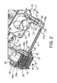
- the illustrated turbocharger is of a centripetal type, comprising a turbine indicated generally by the reference numeral 1 and a compressor illustrated generally by the reference numeral 2.
- the turbine 1 comprises a turbine housing 3 which houses a turbine wheel 4.
- the compressor 2 comprises a compressor housing 5 which houses a compressor wheel 6.
- the turbine wheel 4 and compressor wheel 6 are mounted on opposite ends of a common shaft 7.
- the turbine housing 3 and compressor housing 5 are joined together by a conventional circular V-band clamp 8.
- the turbine housing 3 is provided with an exhaust gas inlet 9 and an exhaust gas outlet 10.
- the inlet 9 directs incoming exhaust gas to an annular inlet chamber which surrounds the turbine wheel 4.
- the exhaust gas flows through the turbine and into the outlet 10 via a circular outlet opening which is coaxial with the turbine wheel 4 and directs exhaust gas to an outlet pipe 20.
- the turbine housing 3 also defines a bypass passageway 11 which communicates between the exhaust inlet 9 and the exhaust outlet 10 bypassing the turbine wheel 4.
- the bypass passageway 11 communicates with the exhaust inlet 9 via a circular opening which is closed by the valve member 12a of a wastegate valve 12 provided for controlling the flow therethrough.
- the actuator 13 comprises a diaphragm 15 mounted within a canister (the actuator can) 16 on one end of an actuating rod 17.
- the rod 17 extends from the front of the canister 16 towards the turbine housing 3 and the wastegate valve 12.
- the diaphragm 15 is biased towards the rear of the actuator can 16 by a coil spring 18 mounted coaxially around the actuator rod 17 and acting between the diaphragm 15 and the front end of the actuator can 16.
- the actuator can 16 is closed at its rear end by a cap 16a (which is crimped to the main body of the can).
- the can 16 is cut-away to reveal details of the spring 18 and diaphragm 15; it will be appreciated however that the can 16 is actually a closed unit.
- the compressor housing 5 is provided with a mounting bracket 25 for mounting the actuator 13, and a passageway 26 which communicates with the compressor outlet volute 14 and the end of the pipe 23.
- the passageway 26 is provided with an enlarged diameter annular opening 26a to receive an O-ring 24 which seats on a flange 23a of the connecting pipe 23.
- the mounting bracket 25 comprises two forked arms 25a and 25b which define slots 27 to receive actuator mounting bolts 28 the shafts of which extend from the actuator can 16, the can 16 being fixed in position by nuts 30 threaded onto the bolts 28.
- the actuator rod 17 is linked to the valve 12 via a lever arm 19 which is attached to the end of a valve stem 20 which passes through a bush 21 provided within the turbine housing 3.
- the actuator rod 17 is provided with a spherical rod end joint 17a, 17b at its end (shown partly cut-away in figures 1 and 2 to reveal detail) which is connected to the lever arm 19. In the position shown in Figures 1 and 2, with the diaphragm biased towards the back of the actuating can 16, it will be seen that the valve member 12a is in a closed position.
- the wastegate valve 12 In use, the wastegate valve 12 will in low boost conditions be held closed by the action of the spring 18 on the diaphragm 15 which is connected to the actuator rod 17. However, once the pressure in the compressor outlet volute 14 reaches a predetermined limit, the pressurised air transmitted to the actuator 13 via the connecting pipe 23 will push the diaphragm 15 against the action of the spring 18 thereby opening the wastegate valve to allow inlet exhaust gas to bypass the turbine. In this way, the maximum boost pressure produced by the turbocharger can be controlled and limited.
- the spherical rod end joint comprises a spherical actuator rod end 17a and a cylindrical rod end piece 17b which provides a socket for the spherical rod end 17a and which is welded to the lever arm.
- the spherical rod end joint 17a/17b provides for relative movement between the actuator rod 17 and the lever arm so that the actuator rod 17 maintains its alignment with the actuator can as it reciprocates back and forth.
- the spherical rod end joint also obviates the need to provide an adjustable length actuator rod 17, and enables a simplified set up procedure, as described below.
- the lever arm 19 in accordance with the present invention is pre-assembled together with the wastegate valve rather than as part of the actuator assembly. The lever arm 19 is attached to the valve stem 20 before the actuator is mounted to the turbocharger.
- the valve is clamped shut and the pressure in the actuator increased to the desired lift off pressure.
- the valve can be held shut by appropriate clamping of the lever arm 19 which is already connected to the valve stem.
- the end piece 17b of the actuator rod 17 With the valve thus clamped in the closed position, the end piece 17b of the actuator rod 17 is located within a part cylindrical portion 19a of the lever arm 19 and the two are welded together at two points. It will be appreciated that there is therefore no need to provide an adjustable length actuator rod 17 since the effective length of the actuator rod is automatically determined at set up before the rod is welded to the lever arm 19 simply by positioning the rod end piece 17b on the lever arm 19. Variations in spring rates will simply mean that the exact position of the lever arm 19 along the axis of the actuator rod 17 may vary from one turbocharger to the next.
- lever arm 19 on the valve stem 20 will have to be in a predetermined location to ensure that it extends in the correct orientation to receive the end of the actuator rod 17, but a certain amount of tolerance will be allowed for by the pivotal freedom of the spherical rod end joint.
- the spherical rod end joint will allow for any slight misalignment of the actuator rod 17 as a result of any variation in the exact positioning of the actuator can on the bracket 25.
- the degree of freedom of movement provided by the spherical rod end joint does not have any adverse affect of the operation of the actuator, since with the valve closed the rod 17 is in tension.
- the setting operation in accordance with the present invention has advantages over the prior art weld to set methods, particularly in that the valve can be held in a closed position by a clamp applied to a lever arm external of the turbine housing, and that there is no need to adjust the length of the actuator rod prior to making the weld.
Landscapes
- Engineering & Computer Science (AREA)
- Mechanical Engineering (AREA)
- General Engineering & Computer Science (AREA)
- Chemical & Material Sciences (AREA)
- Combustion & Propulsion (AREA)
- Supercharger (AREA)
Claims (11)
- Tige d'actionnement pour un ensemble de commande de pression d'un turbocompresseur, la tige d'actionnement (17, 17a, 17b) comprenant une première partie allongée (17) définissant une première extrémité de tige, et une seconde partie (17b) définissant une seconde extrémité de tige, lesdites première et seconde parties étant jointes l'une à l'autre de manière pivotante pour permettre un degré de mouvement pivotant relatif entre lesdites deux parties dans au moins un plan contenant l'axe de ladite première partie allongée (17), caractérisée en ce que le joint pivotant (17a, 17b) entre lesdites première et seconde parties (17a, 17b) permet le mouvement pivotant dans au moins deux plans orthogonaux contenant l'axe de ladite première partie allongée
- Tige d'actionnement selon la revendication 1, dans laquelle le joint pivotant est un joint sphérique (17a, 17b).
- Tige d'actionnement selon la revendication 2, dans lequel ledit joint sphérique (17a, 17b) comprend une formation sphérique définie par une desdites première et seconde parties (17), et un support défini par l'autre desdites première et seconde parties (17b) pour recevoir ladite formation sphérique.
- Ensemble d'actionnement de commande de pression pour un turbocompresseur, comprenant un actionneur pneumatique (13) et une tige d'actionnement (17, 17a, 17b) selon une quelconque revendication précédente.
- Ensemble d'actionnement selon la revendication 4, dans lequel l'actionneur pneumatique (13) comprend un diaphragme chargé par ressort (15) logé à l'intérieur d'une chambre sous pression (16), ledit diaphragme (15) étant attaché à ladite première extrémité de la tige d'actionnement (17).
- Turbocompresseur incluant un ensemble de commande de pression comprenant un actionneur pneumatique (13), un ensemble à soupape (12), et une tige d'actionnement (17, 17a, 17b) selon une quelconque revendication précédente dont une extrémité est connectée à l'actionneur (13) et dont l'autre extrémité est connectée à l'ensemble à soupape (12), de sorte que l'actionneur pneumatique (13) commande le fonctionnement de l'ensemble à soupape (12) via la tige d'actionnement (17, 17a, 17b).
- Turbocompresseur selon la revendication 6, dans lequel l'actionneur comprend (13) un diaphragme chargé par ressort (15) fixé à l'extrémité de la tige d'actionnement définie par ladite première partie allongée (17), et ladite seconde partie (17b) de la tige d'actionnement est fixée à un bras de levier (19) s'étendant à partir de l'ensemble à soupape (12) au moyen duquel la soupape est actionnée.
- Turbocompresseur selon la revendication 7, dans lequel ladite seconde partie (17b) de la tige d'actionnement est soudée audit bras de levier (19).
- Procédé d'assemblage d'un ensemble de commande de pression d'un turbocompresseur, le turbocompresseur comprenant un logement de turbine (3) et un compresseur (2), l'ensemble de commande de pression comprenant un ensemble à soupape (12) monté à l'intérieur du logement de turbine (3), un actionneur pneumatique (13) agencé sur le turbocompresseur pour recevoir de l'air pressurisé à partir du compresseur (2), une tige d'actionnement (17, 17a, 17b) s'étendant à partir de l'actionneur pneumatique (13), et un bras de levier (19) s'étendant à partir de l'ensemble à soupape (12) et du logement de turbine (3) et reliant la tige d'actionnement (17, 17a, 17b) à l'ensemble à soupape (12), dans lequel la tige d'actionnement (17, 17a, 17b) est une tige selon une quelconque des revendications 1 à 4, le procédé comprenant:l'assemblage de l'ensemble à soupape (12) et du bras de levier (19) sur le logement de turbine (5);l'assemblage de l'actionneur pneumatique (13) et de la tige d'actionnement (17, 17a, 17b) en un sous-ensemble;le montage du sous-ensemble actionneur pneumatique/tige d'actionnement (13, 17, 17a,17b) sur le turbocompresseur; etla fixation de la seconde partie (17b) de la tige d'actionnement au bras de levier (19).
- Procédé selon la revendication 9, dans lequel la tige d'actionnement (17, 17a, 17b) est fixée au bras de levier (19) par une soudure ou par une autre forme de liaison.
- Procédé selon la revendication 9 ou la revendication 10, dans lequel avant la fixation de la tige d'actionnement (17, 17a, 17b) au bras de levier (19), l'ensemble à soupape (12) est maintenu dans une position fermée par un serrage approprié du bras de levier (19) et ledit actionneur pneumatique (13) est pressurisé à une pression prédéterminée, de manière à déterminer la pression minimale à laquelle ladite soupape (12) commencera à s'ouvrir en service.
Applications Claiming Priority (2)
| Application Number | Priority Date | Filing Date | Title |
|---|---|---|---|
| GBGB9816275.3A GB9816275D0 (en) | 1998-07-27 | 1998-07-27 | Turbocharger with wastegate |
| GB9816275 | 1998-07-27 |
Publications (3)
| Publication Number | Publication Date |
|---|---|
| EP0976919A2 EP0976919A2 (fr) | 2000-02-02 |
| EP0976919A3 EP0976919A3 (fr) | 2001-05-02 |
| EP0976919B1 true EP0976919B1 (fr) | 2004-12-01 |
Family
ID=10836202
Family Applications (1)
| Application Number | Title | Priority Date | Filing Date |
|---|---|---|---|
| EP99303810A Expired - Lifetime EP0976919B1 (fr) | 1998-07-27 | 1999-05-17 | Turbocompresseur avec soupape de décharge |
Country Status (6)
| Country | Link |
|---|---|
| US (2) | US6658846B1 (fr) |
| EP (1) | EP0976919B1 (fr) |
| JP (1) | JP2000054851A (fr) |
| CN (1) | CN1204334C (fr) |
| DE (1) | DE69922302T2 (fr) |
| GB (1) | GB9816275D0 (fr) |
Cited By (5)
| Publication number | Priority date | Publication date | Assignee | Title |
|---|---|---|---|---|
| DE102010004559A1 (de) | 2010-01-14 | 2011-07-21 | Bosch Mahle Turbo Systems GmbH & Co. KG, 70376 | Verbindungseinrichtung, Antriebseinrichtung und Ladeeinrichtung |
| DE102012211443A1 (de) | 2012-07-02 | 2014-01-02 | Mahle International Gmbh | Stellvorrichtung und Zahnradanordnung |
| DE102012211444A1 (de) | 2012-07-02 | 2014-01-02 | Mahle International Gmbh | Stelleinrichtung, Kugelgelenk und Herstellungsverfahren |
| DE102012211535A1 (de) | 2012-07-03 | 2014-01-09 | Mahle International Gmbh | Stellvorrichtung und Gelenk |
| WO2015003921A1 (fr) * | 2013-07-11 | 2015-01-15 | Continental Automotive Gmbh | Dispositif de commande du clapet de décharge d'un turbocompresseur à gaz d'échappement |
Families Citing this family (36)
| Publication number | Priority date | Publication date | Assignee | Title |
|---|---|---|---|---|
| GB0111681D0 (en) | 2001-05-11 | 2001-07-04 | Holset Engineering Co | Turbo charger with waste gate |
| US20060130479A1 (en) * | 2004-12-21 | 2006-06-22 | Holm Christopher E | Turbocharger with blow-by gas injection port |
| US7290392B2 (en) * | 2005-09-06 | 2007-11-06 | Tia1 Products, Inc. | Wastegate actuator mounting bracket, turbocharger incorporating the bracket, and method of using same |
| DE102006028015A1 (de) | 2006-06-19 | 2007-12-20 | Robert Bosch Gmbh | Pneumatischer Stellantrieb mit integrierter elektropneumatischer Positionsregelung |
| US8499432B2 (en) * | 2007-03-06 | 2013-08-06 | Borgwarner Inc. | Wastegate assembly |
| US8206133B2 (en) * | 2008-08-12 | 2012-06-26 | GM Global Technology Operations LLC | Turbocharger housing with integral inlet and outlet openings |
| DE102008042535A1 (de) | 2008-10-01 | 2010-04-08 | Robert Bosch Gmbh | Elektropneumatischer Stellungsregler |
| KR101768918B1 (ko) * | 2009-03-09 | 2017-08-17 | 보르그워너 인코퍼레이티드 | 배기 가스 터보차저 |
| DE102009054241A1 (de) | 2009-11-21 | 2011-05-26 | Volkswagen Ag | Verfahren zur Montage und Einstellung eines Stellglieds eines Abgasturboladers sowie ein elektrisches Stellmittel |
| EP2473724B1 (fr) | 2009-09-03 | 2014-04-23 | Volkswagen Aktiengesellschaft | Dispositif by-pass pour turbo compresseur |
| IT1396413B1 (it) * | 2009-10-30 | 2012-11-19 | Natali | Metodo per la taratura di attuatori pneumatici ed attuatore tarato cosi' ottenibile. |
| DE102009057161A1 (de) | 2009-12-05 | 2011-06-09 | Volkswagen Ag | Abgasturbolader mit einem Bypassventil und ein hierfür bestimmtes Stellglied |
| DE102010018740A1 (de) | 2010-04-29 | 2011-11-03 | Bosch Mahle Turbo Systems Gmbh & Co. Kg | Ladeeinrichtung |
| WO2012034843A1 (fr) | 2010-09-17 | 2012-03-22 | Bosch Mahle Turbo Systems Gmbh & Co. Kg | Dispositif de charge |
| DE102010040986A1 (de) | 2010-04-29 | 2011-11-03 | Bosch Mahle Turbo Systems Gmbh & Co. Kg | Ladeeinrichtung |
| US9021802B2 (en) * | 2010-08-26 | 2015-05-05 | Honeywell International Inc. | Turbine housing assembly with wastegate |
| DE102010040583A1 (de) * | 2010-09-10 | 2012-03-15 | Bosch Mahle Turbo Systems Gmbh & Co. Kg | Toleranzbereinigter Aktuator und zugehöriges Herstellungsverfahren |
| US9909454B2 (en) * | 2010-10-28 | 2018-03-06 | Borgwarner Inc. | Exhaust-gas turbocharger |
| US9856752B2 (en) | 2010-11-08 | 2018-01-02 | Borgwarner Inc. | Exhaust-gas turbocharger and method for manufacturing the same |
| DE102011002844B4 (de) * | 2011-01-19 | 2022-02-10 | BMTS Technology GmbH & Co. KG | Abgasturbolader, Halter und Gehäuse |
| DE102011004917A1 (de) | 2011-03-01 | 2012-09-06 | Bosch Mahle Turbo Systems Gmbh & Co. Kg | Verfahren zum Justieren einer Druckdose/Unterdruckdose |
| KR101915083B1 (ko) * | 2011-07-28 | 2018-11-06 | 보르그워너 인코퍼레이티드 | 배기가스 터보차저의 구동력 전달 장치 |
| DE102012205814B3 (de) | 2012-04-10 | 2013-07-04 | Continental Automotive Gmbh | Verfahren und Vorrichtung zur Ausrichtung eines Aktuators eines Abgasturboladers |
| CN104220716B (zh) * | 2012-04-27 | 2018-07-27 | 博格华纳公司 | 调节杆 |
| JP6011186B2 (ja) * | 2012-09-18 | 2016-10-19 | 日産自動車株式会社 | ターボチャージャ |
| DE112013004884T5 (de) | 2012-10-05 | 2015-07-30 | Dayco Ip Holdings, Llc | Druckkolbenaktor mit Nicht-Starrer Welle |
| US9447697B2 (en) | 2013-03-15 | 2016-09-20 | Dayco Ip Holdings, Llc | Wastegate valve and turbocharger having same |
| US10208658B2 (en) | 2013-10-15 | 2019-02-19 | Roller Bearing Company Of America, Inc. | Turbocharger wastegate actuator high temperature rod end with a spherical bearing and a method for operating the actuator |
| EP2905445B1 (fr) * | 2014-02-07 | 2018-01-03 | Roller Bearing Company of America, Inc. | Extrémité de tige à haute température d'actionneur de soupape de décharge de turbocompresseur avec palier sphérique et procédé pour faire fonctionner l'actionneur |
| KR101655616B1 (ko) * | 2014-12-15 | 2016-09-08 | 현대자동차주식회사 | 웨이스트 게이트 모듈 지지 장치 |
| JP6485241B2 (ja) * | 2015-06-16 | 2019-03-20 | 株式会社Ihi | バルブ取付部材の固定方法及びバルブ取付部材の固定装置 |
| DE102015219899B4 (de) * | 2015-10-14 | 2020-01-30 | Continental Automotive Gmbh | Stelleinrichtung zum Betätigen eines Stellglieds eines Turboladers sowie Turbolader für eine Brennkraftmaschine |
| US9926956B2 (en) | 2016-02-19 | 2018-03-27 | Cummins Emission Solutions Inc. | Dual purpose clamp for securing aftertreatment housing joints |
| WO2018163306A1 (fr) * | 2017-03-07 | 2018-09-13 | 三菱重工エンジン&ターボチャージャ株式会社 | Dispositif de dérivation de gaz d'échappement et compresseur de suralimentation |
| US10458320B2 (en) * | 2017-11-09 | 2019-10-29 | GM Global Technology Operations LLC | Turbocharger wastegate actuator assembly |
| US11428152B1 (en) * | 2021-03-01 | 2022-08-30 | GM Global Technology Operations LLC | Turbocharger wastegate actuator arm |
Family Cites Families (17)
| Publication number | Priority date | Publication date | Assignee | Title |
|---|---|---|---|---|
| US2861774A (en) * | 1950-02-16 | 1958-11-25 | Alfred J Buchi | Inlet control for radial flow turbines |
| US4060152A (en) * | 1975-06-24 | 1977-11-29 | General Signal Corporation | Rail car brake apparatus |
| JPS5554634A (en) * | 1978-10-16 | 1980-04-22 | Nissan Motor Co Ltd | Apparatus for actuating waste gate valve of internal combustion engine with exhaust turbosupercharger |
| US4256019A (en) * | 1979-06-12 | 1981-03-17 | The Garrett Corporation | Turbocharger control actuator |
| JPS5697532U (fr) * | 1979-12-27 | 1981-08-01 | ||
| US4377070A (en) * | 1980-06-13 | 1983-03-22 | The Garrett Corporation | Turbocharger control actuator |
| JPS5752635A (en) | 1980-09-17 | 1982-03-29 | Honda Motor Co Ltd | Turbocharger unit |
| US4459470A (en) * | 1982-01-26 | 1984-07-10 | The United States Of America As Represented By The Administrator Of The National Aeronautics And Space Administration | Glass heating panels and method for preparing the same from architectural reflective glass |
| JPS608424U (ja) * | 1983-06-29 | 1985-01-21 | アイシン精機株式会社 | ウエストゲ−トバルブアクチユエ−タ |
| US4766980A (en) * | 1985-09-16 | 1988-08-30 | General Signal Corporation | Rail car brake apparatus |
| US4994660A (en) * | 1989-04-11 | 1991-02-19 | Hitachi, Ltd. | Axisymmetric vectoring exhaust nozzle |
| US5033592A (en) * | 1990-02-08 | 1991-07-23 | Hayes Industrial Brake, Inc. | Spring applied/pressure release emergency brake actuator |
| FR2670450B1 (fr) * | 1990-12-13 | 1995-06-30 | Bendix Europ Services Tech | Ensemble d'un servomoteur d'assistance au freinage et d'un maitre-cylindre. |
| US5159815A (en) | 1991-07-15 | 1992-11-03 | Cummins Engine Company | Turbocharged internal combustion engine |
| US5487273A (en) * | 1993-09-13 | 1996-01-30 | Alliedsignal Inc. | Turbocharger having pneumatic actuator with pilot valve |
| US5746058A (en) * | 1996-03-11 | 1998-05-05 | Gits Manufacturing Company | Adjustable actuator for a turbocharger |
| US5755101A (en) * | 1996-03-28 | 1998-05-26 | Cummins Engine Company, Inc. | Electronic turbocharger wastegate controller |
-
1998
- 1998-07-27 GB GBGB9816275.3A patent/GB9816275D0/en not_active Ceased
-
1999
- 1999-05-17 EP EP99303810A patent/EP0976919B1/fr not_active Expired - Lifetime
- 1999-05-17 DE DE69922302T patent/DE69922302T2/de not_active Expired - Lifetime
- 1999-07-27 US US09/361,612 patent/US6658846B1/en not_active Expired - Fee Related
- 1999-07-27 CN CNB991106865A patent/CN1204334C/zh not_active Expired - Fee Related
- 1999-07-27 JP JP11212955A patent/JP2000054851A/ja active Pending
-
2003
- 2003-11-26 US US10/723,172 patent/US7677040B2/en not_active Expired - Fee Related
Cited By (9)
| Publication number | Priority date | Publication date | Assignee | Title |
|---|---|---|---|---|
| DE102010004559A1 (de) | 2010-01-14 | 2011-07-21 | Bosch Mahle Turbo Systems GmbH & Co. KG, 70376 | Verbindungseinrichtung, Antriebseinrichtung und Ladeeinrichtung |
| DE102012211443A1 (de) | 2012-07-02 | 2014-01-02 | Mahle International Gmbh | Stellvorrichtung und Zahnradanordnung |
| DE102012211444A1 (de) | 2012-07-02 | 2014-01-02 | Mahle International Gmbh | Stelleinrichtung, Kugelgelenk und Herstellungsverfahren |
| WO2014005940A1 (fr) | 2012-07-02 | 2014-01-09 | Mahle International Gmbh | Dispositif de commande, articulation sphérique et procédé de fabrication |
| DE102012211535A1 (de) | 2012-07-03 | 2014-01-09 | Mahle International Gmbh | Stellvorrichtung und Gelenk |
| WO2014005941A1 (fr) | 2012-07-03 | 2014-01-09 | Mahle International Gmbh | Dispositif de commande et articulation |
| KR101530507B1 (ko) * | 2012-07-03 | 2015-06-19 | 말레 인터내셔널 게엠베하 | 구동 장치 및 조인트 |
| WO2015003921A1 (fr) * | 2013-07-11 | 2015-01-15 | Continental Automotive Gmbh | Dispositif de commande du clapet de décharge d'un turbocompresseur à gaz d'échappement |
| US9896993B2 (en) | 2013-07-11 | 2018-02-20 | Continental Automotive Gmbh | Device for actuating the wastegate flap of an exhaust gas turbocharger |
Also Published As
| Publication number | Publication date |
|---|---|
| GB9816275D0 (en) | 1998-09-23 |
| US6658846B1 (en) | 2003-12-09 |
| US20050050888A1 (en) | 2005-03-10 |
| JP2000054851A (ja) | 2000-02-22 |
| CN1204334C (zh) | 2005-06-01 |
| DE69922302D1 (de) | 2005-01-05 |
| EP0976919A2 (fr) | 2000-02-02 |
| DE69922302T2 (de) | 2005-11-03 |
| US7677040B2 (en) | 2010-03-16 |
| EP0976919A3 (fr) | 2001-05-02 |
| CN1244627A (zh) | 2000-02-16 |
Similar Documents
| Publication | Publication Date | Title |
|---|---|---|
| EP0976919B1 (fr) | Turbocompresseur avec soupape de décharge | |
| US7165401B2 (en) | Turbocharger with wastegate | |
| EP0976918B1 (fr) | Turbocompresseur avec dispositif de commande de soupape de décharge | |
| KR100327391B1 (ko) | 파일럿밸브를갖춘공압액츄에이터를갖는터보과급기 | |
| JP4571365B2 (ja) | 排気ガス再循環バルブ付きターボチャージャ | |
| JPS62159731A (ja) | タ−ボチヤ−ジヤ | |
| US5746058A (en) | Adjustable actuator for a turbocharger | |
| US6883317B2 (en) | Adjustable turbocharger wastegate controller suitable for after-market installation | |
| CA2380239C (fr) | Electrovalve a air comprime integralement montee pour commande de vanne de decharge | |
| GB2491554A (en) | An Actuator Assembly for a Turbocharger Wastegate Valve Assembly | |
| CN212583765U (zh) | 连接组件和包括连接组件的涡轮增压器 | |
| US8272369B2 (en) | Internal combustion engine gas fuel feed system, and relative electro-injector | |
| JPH0893605A (ja) | 内燃機関のインジェクタに空気を供給する2段式バルブ | |
| EP1620638A1 (fr) | Soupape de commande, parties d'un turbocompresseur et systeme de suralimentation de turbocompresseur les comportant | |
| EP0207671B1 (fr) | Turbocompresseur comprenant une turbine à section d'admission variable | |
| JPS60178930A (ja) | 過給機の排気バイパス弁装置 | |
| JPS6344940B2 (fr) |
Legal Events
| Date | Code | Title | Description |
|---|---|---|---|
| PUAI | Public reference made under article 153(3) epc to a published international application that has entered the european phase |
Free format text: ORIGINAL CODE: 0009012 |
|
| AK | Designated contracting states |
Kind code of ref document: A2 Designated state(s): DE FR GB |
|
| AX | Request for extension of the european patent |
Free format text: AL;LT;LV;MK;RO;SI |
|
| PUAL | Search report despatched |
Free format text: ORIGINAL CODE: 0009013 |
|
| AK | Designated contracting states |
Kind code of ref document: A3 Designated state(s): AT BE CH CY DE DK ES FI FR GB GR IE IT LI LU MC NL PT SE |
|
| AX | Request for extension of the european patent |
Free format text: AL;LT;LV;MK;RO;SI |
|
| RIC1 | Information provided on ipc code assigned before grant |
Free format text: 7F 02B 37/18 A |
|
| 17P | Request for examination filed |
Effective date: 20010515 |
|
| AKX | Designation fees paid |
Free format text: DE FR GB |
|
| 17Q | First examination report despatched |
Effective date: 20030306 |
|
| GRAP | Despatch of communication of intention to grant a patent |
Free format text: ORIGINAL CODE: EPIDOSNIGR1 |
|
| GRAS | Grant fee paid |
Free format text: ORIGINAL CODE: EPIDOSNIGR3 |
|
| GRAA | (expected) grant |
Free format text: ORIGINAL CODE: 0009210 |
|
| AK | Designated contracting states |
Kind code of ref document: B1 Designated state(s): DE FR GB |
|
| REG | Reference to a national code |
Ref country code: GB Ref legal event code: FG4D |
|
| REF | Corresponds to: |
Ref document number: 69922302 Country of ref document: DE Date of ref document: 20050105 Kind code of ref document: P |
|
| PLBE | No opposition filed within time limit |
Free format text: ORIGINAL CODE: 0009261 |
|
| STAA | Information on the status of an ep patent application or granted ep patent |
Free format text: STATUS: NO OPPOSITION FILED WITHIN TIME LIMIT |
|
| 26N | No opposition filed |
Effective date: 20050902 |
|
| ET | Fr: translation filed | ||
| PGFP | Annual fee paid to national office [announced via postgrant information from national office to epo] |
Ref country code: DE Payment date: 20130530 Year of fee payment: 15 |
|
| PGFP | Annual fee paid to national office [announced via postgrant information from national office to epo] |
Ref country code: FR Payment date: 20130606 Year of fee payment: 15 |
|
| PGFP | Annual fee paid to national office [announced via postgrant information from national office to epo] |
Ref country code: GB Payment date: 20140527 Year of fee payment: 16 |
|
| REG | Reference to a national code |
Ref country code: DE Ref legal event code: R119 Ref document number: 69922302 Country of ref document: DE |
|
| REG | Reference to a national code |
Ref country code: FR Ref legal event code: ST Effective date: 20150130 |
|
| REG | Reference to a national code |
Ref country code: DE Ref legal event code: R119 Ref document number: 69922302 Country of ref document: DE Effective date: 20141202 |
|
| PG25 | Lapsed in a contracting state [announced via postgrant information from national office to epo] |
Ref country code: DE Free format text: LAPSE BECAUSE OF NON-PAYMENT OF DUE FEES Effective date: 20141202 |
|
| PG25 | Lapsed in a contracting state [announced via postgrant information from national office to epo] |
Ref country code: FR Free format text: LAPSE BECAUSE OF NON-PAYMENT OF DUE FEES Effective date: 20140602 |
|
| GBPC | Gb: european patent ceased through non-payment of renewal fee |
Effective date: 20150517 |
|
| PG25 | Lapsed in a contracting state [announced via postgrant information from national office to epo] |
Ref country code: GB Free format text: LAPSE BECAUSE OF NON-PAYMENT OF DUE FEES Effective date: 20150517 |