EP0976597B1 - Valve for the fuel tank of a motor vehicle - Google Patents
Valve for the fuel tank of a motor vehicle Download PDFInfo
- Publication number
- EP0976597B1 EP0976597B1 EP99401933A EP99401933A EP0976597B1 EP 0976597 B1 EP0976597 B1 EP 0976597B1 EP 99401933 A EP99401933 A EP 99401933A EP 99401933 A EP99401933 A EP 99401933A EP 0976597 B1 EP0976597 B1 EP 0976597B1
- Authority
- EP
- European Patent Office
- Prior art keywords
- valve
- tank
- housing
- wall
- shutter
- Prior art date
- Legal status (The legal status is an assumption and is not a legal conclusion. Google has not performed a legal analysis and makes no representation as to the accuracy of the status listed.)
- Expired - Lifetime
Links
Images
Classifications
-
- B—PERFORMING OPERATIONS; TRANSPORTING
- B60—VEHICLES IN GENERAL
- B60K—ARRANGEMENT OR MOUNTING OF PROPULSION UNITS OR OF TRANSMISSIONS IN VEHICLES; ARRANGEMENT OR MOUNTING OF PLURAL DIVERSE PRIME-MOVERS IN VEHICLES; AUXILIARY DRIVES FOR VEHICLES; INSTRUMENTATION OR DASHBOARDS FOR VEHICLES; ARRANGEMENTS IN CONNECTION WITH COOLING, AIR INTAKE, GAS EXHAUST OR FUEL SUPPLY OF PROPULSION UNITS IN VEHICLES
- B60K15/00—Arrangement in connection with fuel supply of combustion engines or other fuel consuming energy converters, e.g. fuel cells; Mounting or construction of fuel tanks
- B60K15/03—Fuel tanks
- B60K15/035—Fuel tanks characterised by venting means
- B60K15/03519—Valve arrangements in the vent line
Definitions
- the present invention relates to a valve for a fuel tank, in particular of motor vehicle, according to the preamble of claim 1.
- This type of valve may include either a movable shutter opposing the flow of liquid fuel through the venting system in the event of overturning accidental of the vehicle - we are talking about R.O.V.-, i.e. a mobile shutter coming from at least partially close the venting circuit when the vehicle is at rest, to avoid overfilling and guarantee a free volume of expansion - we talk about I.S.R. -, or two mobile shutters respectively accomplishing the two aforementioned functions, or again a single movable shutter arranged to carry out the two above functions at a time.
- a movable shutter opposing the flow of liquid fuel through the venting system in the event of overturning accidental of the vehicle - we are talking about R.O.V.-, i.e. a mobile shutter coming from at least partially close the venting circuit when the vehicle is at rest, to avoid overfilling and guarantee a free volume of expansion - we talk about I.S.R. -, or two mobile shutters respectively accomplishing the two aforementioned functions,
- the venting circuit includes an active carbon filter or the like to retain fuel vapors and prevent their release into the atmosphere.
- valve according to the preamble of claim 1 comprising three walls coaxial, provided with vertical slots for collecting fuel droplets liquid entrained by the gas flow reaching the interior of the valve.
- Such a valve is of relatively complex manufacture.
- the object of the present invention is to extend the period during which the filter is effective in preventing fuel spillage, in the form of projections.
- valve housing in which the shutter is retained communicates with the gaseous environment of the valve inside the tank by through a passage through which two annular grooves communicate, this passage constituting the top of a baffle forcing the flow to flow upwards and down.
- the valve according to the invention is also relatively simple to manufacture from share its structure.
- the valve has three annular walls concentric arranged in a baffle, the aforementioned housing being defined by the wall radially innermost.
- the radially outermost wall has come from molding with a flange used to fix the valve on the tank.
- this wall is directed downwards and at its end below which is above the maximum level of fuel in the tank when it is at rest and the vehicle rests on a horizontal surface.
- the chicane communicates with the interior of the housing through a set of orifices located substantially in look at the side wall of the shutter.
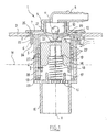
- valve 1 shows in schematic axial section an example of valve 1 according to the invention.
- valve 1 is fixed in an opening 2 of the upper wall 3 of a motor vehicle fuel tank.
- the valve 1 has three cylindrical walls, respectively referenced (of inside to outside) 4, 5 and 6, which are arranged in a baffle as it will be described in more detail below.
- These three walls 4 to 6 are generally symmetrical of revolution around a X axis.
- the radially outermost wall 6 is connected to a flange 7 which is used for fixing the valve 1 on the wall 3 of the tank.
- the collar 7 is extended upwards by a nozzle 8 which is used to connect the valve 1 to a pipe of a venting circuit not shown, comprising a activated carbon filter known per se for recovering fuel vapors.
- the wall 4, radially innermost, is extended superiorly by a neck 9 which forms a housing 10 for a ball 11 whose function will be explained later.
- the housing 10 communicates on the one hand with the end piece 8 and on the other hand, by a orifice 12, with a housing 13 delimited radially by the wall 4, and in which can be move a shutter 14.
- the housing 13 is closed below by a perforated disc 15, on the face upper side of which the wall 5 is connected.
- a tubular skirt 16 is produced under the disc 15, and the latter is perforated to form a nozzle connecting the housing 13 and the interior of this skirt 16.
- An annular rib 17 protrudes from the upper face of the disc 15, to serve as a guide at the lower end of a spring 18 working in compression and the upper end of which abuts against a shoulder 19 of the shutter 14.
- the shutter 14 is provided on its upper face with a stud 20 which serves to mounting a flap 21 capable of closing the orifice 12.
- the flap 21 is mounted with clearance on the stud 20 so as to be able to pivot vertically with respect to this, which makes it possible to detach the flap 21 from the orifice 12 even in the event of an overpressure inside the tank tending to maintain the flap 21 pressed against orifice 12.
- the wall 4 is provided, at its lower end, with a rim 23 directed towards the outside, which serves as a spacer between walls 4 and 5.
- the wall 6 has its lower end 24 which is located above the level N maximum fuel in the tank.
- the annular grooves 25 and 26 respectively formed between the walls 5 and 6 on the one hand and 4 and 5 on the other hand have, in the example described, substantially the same thickness.
- the annular groove 26 communicates with the housing 13 via two groups of orifices 27, diametrically opposite on the wall 4, each constituted by three parallel rows of four holes each, the top row of holes being just below the maximum fuel level N in the tank at rest.
- Two diametrically opposite orifices 28 are further provided at the end. bottom of the wall 4 to allow the liquid fuel contained in the groove 26 to flow into the bottom of the housing 13, under the shutter 14, then to the tank through the disc openings 15.
- the orifices 27 open into the annular space formed between the wall lateral, cylindrical of revolution around the X axis, of the shutter 14 and the surface inside of the wall 4, this annular space having a thickness j of the order of 1 mm in the example described.
- the assembly of the valve is as follows.
- the shutter 14, fitted with the flap 21 retained by the stud 20, is slipped into the wall 4, held upside down.
- Wall 5 is then inserted into wall 4, wall 5 being in the example described comes from molding with the disc 15, the rib 17 and the skirt 16.
- the rim 23 is secured to the wall 5 by any suitable means known to those skilled in the art.
- the walls 5 and 6 overlap over a height of 12 mm.
- the width of each of the grooves 25 and 26 is 2 mm.
- the height of the passage by which the grooves 25 and 26 communicate at the top of the baffle is 2.5 mm.
- the outer diameter of wall 6 is 59 mm, that of wall 5 is 51 mm and that of wall 4 is 43 mm.
- valve 1 The operation of the valve 1 is as follows.
- This filling can only be partial if, as shown in the drawing, a recess 29 is made on the upper edge of the orifice 12 to allow a re-entry of air in the event of vacuum in the tank.
- the shutter 14 compresses by its weight the spring 18, and the flap 21 is located removal of the lower end of the orifice 12.
- the ball 11 maintains a certain overpressure inside during filling of the tank, preventing it from overfilling.
- the ball 11 When rolling, the ball 11 can move away from its seat, allowing a gas flow leaving the tank.
- This baffle prevents droplets of liquid fuel from are entrained inside the housing 13 by the gas flow entering the valve.
- valve 1 the proportion of liquid fuel that leaves valve 1 to the filter activated carbon is considerably reduced compared to the valves of the prior art.
- the shutter 14 serves as an anti-rollover safety device when coming in, when the X axis deviates angularly beyond a predetermined limit of the vertical, close off the orifice 12 to prevent the liquid fuel from reaching the venting circuit.
Abstract
Description
La présente invention concerne un clapet pour réservoir à carburant notamment de
véhicule automobile,
selon le préambule de la revendication 1.The present invention relates to a valve for a fuel tank, in particular of
motor vehicle,
according to the preamble of
Ce type de clapet peut comporter, soit un obturateur mobile s'opposant au départ de carburant liquide par le circuit de mise à l'air libre en cas de retournement accidentel du véhicule -on parle de fonction R.O.V.-, soit un obturateur mobile venant fermer au moins partiellement le circuit de mise à l'air libre lorsque le véhicule est au repos, pour éviter le sur-remplissage et garantir un volume libre d'expansion - on parle de fonction I.S.R. -, soit deux obturateurs mobiles accomplissant respectivement les deux fonctions précitées, soit encore un obturateur mobile unique agencé pour réaliser les deux fonctions ci-dessus à la fois.This type of valve may include either a movable shutter opposing the flow of liquid fuel through the venting system in the event of overturning accidental of the vehicle - we are talking about R.O.V.-, i.e. a mobile shutter coming from at least partially close the venting circuit when the vehicle is at rest, to avoid overfilling and guarantee a free volume of expansion - we talk about I.S.R. -, or two mobile shutters respectively accomplishing the two aforementioned functions, or again a single movable shutter arranged to carry out the two above functions at a time.
Le circuit de mise à l'air libre comporte un filtre à charbons actifs ou analogue pour retenir les vapeurs de carburant et empêcher leur rejet dans l'atmosphère.The venting circuit includes an active carbon filter or the like to retain fuel vapors and prevent their release into the atmosphere.
On connaít par le brevet US 5 687 753 un clapet selon le préambule de la revendication 1 comportant trois parois
coaxiales, pourvues de fentes verticales destinées à récupérer les gouttelettes de carburant
liquide entraínées par l'écoulement gazeux gagnant l'intérieur du clapet.Known from US Patent 5,687,753 a valve according to the preamble of
Un tel clapet est de fabrication relativement complexe.Such a valve is of relatively complex manufacture.
La présente invention a pour objet de prolonger la durée pendant laquelle le filtre est efficace en évitant les remontées de carburant, sous forme de projections.The object of the present invention is to extend the period during which the filter is effective in preventing fuel spillage, in the form of projections.
Elle y parvient par le fait que le logement du clapet dans lequel l'obturateur est retenu communique avec l'environnement gazeux du clapet à l'intérieur du réservoir par l'intermédiaire d'un passage par lequel communiquent deux gorges annulaires, ce passage constituant le sommet d'une chicane obligeant l'écoulement à circuler vers le haut et vers le bas.It achieves this by the fact that the valve housing in which the shutter is retained communicates with the gaseous environment of the valve inside the tank by through a passage through which two annular grooves communicate, this passage constituting the top of a baffle forcing the flow to flow upwards and down.
La société déposante a constaté que grâce à cette configuration particulière du clapet selon l'invention qui oblige l'écoulement à circuler vers le haut et vers le bas, on réduisait fortement la quantité de carburant liquide susceptible d'être entraínée par l'écoulement gazeux jusqu'au filtre. The applicant company noted that thanks to this particular configuration of the valve according to the invention which forces the flow to flow up and down, we greatly reduced the amount of liquid fuel likely to be entrained by gas flow to the filter.
Le clapet selon l'invention est également relativement simple à fabriquer de part sa structure.The valve according to the invention is also relatively simple to manufacture from share its structure.
Dans une réalisation particulière, le clapet comporte trois parois annulaires concentriques disposées en chicane, le logement précité étant défini par la paroi radialement la plus intérieure.In a particular embodiment, the valve has three annular walls concentric arranged in a baffle, the aforementioned housing being defined by the wall radially innermost.
De préférence, la paroi radialement la plus extérieure est venue de moulage avec une collerette servant à la fixation du clapet sur le réservoir.Preferably, the radially outermost wall has come from molding with a flange used to fix the valve on the tank.
De préférence également, cette paroi est dirigée vers le bas et a son extrémité inférieure qui se situe au-dessus du niveau maximum du carburant dans le réservoir lorsque celui-ci est au repos et que le véhicule repose sur une surface horizontale.Preferably also, this wall is directed downwards and at its end below which is above the maximum level of fuel in the tank when it is at rest and the vehicle rests on a horizontal surface.
Dans une réalisation particulière, la chicane communique avec l'intérieur du logement par l'intermédiaire d'un ensemble d'orifices situés sensiblement en regard de la paroi latérale de l'obturateur.In a particular embodiment, the chicane communicates with the interior of the housing through a set of orifices located substantially in look at the side wall of the shutter.
D'autres caractéristiques et avantages de la présente invention apparaítront à la
lecture de la description détaillée qui suit, et à l'examen du dessin annexé sur lequel la
figure 1 représente en coupe axiale schématique un exemple de clapet 1 conforme à
l'invention.Other characteristics and advantages of the present invention will become apparent on
reading the detailed description which follows, and examining the attached drawing on which the
Figure 1 shows in schematic axial section an example of
Comme on le voit sur cette figure, le clapet 1 est fixé dans une ouverture 2 de
la paroi supérieure 3 d'un réservoir de carburant de véhicule automobile.As seen in this figure, the
On a indiqué par un trait discontinu le niveau N maximal du carburant dans le réservoir lorsque ce dernier est au repos et que le véhicule repose sur une surface horizontale.The maximum level N of the fuel in the tank when the latter is at rest and the vehicle rests on a surface horizontal.
Le clapet 1 comporte trois parois cylindriques, respectivement référencées (de
l'intérieur vers l'extérieur) 4, 5 et 6, qui sont disposées en chicane comme cela va être
décrit plus en détail dans la suite.The
Ces trois parois 4 à 6 sont généralement symétriques de révolution autour d'un axe X.These three walls 4 to 6 are generally symmetrical of revolution around a X axis.
La paroi 6, radialement la plus extérieure, se raccorde sur une collerette 7 qui
sert à la fixation du clapet 1 sur la paroi 3 du réservoir.The radially
La collerette 7 est prolongée vers le haut par un embout 8 qui sert à raccorder
le clapet 1 à une tubulure d'un circuit de mise à l'air libre non représenté, comportant un
filtre à charbons actifs connu en soi pour récupérer les vapeurs de carburant. The
La paroi 4, radialement la plus intérieure, est prolongée supérieurement par un
col 9 qui forme un logement 10 pour une bille 11 dont la fonction sera expliquée plus loin.The wall 4, radially innermost, is extended superiorly by a
neck 9 which forms a
Le logement 10 communique d'une part avec l'embout 8 et d'autre part, par un
orifice 12, avec un logement 13 délimité radialement par la paroi 4, et dans lequel peut se
déplacer un obturateur 14.The
Le logement 13 est fermé inférieurement par un disque ajouré 15, sur la face
supérieure duquel se raccorde la paroi 5.The
Une jupe tubulaire 16 est réalisée sous le disque 15, et ce dernier est ajouré
pour constituer un ajutage faisant communiquer le logement 13 et l'intérieur de cette jupe
16.A
Une nervure annulaire 17 forme saillie sur la face supérieure du disque 15,
pour servir de guide à l'extrémité inférieure d'un ressort 18 travaillant en compression et
dont l'extrémité supérieure vient en appui contre un épaulement 19 de l'obturateur 14.An
L'obturateur 14 est muni sur sa face supérieure d'un plot 20 qui sert au
montage d'un volet 21 apte à obturer l'orifice 12.The
Un bossage 22, centré sur l'axe X, est formé sur la face supérieure de
l'obturateur 14, sous le volet 21.A
Le volet 21 est monté avec jeu sur le plot 20 de manière à pouvoir pivoter
verticalement par rapport à celui-ci, ce qui permet d'assurer le décollement du volet 21 de
l'orifice 12 même en cas de surpression à l'intérieur du réservoir tendant à maintenir le
volet 21 plaqué contre l'orifice 12.The
La paroi 4 est munie, à son extrémité inférieure, d'un rebord 23 dirigé vers
l'extérieur, qui sert d'entretoise entre les parois 4 et 5.The wall 4 is provided, at its lower end, with a
La paroi 6 a son extrémité inférieure 24 qui se situe au-dessus du niveau N
maximal de carburant dans le réservoir.The
Les gorges annulaires 25 et 26 respectivement formées entre les parois 5 et 6
d'une part et 4 et 5 d'autre part ont, dans l'exemple décrit, sensiblement la même épaisseur.The
La gorge annulaire 26 communique avec le logement 13 par l'intermédiaire de
deux groupes d'orifices 27, diamétralement opposés sur la paroi 4, constitués chacun par
trois rangées parallèles de quatre trous chacune, la rangée supérieure de trous se situant
juste au-dessous du niveau N maximal de carburant dans le réservoir au repos.The
Deux orifices 28 diamétralement opposés sont en outre prévus à l'extrémité
inférieure de la paroi 4 pour permettre au carburant liquide contenu dans la gorge 26 de
s'écouler dans le bas du logement 13, sous l'obturateur 14, puis vers le réservoir par les
ajours du disque 15.Two diametrically
Les orifices 27 débouchent dans l'espace annulaire formé entre la paroi
latérale, cylindrique de révolution autour de l'axe X, de l'obturateur 14 et la surface
intérieure de la paroi 4, cet espace annulaire ayant une épaisseur j de l'ordre de 1 mm dans
l'exemple décrit.The
L'assemblage du clapet est le suivant.The assembly of the valve is as follows.
On glisse l'obturateur 14, muni du volet 21 retenu par le plot 20, dans la paroi
4, maintenue à l'envers. On insère ensuite la paroi 5 dans la paroi 4, la paroi 5 étant dans
l'exemple décrit venue de moulage avec le disque 15, la nervure 17 et la jupe 16. Le rebord
23 est solidarisé à la paroi 5 par tout moyen approprié connu de l'homme du métier. On
retourne ensuite l'ensemble et l'on place la bille 11 dans le col 9, avant de rapporter
l'embout 8 venu de moulage avec la collerette 7, laquelle peut être fixée à la paroi 3 par
soudure par exemple.The
Dans l'exemple décrit, les parois 5 et 6 se recouvrent sur une hauteur de 12
mm. La largeur de chacune des gorges 25 et 26 vaut 2 mm. La hauteur du passage par
lequel les gorges 25 et 26 communiquent au sommet de la chicane vaut 2,5 mm. Le
diamètre extérieur de la paroi 6 vaut 59 mm, celui de la paroi 5 vaut 51 mm et celui de la
paroi 4 vaut 43 mm.In the example described, the
Le fonctionnement du clapet 1 est le suivant.The operation of the
Au repos, la bille 11 repose dans le fond du logement 10 et obture l'orifice 12.At rest, the
Cette obturation peut être partielle seulement si, comme représenté sur le
dessin, un évidement 29 est réalisé sur le bord supérieur de l'orifice 12 pour permettre une
rentrée d'air en cas de dépression dans le réservoir.This filling can only be partial if, as shown in the
drawing, a
L'obturateur 14 comprime par son poids le ressort 18, et le volet 21 se situe en
retrait de l'extrémité inférieure de l'orifice 12.The
La bille 11 maintient lors du remplissage une certaine surpression à l'intérieur
du réservoir, empêchant son sur-remplissage.The
Lors du roulage, la bille 11 peut s'écarter de son siège, permettant à un
écoulement gazeux de quitter le réservoir.When rolling, the
Tant que le niveau de carburant dans le réservoir dépasse l'extrémité inférieure
de la jupe 16, cet écoulement gazeux doit, pour atteindre le logement 13, circuler par la
chicane formée entre les parois 4,5 et 6 comme illustré par des flèches sur le dessin puis
traverser les orifices 27.As long as the fuel level in the tank exceeds the lower end
of the
Cette chicane permet d'éviter que des gouttelettes de carburant liquide ne
soient entraínées à l'intérieur du logement 13 par l'écoulement gazeux rentrant dans le
clapet.This baffle prevents droplets of liquid fuel from
are entrained inside the
Ainsi, la proportion de carburant liquide qui quitte le clapet 1 vers le filtre à
charbons actifs est considérablement réduite par rapport aux clapets de l'art antérieur.Thus, the proportion of liquid fuel that leaves
L'obturateur 14 sert de sécurité anti-retournement en venant, lorsque l'axe X
s'écarte angulairement au-delà d'une limite prédéterminée de la verticale, obturer l'orifice
12 pour empêcher que le carburant liquide ne gagne le circuit de mise à l'air libre.The
Bien entendu, l'invention n'est pas limitée à l'exemple de réalisation qui vient d'être décrit.Of course, the invention is not limited to the embodiment which comes to be described.
On peut notamment, sans sortir du cadre de l'invention, réaliser les fonctions de sécurité anti-retournement et d'interdiction de sur-remplissage en utilisant des obturateurs autres que ceux qui viennent d'être décrits.We can in particular, without departing from the scope of the invention, perform the functions anti-rollover safety and overfill prevention using shutters other than those just described.
Claims (6)
- Valve (1) for a fuel tank, comprising a shutter (14) that can move in a housing (13) of the valve to at least partially open and close an orifice (12) of the valve, this orifice allowing a gaseous flow to leave the tank towards a vent circuit, said housing (13) communicating with the gaseous environment of the valve within the tank via a passage via which two annular grooves (25, 26) communicate, characterized in that this passage constitutes the top of a chicane (25, 26) forcing the flow to flow upwards and downwards.
- Valve according to Claim 1, characterized in that it comprises three concentric walls (4, 5, 6) arranged in a chicane, the said housing (13) being defined by the radially innermost wall (4).
- Valve according to Claim 2, characterized in that the radially outermost wall (6) is moulded integrally with a flange (7) used to fix the valve (1) on the tank.
- Valve according to Claim 2 or 3, characterized in that the radially outermost wall (6) is directed downwards and has its lower end situated above the maximum level (N) of the fuel in the tank when the tank is at rest.
- Valve according to any one of Claims 1 to 4, characterized in that the said chicane communicates with the inside of the said housing (13) via a set of orifices (27) situated more or less facing the side wall of the shutter.
- Valve according to the preceding claim, characterized in that the said set of orifices comprises two groups of orifices each consisting of three parallel rows of four holes each.
Applications Claiming Priority (2)
| Application Number | Priority Date | Filing Date | Title |
|---|---|---|---|
| FR9809615 | 1998-07-28 | ||
| FR9809615A FR2781728B1 (en) | 1998-07-28 | 1998-07-28 | VALVE FOR A FUEL TANK OF A MOTOR VEHICLE |
Publications (2)
| Publication Number | Publication Date |
|---|---|
| EP0976597A1 EP0976597A1 (en) | 2000-02-02 |
| EP0976597B1 true EP0976597B1 (en) | 2003-08-13 |
Family
ID=9529088
Family Applications (1)
| Application Number | Title | Priority Date | Filing Date |
|---|---|---|---|
| EP99401933A Expired - Lifetime EP0976597B1 (en) | 1998-07-28 | 1999-07-28 | Valve for the fuel tank of a motor vehicle |
Country Status (5)
| Country | Link |
|---|---|
| EP (1) | EP0976597B1 (en) |
| AT (1) | ATE247006T1 (en) |
| BR (1) | BR9902999A (en) |
| DE (1) | DE69910317T2 (en) |
| FR (1) | FR2781728B1 (en) |
Cited By (2)
| Publication number | Priority date | Publication date | Assignee | Title |
|---|---|---|---|---|
| EP1564057A1 (en) | 2004-02-10 | 2005-08-17 | Effbe-France S.A.S. | Valve arrangement including several serially connected valves to prevent fuel losses of vehicle tanks independently of the orientation of the vehicle |
| DE112006001855T5 (en) | 2005-07-15 | 2008-10-30 | Effbe-France S.A.S. | Valve for a container, in particular a fuel tank of a motor vehicle |
Families Citing this family (4)
| Publication number | Priority date | Publication date | Assignee | Title |
|---|---|---|---|---|
| US6779544B2 (en) * | 2001-03-02 | 2004-08-24 | Stant Manufacturing Inc. | Tank refueling shutoff valve and vent system |
| US6990961B2 (en) | 2001-07-31 | 2006-01-31 | Siemens Aktiengesellschaft | Ventilation and areation device for a fuel tank |
| JP3931291B2 (en) | 2001-11-29 | 2007-06-13 | 豊田合成株式会社 | Fuel tank fuel spill regulating device |
| DE10257223A1 (en) * | 2002-12-07 | 2004-06-24 | Volkswagen Ag | Tank valve esp. for motor vehicle fuel tanks has lever valve connected to float body via rotary joint, to close opening of ventilation channel |
Family Cites Families (2)
| Publication number | Priority date | Publication date | Assignee | Title |
|---|---|---|---|---|
| US5449029A (en) * | 1994-05-11 | 1995-09-12 | Stant Manufacturing Inc. | Fill limit valve assembly |
| DE19510821C2 (en) * | 1995-03-24 | 1997-02-13 | Porsche Ag | Fuel tanks for vehicles, in particular motor vehicles |
-
1998
- 1998-07-28 FR FR9809615A patent/FR2781728B1/en not_active Expired - Fee Related
-
1999
- 1999-07-27 BR BR9902999-5A patent/BR9902999A/en not_active IP Right Cessation
- 1999-07-28 AT AT99401933T patent/ATE247006T1/en not_active IP Right Cessation
- 1999-07-28 EP EP99401933A patent/EP0976597B1/en not_active Expired - Lifetime
- 1999-07-28 DE DE69910317T patent/DE69910317T2/en not_active Expired - Lifetime
Cited By (2)
| Publication number | Priority date | Publication date | Assignee | Title |
|---|---|---|---|---|
| EP1564057A1 (en) | 2004-02-10 | 2005-08-17 | Effbe-France S.A.S. | Valve arrangement including several serially connected valves to prevent fuel losses of vehicle tanks independently of the orientation of the vehicle |
| DE112006001855T5 (en) | 2005-07-15 | 2008-10-30 | Effbe-France S.A.S. | Valve for a container, in particular a fuel tank of a motor vehicle |
Also Published As
| Publication number | Publication date |
|---|---|
| BR9902999A (en) | 2000-08-08 |
| FR2781728B1 (en) | 2001-02-16 |
| DE69910317D1 (en) | 2003-09-18 |
| DE69910317T2 (en) | 2004-06-24 |
| EP0976597A1 (en) | 2000-02-02 |
| ATE247006T1 (en) | 2003-08-15 |
| FR2781728A1 (en) | 2000-02-04 |
Similar Documents
| Publication | Publication Date | Title |
|---|---|---|
| EP1079984B1 (en) | Device for ventilating a motor vehicle fuel tank | |
| EP0975482B1 (en) | Fuel tank canister and fuel tank equipped with same | |
| FR2896568A1 (en) | Flow management valve for ventilation valve, has shutter moving in conical part of control chamber between operation and filling positions, where chamber communicates with interior of liquid reservoir, filling head and canister | |
| EP0921025B1 (en) | Fuel tank | |
| EP0340062B1 (en) | Filling limitation device for a fuel tank and automotive vehicle equipped with such a device | |
| FR2739612A1 (en) | APPARATUS FOR CONTROLLING FUEL TANK VESSELS IN A VEHICLE | |
| FR2774951A1 (en) | Fuel tank with vent system assisting filling and preventing excess internal pressure | |
| EP0976597B1 (en) | Valve for the fuel tank of a motor vehicle | |
| FR2886366A1 (en) | LIQUID TANK AIR SUPPLY SYSTEM | |
| EP0774372B1 (en) | Improved venting device for fuel tank for motor vehicle and fuel tank including this device | |
| FR2766014A1 (en) | LEAD ACID ACCUMULATOR, AND CLOSING AND FILTRATION ELEMENTS FOR SUCH AN ACCUMULATOR | |
| EP1112886B1 (en) | Valve for the fuel tank of a motor vehicle | |
| EP1064166B1 (en) | Ventilating device for motor vehicle fuel tank | |
| EP1285805B1 (en) | Multifunctional assembly for fuel system, tank with such an assembly and method of making the system | |
| FR2802481A1 (en) | DEVICE FOR BREAKING DOWN A FUEL TANK | |
| FR2625284A1 (en) | Valve for regulating the pressure inside a fuel tank | |
| FR2606856A1 (en) | SAFETY VALVE FOR FUEL TANKS OF MOTOR VEHICLES | |
| EP0277869B1 (en) | Valve, particularly for venting motor car fuel tanks | |
| FR2669864A1 (en) | Vent valve for a vehicle fuel tank | |
| FR2766134A1 (en) | Safety air inlet for vehicle fuel tank | |
| EP1064167B1 (en) | Ventilating device for motor vehicle fuel tank | |
| FR2774636A1 (en) | Connection of automobile fuel tank to atmosphere to release tank over pressure | |
| FR2750656A1 (en) | Valve for fuel tank | |
| EP0516528B1 (en) | Safety valve for the ventilation of a fuel tank of a motor vehicle | |
| FR2686840A1 (en) | Venting device for a fuel tank |
Legal Events
| Date | Code | Title | Description |
|---|---|---|---|
| PUAI | Public reference made under article 153(3) epc to a published international application that has entered the european phase |
Free format text: ORIGINAL CODE: 0009012 |
|
| AK | Designated contracting states |
Kind code of ref document: A1 Designated state(s): AT BE CH CY DE DK ES FI FR GB GR IE IT LI LU MC NL PT SE |
|
| AX | Request for extension of the european patent |
Free format text: AL;LT;LV;MK;RO;SI |
|
| 17P | Request for examination filed |
Effective date: 20000726 |
|
| AKX | Designation fees paid |
Free format text: AT BE CH CY DE DK ES FI FR GB GR IE IT LI LU MC NL PT SE |
|
| GRAG | Despatch of communication of intention to grant |
Free format text: ORIGINAL CODE: EPIDOS AGRA |
|
| 17Q | First examination report despatched |
Effective date: 20020506 |
|
| GRAG | Despatch of communication of intention to grant |
Free format text: ORIGINAL CODE: EPIDOS AGRA |
|
| GRAG | Despatch of communication of intention to grant |
Free format text: ORIGINAL CODE: EPIDOS AGRA |
|
| GRAH | Despatch of communication of intention to grant a patent |
Free format text: ORIGINAL CODE: EPIDOS IGRA |
|
| GRAH | Despatch of communication of intention to grant a patent |
Free format text: ORIGINAL CODE: EPIDOS IGRA |
|
| GRAH | Despatch of communication of intention to grant a patent |
Free format text: ORIGINAL CODE: EPIDOS IGRA |
|
| GRAH | Despatch of communication of intention to grant a patent |
Free format text: ORIGINAL CODE: EPIDOS IGRA |
|
| GRAA | (expected) grant |
Free format text: ORIGINAL CODE: 0009210 |
|
| AK | Designated contracting states |
Designated state(s): AT BE CH CY DE DK ES FI FR GB GR IE IT LI LU MC NL PT SE |
|
| PG25 | Lapsed in a contracting state [announced via postgrant information from national office to epo] |
Ref country code: NL Free format text: LAPSE BECAUSE OF FAILURE TO SUBMIT A TRANSLATION OF THE DESCRIPTION OR TO PAY THE FEE WITHIN THE PRESCRIBED TIME-LIMIT Effective date: 20030813 Ref country code: IT Free format text: LAPSE BECAUSE OF FAILURE TO SUBMIT A TRANSLATION OF THE DESCRIPTION OR TO PAY THE FEE WITHIN THE PRESCRIBED TIME-LIMIT;WARNING: LAPSES OF ITALIAN PATENTS WITH EFFECTIVE DATE BEFORE 2007 MAY HAVE OCCURRED AT ANY TIME BEFORE 2007. THE CORRECT EFFECTIVE DATE MAY BE DIFFERENT FROM THE ONE RECORDED. Effective date: 20030813 Ref country code: IE Free format text: LAPSE BECAUSE OF FAILURE TO SUBMIT A TRANSLATION OF THE DESCRIPTION OR TO PAY THE FEE WITHIN THE PRESCRIBED TIME-LIMIT Effective date: 20030813 Ref country code: GB Free format text: LAPSE BECAUSE OF FAILURE TO SUBMIT A TRANSLATION OF THE DESCRIPTION OR TO PAY THE FEE WITHIN THE PRESCRIBED TIME-LIMIT Effective date: 20030813 Ref country code: FI Free format text: LAPSE BECAUSE OF FAILURE TO SUBMIT A TRANSLATION OF THE DESCRIPTION OR TO PAY THE FEE WITHIN THE PRESCRIBED TIME-LIMIT Effective date: 20030813 Ref country code: CY Free format text: LAPSE BECAUSE OF FAILURE TO SUBMIT A TRANSLATION OF THE DESCRIPTION OR TO PAY THE FEE WITHIN THE PRESCRIBED TIME-LIMIT Effective date: 20030813 Ref country code: AT Free format text: LAPSE BECAUSE OF FAILURE TO SUBMIT A TRANSLATION OF THE DESCRIPTION OR TO PAY THE FEE WITHIN THE PRESCRIBED TIME-LIMIT Effective date: 20030813 |
|
| REG | Reference to a national code |
Ref country code: GB Ref legal event code: FG4D Free format text: NOT ENGLISH |
|
| REG | Reference to a national code |
Ref country code: CH Ref legal event code: EP |
|
| REG | Reference to a national code |
Ref country code: IE Ref legal event code: FG4D Free format text: FRENCH |
|
| REF | Corresponds to: |
Ref document number: 69910317 Country of ref document: DE Date of ref document: 20030918 Kind code of ref document: P |
|
| PG25 | Lapsed in a contracting state [announced via postgrant information from national office to epo] |
Ref country code: SE Free format text: LAPSE BECAUSE OF FAILURE TO SUBMIT A TRANSLATION OF THE DESCRIPTION OR TO PAY THE FEE WITHIN THE PRESCRIBED TIME-LIMIT Effective date: 20031113 Ref country code: GR Free format text: LAPSE BECAUSE OF FAILURE TO SUBMIT A TRANSLATION OF THE DESCRIPTION OR TO PAY THE FEE WITHIN THE PRESCRIBED TIME-LIMIT Effective date: 20031113 Ref country code: DK Free format text: LAPSE BECAUSE OF FAILURE TO SUBMIT A TRANSLATION OF THE DESCRIPTION OR TO PAY THE FEE WITHIN THE PRESCRIBED TIME-LIMIT Effective date: 20031113 |
|
| PG25 | Lapsed in a contracting state [announced via postgrant information from national office to epo] |
Ref country code: ES Free format text: LAPSE BECAUSE OF FAILURE TO SUBMIT A TRANSLATION OF THE DESCRIPTION OR TO PAY THE FEE WITHIN THE PRESCRIBED TIME-LIMIT Effective date: 20031124 |
|
| PG25 | Lapsed in a contracting state [announced via postgrant information from national office to epo] |
Ref country code: PT Free format text: LAPSE BECAUSE OF FAILURE TO SUBMIT A TRANSLATION OF THE DESCRIPTION OR TO PAY THE FEE WITHIN THE PRESCRIBED TIME-LIMIT Effective date: 20040113 |
|
| NLV1 | Nl: lapsed or annulled due to failure to fulfill the requirements of art. 29p and 29m of the patents act | ||
| GBV | Gb: ep patent (uk) treated as always having been void in accordance with gb section 77(7)/1977 [no translation filed] |
Effective date: 20030813 |
|
| REG | Reference to a national code |
Ref country code: IE Ref legal event code: FD4D |
|
| PLBE | No opposition filed within time limit |
Free format text: ORIGINAL CODE: 0009261 |
|
| STAA | Information on the status of an ep patent application or granted ep patent |
Free format text: STATUS: NO OPPOSITION FILED WITHIN TIME LIMIT |
|
| PG25 | Lapsed in a contracting state [announced via postgrant information from national office to epo] |
Ref country code: LU Free format text: LAPSE BECAUSE OF NON-PAYMENT OF DUE FEES Effective date: 20040728 |
|
| PG25 | Lapsed in a contracting state [announced via postgrant information from national office to epo] |
Ref country code: MC Free format text: LAPSE BECAUSE OF NON-PAYMENT OF DUE FEES Effective date: 20040731 Ref country code: LI Free format text: LAPSE BECAUSE OF NON-PAYMENT OF DUE FEES Effective date: 20040731 Ref country code: CH Free format text: LAPSE BECAUSE OF NON-PAYMENT OF DUE FEES Effective date: 20040731 Ref country code: BE Free format text: LAPSE BECAUSE OF NON-PAYMENT OF DUE FEES Effective date: 20040731 |
|
| 26N | No opposition filed |
Effective date: 20040514 |
|
| BERE | Be: lapsed |
Owner name: CIE *PLASTIC OMNIUM Effective date: 20040731 |
|
| REG | Reference to a national code |
Ref country code: CH Ref legal event code: PL |
|
| REG | Reference to a national code |
Ref country code: FR Ref legal event code: TP |
|
| BERE | Be: lapsed |
Owner name: CIE *PLASTIC OMNIUM Effective date: 20040731 |
|
| PGFP | Annual fee paid to national office [announced via postgrant information from national office to epo] |
Ref country code: FR Payment date: 20140724 Year of fee payment: 16 |
|
| REG | Reference to a national code |
Ref country code: FR Ref legal event code: ST Effective date: 20160331 |
|
| PG25 | Lapsed in a contracting state [announced via postgrant information from national office to epo] |
Ref country code: FR Free format text: LAPSE BECAUSE OF NON-PAYMENT OF DUE FEES Effective date: 20150731 |
|
| PGFP | Annual fee paid to national office [announced via postgrant information from national office to epo] |
Ref country code: DE Payment date: 20180723 Year of fee payment: 20 |
|
| REG | Reference to a national code |
Ref country code: DE Ref legal event code: R071 Ref document number: 69910317 Country of ref document: DE |