EP0976597B1 - Ventil für den Kraftstofftank eines Kraftfahrzeuges - Google Patents
Ventil für den Kraftstofftank eines Kraftfahrzeuges Download PDFInfo
- Publication number
- EP0976597B1 EP0976597B1 EP99401933A EP99401933A EP0976597B1 EP 0976597 B1 EP0976597 B1 EP 0976597B1 EP 99401933 A EP99401933 A EP 99401933A EP 99401933 A EP99401933 A EP 99401933A EP 0976597 B1 EP0976597 B1 EP 0976597B1
- Authority
- EP
- European Patent Office
- Prior art keywords
- valve
- tank
- housing
- wall
- shutter
- Prior art date
- Legal status (The legal status is an assumption and is not a legal conclusion. Google has not performed a legal analysis and makes no representation as to the accuracy of the status listed.)
- Expired - Lifetime
Links
Images
Classifications
-
- B—PERFORMING OPERATIONS; TRANSPORTING
- B60—VEHICLES IN GENERAL
- B60K—ARRANGEMENT OR MOUNTING OF PROPULSION UNITS OR OF TRANSMISSIONS IN VEHICLES; ARRANGEMENT OR MOUNTING OF PLURAL DIVERSE PRIME-MOVERS IN VEHICLES; AUXILIARY DRIVES FOR VEHICLES; INSTRUMENTATION OR DASHBOARDS FOR VEHICLES; ARRANGEMENTS IN CONNECTION WITH COOLING, AIR INTAKE, GAS EXHAUST OR FUEL SUPPLY OF PROPULSION UNITS IN VEHICLES
- B60K15/00—Arrangement in connection with fuel supply of combustion engines or other fuel consuming energy converters, e.g. fuel cells; Mounting or construction of fuel tanks
- B60K15/03—Fuel tanks
- B60K15/035—Fuel tanks characterised by venting means
- B60K15/03519—Valve arrangements in the vent line
Definitions
- the present invention relates to a valve for a fuel tank, in particular of motor vehicle, according to the preamble of claim 1.
- This type of valve may include either a movable shutter opposing the flow of liquid fuel through the venting system in the event of overturning accidental of the vehicle - we are talking about R.O.V.-, i.e. a mobile shutter coming from at least partially close the venting circuit when the vehicle is at rest, to avoid overfilling and guarantee a free volume of expansion - we talk about I.S.R. -, or two mobile shutters respectively accomplishing the two aforementioned functions, or again a single movable shutter arranged to carry out the two above functions at a time.
- a movable shutter opposing the flow of liquid fuel through the venting system in the event of overturning accidental of the vehicle - we are talking about R.O.V.-, i.e. a mobile shutter coming from at least partially close the venting circuit when the vehicle is at rest, to avoid overfilling and guarantee a free volume of expansion - we talk about I.S.R. -, or two mobile shutters respectively accomplishing the two aforementioned functions,
- the venting circuit includes an active carbon filter or the like to retain fuel vapors and prevent their release into the atmosphere.
- valve according to the preamble of claim 1 comprising three walls coaxial, provided with vertical slots for collecting fuel droplets liquid entrained by the gas flow reaching the interior of the valve.
- Such a valve is of relatively complex manufacture.
- the object of the present invention is to extend the period during which the filter is effective in preventing fuel spillage, in the form of projections.
- valve housing in which the shutter is retained communicates with the gaseous environment of the valve inside the tank by through a passage through which two annular grooves communicate, this passage constituting the top of a baffle forcing the flow to flow upwards and down.
- the valve according to the invention is also relatively simple to manufacture from share its structure.
- the valve has three annular walls concentric arranged in a baffle, the aforementioned housing being defined by the wall radially innermost.
- the radially outermost wall has come from molding with a flange used to fix the valve on the tank.
- this wall is directed downwards and at its end below which is above the maximum level of fuel in the tank when it is at rest and the vehicle rests on a horizontal surface.
- the chicane communicates with the interior of the housing through a set of orifices located substantially in look at the side wall of the shutter.
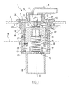
- valve 1 shows in schematic axial section an example of valve 1 according to the invention.
- valve 1 is fixed in an opening 2 of the upper wall 3 of a motor vehicle fuel tank.
- the valve 1 has three cylindrical walls, respectively referenced (of inside to outside) 4, 5 and 6, which are arranged in a baffle as it will be described in more detail below.
- These three walls 4 to 6 are generally symmetrical of revolution around a X axis.
- the radially outermost wall 6 is connected to a flange 7 which is used for fixing the valve 1 on the wall 3 of the tank.
- the collar 7 is extended upwards by a nozzle 8 which is used to connect the valve 1 to a pipe of a venting circuit not shown, comprising a activated carbon filter known per se for recovering fuel vapors.
- the wall 4, radially innermost, is extended superiorly by a neck 9 which forms a housing 10 for a ball 11 whose function will be explained later.
- the housing 10 communicates on the one hand with the end piece 8 and on the other hand, by a orifice 12, with a housing 13 delimited radially by the wall 4, and in which can be move a shutter 14.
- the housing 13 is closed below by a perforated disc 15, on the face upper side of which the wall 5 is connected.
- a tubular skirt 16 is produced under the disc 15, and the latter is perforated to form a nozzle connecting the housing 13 and the interior of this skirt 16.
- An annular rib 17 protrudes from the upper face of the disc 15, to serve as a guide at the lower end of a spring 18 working in compression and the upper end of which abuts against a shoulder 19 of the shutter 14.
- the shutter 14 is provided on its upper face with a stud 20 which serves to mounting a flap 21 capable of closing the orifice 12.
- the flap 21 is mounted with clearance on the stud 20 so as to be able to pivot vertically with respect to this, which makes it possible to detach the flap 21 from the orifice 12 even in the event of an overpressure inside the tank tending to maintain the flap 21 pressed against orifice 12.
- the wall 4 is provided, at its lower end, with a rim 23 directed towards the outside, which serves as a spacer between walls 4 and 5.
- the wall 6 has its lower end 24 which is located above the level N maximum fuel in the tank.
- the annular grooves 25 and 26 respectively formed between the walls 5 and 6 on the one hand and 4 and 5 on the other hand have, in the example described, substantially the same thickness.
- the annular groove 26 communicates with the housing 13 via two groups of orifices 27, diametrically opposite on the wall 4, each constituted by three parallel rows of four holes each, the top row of holes being just below the maximum fuel level N in the tank at rest.
- Two diametrically opposite orifices 28 are further provided at the end. bottom of the wall 4 to allow the liquid fuel contained in the groove 26 to flow into the bottom of the housing 13, under the shutter 14, then to the tank through the disc openings 15.
- the orifices 27 open into the annular space formed between the wall lateral, cylindrical of revolution around the X axis, of the shutter 14 and the surface inside of the wall 4, this annular space having a thickness j of the order of 1 mm in the example described.
- the assembly of the valve is as follows.
- the shutter 14, fitted with the flap 21 retained by the stud 20, is slipped into the wall 4, held upside down.
- Wall 5 is then inserted into wall 4, wall 5 being in the example described comes from molding with the disc 15, the rib 17 and the skirt 16.
- the rim 23 is secured to the wall 5 by any suitable means known to those skilled in the art.
- the walls 5 and 6 overlap over a height of 12 mm.
- the width of each of the grooves 25 and 26 is 2 mm.
- the height of the passage by which the grooves 25 and 26 communicate at the top of the baffle is 2.5 mm.
- the outer diameter of wall 6 is 59 mm, that of wall 5 is 51 mm and that of wall 4 is 43 mm.
- valve 1 The operation of the valve 1 is as follows.
- This filling can only be partial if, as shown in the drawing, a recess 29 is made on the upper edge of the orifice 12 to allow a re-entry of air in the event of vacuum in the tank.
- the shutter 14 compresses by its weight the spring 18, and the flap 21 is located removal of the lower end of the orifice 12.
- the ball 11 maintains a certain overpressure inside during filling of the tank, preventing it from overfilling.
- the ball 11 When rolling, the ball 11 can move away from its seat, allowing a gas flow leaving the tank.
- This baffle prevents droplets of liquid fuel from are entrained inside the housing 13 by the gas flow entering the valve.
- valve 1 the proportion of liquid fuel that leaves valve 1 to the filter activated carbon is considerably reduced compared to the valves of the prior art.
- the shutter 14 serves as an anti-rollover safety device when coming in, when the X axis deviates angularly beyond a predetermined limit of the vertical, close off the orifice 12 to prevent the liquid fuel from reaching the venting circuit.
Landscapes
- Engineering & Computer Science (AREA)
- Life Sciences & Earth Sciences (AREA)
- Sustainable Development (AREA)
- Sustainable Energy (AREA)
- Chemical & Material Sciences (AREA)
- Combustion & Propulsion (AREA)
- Transportation (AREA)
- Mechanical Engineering (AREA)
- Cooling, Air Intake And Gas Exhaust, And Fuel Tank Arrangements In Propulsion Units (AREA)
- Self-Closing Valves And Venting Or Aerating Valves (AREA)
- Output Control And Ontrol Of Special Type Engine (AREA)
Claims (6)
- Ventil (1) für einen Kraftstoffbehälter, das ein bewegliches Schließteil (14) in einem Sitz (13) des Ventils aufweist, um eine Öffnung (12) des Ventils schließen und zumindest teilweise zu öffnen, diese Öffnung ermöglicht es einem gasförmigen Ausfluss, den Behälter über eine Lüftungsvorrichtung zu verlassen, dabei befindet sich der Sitz (13) in Kommunikation mit der gasförmigen Umgebung des Ventils im Inneren des Behälters über einen Kanal, durch welchen zwei Ringnuten (25, 26) kommunizieren, dadurch gekennzeichnet, dass der Kanal den obersten Bereich einer Schikane (25, 26) bildet, die den Ausfluss zwingt, nach oben und nach unten zu zirkulieren.
- Ventil nach Anspruch 1, dadurch gekennzeichnet, dass es drei konzentrische Wände (4, 5, 6) aufweist, die eine Schikane bildend angeordnet sind und dass der Sitz (13) durch die radial am weitesten innen liegende Wand (4) definiert ist.
- Ventil nach Anspruch 2, dadurch gekennzeichnet, dass die radial am weitesten außen liegende Wand (6) im Spritzgussverfahren zusammen mit einem Kragen (7) hergestellt ist, der der Befestigung des Ventils (1) an dem Behälter dient.
- Ventil nach Anspruch 2 oder 3, dadurch gekennzeichnet, dass die radial am weitesten außen liegende Wand (6) nach unten gerichtet ist und einen unteren Endbereich aufweist, der sich oberhalb des maximalen Niveaus (N) des Kraftstoffs in dem Behälter befindet, wenn dieser im Ruhezustand ist.
- Ventil nach einem beliebigen der Ansprüche 1 bis 4, dadurch gekennzeichnet, dass die Schikane mittels eines Satzes von Öffnungen (27) mit dem Inneren des Sitzes (13) kommuniziert, die im Wesentlichen der Seitenwand des Schließorgans gegenüber liegend angeordnet sind.
- Ventil nach einem der vorangegangenen Ansprüche, dadurch gekennzeichnet, dass der genannte Satz von Öffnungen zwei Gruppen von Öffnungen aufweist, die jeweils durch drei parallele Reihen von jeweils vier Bohrungen gebildet sind.
Applications Claiming Priority (2)
| Application Number | Priority Date | Filing Date | Title |
|---|---|---|---|
| FR9809615 | 1998-07-28 | ||
| FR9809615A FR2781728B1 (fr) | 1998-07-28 | 1998-07-28 | Clapet pour reservoir a carburant de vehicule automobile |
Publications (2)
| Publication Number | Publication Date |
|---|---|
| EP0976597A1 EP0976597A1 (de) | 2000-02-02 |
| EP0976597B1 true EP0976597B1 (de) | 2003-08-13 |
Family
ID=9529088
Family Applications (1)
| Application Number | Title | Priority Date | Filing Date |
|---|---|---|---|
| EP99401933A Expired - Lifetime EP0976597B1 (de) | 1998-07-28 | 1999-07-28 | Ventil für den Kraftstofftank eines Kraftfahrzeuges |
Country Status (5)
| Country | Link |
|---|---|
| EP (1) | EP0976597B1 (de) |
| AT (1) | ATE247006T1 (de) |
| BR (1) | BR9902999A (de) |
| DE (1) | DE69910317T2 (de) |
| FR (1) | FR2781728B1 (de) |
Cited By (2)
| Publication number | Priority date | Publication date | Assignee | Title |
|---|---|---|---|---|
| EP1564057A1 (de) | 2004-02-10 | 2005-08-17 | Effbe-France S.A.S. | Ventil-Anordnung mit mehreren in Reihe geschalteten Ventilen zur Verhinderung eines Kraftstoffausfliessens bei Fahrzeugtanks unabhängig von der Orientierung des Fahrzeugs |
| DE112006001855T5 (de) | 2005-07-15 | 2008-10-30 | Effbe-France S.A.S. | Ventil für einen Behälter, insbesondere einen Kraftstoffbehälter eines Kraftfahrzeugs |
Families Citing this family (4)
| Publication number | Priority date | Publication date | Assignee | Title |
|---|---|---|---|---|
| US6779544B2 (en) | 2001-03-02 | 2004-08-24 | Stant Manufacturing Inc. | Tank refueling shutoff valve and vent system |
| US6990961B2 (en) | 2001-07-31 | 2006-01-31 | Siemens Aktiengesellschaft | Ventilation and areation device for a fuel tank |
| JP3931291B2 (ja) | 2001-11-29 | 2007-06-13 | 豊田合成株式会社 | 燃料タンクの燃料流出規制装置 |
| DE10257223A1 (de) * | 2002-12-07 | 2004-06-24 | Volkswagen Ag | Tankventil |
Family Cites Families (2)
| Publication number | Priority date | Publication date | Assignee | Title |
|---|---|---|---|---|
| US5449029A (en) * | 1994-05-11 | 1995-09-12 | Stant Manufacturing Inc. | Fill limit valve assembly |
| DE19510821C2 (de) * | 1995-03-24 | 1997-02-13 | Porsche Ag | Kraftstoffbehälter für Fahrzeuge, insbesondere Kraftfahrzeuge |
-
1998
- 1998-07-28 FR FR9809615A patent/FR2781728B1/fr not_active Expired - Fee Related
-
1999
- 1999-07-27 BR BR9902999-5A patent/BR9902999A/pt not_active IP Right Cessation
- 1999-07-28 DE DE69910317T patent/DE69910317T2/de not_active Expired - Lifetime
- 1999-07-28 EP EP99401933A patent/EP0976597B1/de not_active Expired - Lifetime
- 1999-07-28 AT AT99401933T patent/ATE247006T1/de not_active IP Right Cessation
Cited By (2)
| Publication number | Priority date | Publication date | Assignee | Title |
|---|---|---|---|---|
| EP1564057A1 (de) | 2004-02-10 | 2005-08-17 | Effbe-France S.A.S. | Ventil-Anordnung mit mehreren in Reihe geschalteten Ventilen zur Verhinderung eines Kraftstoffausfliessens bei Fahrzeugtanks unabhängig von der Orientierung des Fahrzeugs |
| DE112006001855T5 (de) | 2005-07-15 | 2008-10-30 | Effbe-France S.A.S. | Ventil für einen Behälter, insbesondere einen Kraftstoffbehälter eines Kraftfahrzeugs |
Also Published As
| Publication number | Publication date |
|---|---|
| DE69910317D1 (de) | 2003-09-18 |
| FR2781728B1 (fr) | 2001-02-16 |
| BR9902999A (pt) | 2000-08-08 |
| DE69910317T2 (de) | 2004-06-24 |
| FR2781728A1 (fr) | 2000-02-04 |
| ATE247006T1 (de) | 2003-08-15 |
| EP0976597A1 (de) | 2000-02-02 |
Similar Documents
| Publication | Publication Date | Title |
|---|---|---|
| EP1079984B1 (de) | Entlüftungsvorrichtung eines kraftstofftanks eines kraftfahrzeuges | |
| EP0975482B1 (de) | Behälter für kraftstofftank und kraftstofftank mit einem solchen behälter | |
| EP0921025B1 (de) | Kraftstofftank | |
| FR2739612A1 (fr) | Appareil de commande de vapeurs de reservoir de carcurant d'un vehicule | |
| EP0340062B1 (de) | Füllbegrenzungsvorrichtung für einen Brennstofftank und ein Kraftfahrzeug mit einer solchen Vorrichtung | |
| FR2896568A1 (fr) | Dispositif pour circuit de mise a l'air d'un reservoir a liquide et clapet integrant ledit dispositif | |
| EP0976597B1 (de) | Ventil für den Kraftstofftank eines Kraftfahrzeuges | |
| FR2954805A1 (fr) | Clapet pour circuit de mise a l'air d'un reservoir a liquide | |
| EP0774372B1 (de) | Verbesserte Tankentlüftungsvorrichtung für Kraftfahrzeugtank und Kraftfahrzeugtank mit dieser Vorrichtung | |
| FR2889489A1 (fr) | Soupape de ventilation pour le reservoir a carburant dans des vehicules automobiles. | |
| FR2831875A1 (fr) | Bouchon de reservoir | |
| FR2766014A1 (fr) | Accumulateur acide au plomb, et elements de fermeture et de filtration pour un tel accumulateur | |
| EP1112886B1 (de) | Ventil für den Kraftstofftank eines Kraftfahrzeuges | |
| EP1064166B1 (de) | Entlüftungsvorrichtung für den kraftstofftank eines kraftfahrzeuges | |
| EP1285805B1 (de) | Multifunktionseinheit in einem Kraftstoffsystem, Tank mit einer solchen Einheit und Verfahren zur Herstellung des Systems | |
| FR2802481A1 (fr) | Dispositif de mise a l'air libre d'un reservoir de carburant | |
| FR2886366A1 (fr) | Systeme de mise a l'air de reservoir a liquide | |
| EP3661793B1 (de) | Druckregelvorrichtung und verfahren für ihren zusammenbau, für einen kraftstoffdampffilter | |
| FR2606856A1 (fr) | Soupape de surete pour reservoirs de carburant de vehicules automobiles | |
| EP0277869B1 (de) | Ventil, insbesondere für die Entlüftung von Autobrennstofftanks | |
| FR2669864A1 (fr) | Clapet de ventilation pour un reservoir de carburant d'un vehicule. | |
| FR2766134A1 (fr) | Dispositif de mise a l'air libre et de securite pour un reservoir de carburant de vehicule automobile | |
| EP1064167B1 (de) | Entlüftungsvorrichtung für den kraftstofftank eines kraftfahrzeuges | |
| FR2731260A1 (fr) | Soupape d'equilibre de pression pour un reservoir de carburant | |
| FR2774636A1 (fr) | Dispositif de mise a l'air libre d'un reservoir de carburant de vehicule automobile |
Legal Events
| Date | Code | Title | Description |
|---|---|---|---|
| PUAI | Public reference made under article 153(3) epc to a published international application that has entered the european phase |
Free format text: ORIGINAL CODE: 0009012 |
|
| AK | Designated contracting states |
Kind code of ref document: A1 Designated state(s): AT BE CH CY DE DK ES FI FR GB GR IE IT LI LU MC NL PT SE |
|
| AX | Request for extension of the european patent |
Free format text: AL;LT;LV;MK;RO;SI |
|
| 17P | Request for examination filed |
Effective date: 20000726 |
|
| AKX | Designation fees paid |
Free format text: AT BE CH CY DE DK ES FI FR GB GR IE IT LI LU MC NL PT SE |
|
| GRAG | Despatch of communication of intention to grant |
Free format text: ORIGINAL CODE: EPIDOS AGRA |
|
| 17Q | First examination report despatched |
Effective date: 20020506 |
|
| GRAG | Despatch of communication of intention to grant |
Free format text: ORIGINAL CODE: EPIDOS AGRA |
|
| GRAG | Despatch of communication of intention to grant |
Free format text: ORIGINAL CODE: EPIDOS AGRA |
|
| GRAH | Despatch of communication of intention to grant a patent |
Free format text: ORIGINAL CODE: EPIDOS IGRA |
|
| GRAH | Despatch of communication of intention to grant a patent |
Free format text: ORIGINAL CODE: EPIDOS IGRA |
|
| GRAH | Despatch of communication of intention to grant a patent |
Free format text: ORIGINAL CODE: EPIDOS IGRA |
|
| GRAH | Despatch of communication of intention to grant a patent |
Free format text: ORIGINAL CODE: EPIDOS IGRA |
|
| GRAA | (expected) grant |
Free format text: ORIGINAL CODE: 0009210 |
|
| AK | Designated contracting states |
Designated state(s): AT BE CH CY DE DK ES FI FR GB GR IE IT LI LU MC NL PT SE |
|
| PG25 | Lapsed in a contracting state [announced via postgrant information from national office to epo] |
Ref country code: NL Free format text: LAPSE BECAUSE OF FAILURE TO SUBMIT A TRANSLATION OF THE DESCRIPTION OR TO PAY THE FEE WITHIN THE PRESCRIBED TIME-LIMIT Effective date: 20030813 Ref country code: IT Free format text: LAPSE BECAUSE OF FAILURE TO SUBMIT A TRANSLATION OF THE DESCRIPTION OR TO PAY THE FEE WITHIN THE PRESCRIBED TIME-LIMIT;WARNING: LAPSES OF ITALIAN PATENTS WITH EFFECTIVE DATE BEFORE 2007 MAY HAVE OCCURRED AT ANY TIME BEFORE 2007. THE CORRECT EFFECTIVE DATE MAY BE DIFFERENT FROM THE ONE RECORDED. Effective date: 20030813 Ref country code: IE Free format text: LAPSE BECAUSE OF FAILURE TO SUBMIT A TRANSLATION OF THE DESCRIPTION OR TO PAY THE FEE WITHIN THE PRESCRIBED TIME-LIMIT Effective date: 20030813 Ref country code: GB Free format text: LAPSE BECAUSE OF FAILURE TO SUBMIT A TRANSLATION OF THE DESCRIPTION OR TO PAY THE FEE WITHIN THE PRESCRIBED TIME-LIMIT Effective date: 20030813 Ref country code: FI Free format text: LAPSE BECAUSE OF FAILURE TO SUBMIT A TRANSLATION OF THE DESCRIPTION OR TO PAY THE FEE WITHIN THE PRESCRIBED TIME-LIMIT Effective date: 20030813 Ref country code: CY Free format text: LAPSE BECAUSE OF FAILURE TO SUBMIT A TRANSLATION OF THE DESCRIPTION OR TO PAY THE FEE WITHIN THE PRESCRIBED TIME-LIMIT Effective date: 20030813 Ref country code: AT Free format text: LAPSE BECAUSE OF FAILURE TO SUBMIT A TRANSLATION OF THE DESCRIPTION OR TO PAY THE FEE WITHIN THE PRESCRIBED TIME-LIMIT Effective date: 20030813 |
|
| REG | Reference to a national code |
Ref country code: GB Ref legal event code: FG4D Free format text: NOT ENGLISH |
|
| REG | Reference to a national code |
Ref country code: CH Ref legal event code: EP |
|
| REG | Reference to a national code |
Ref country code: IE Ref legal event code: FG4D Free format text: FRENCH |
|
| REF | Corresponds to: |
Ref document number: 69910317 Country of ref document: DE Date of ref document: 20030918 Kind code of ref document: P |
|
| PG25 | Lapsed in a contracting state [announced via postgrant information from national office to epo] |
Ref country code: SE Free format text: LAPSE BECAUSE OF FAILURE TO SUBMIT A TRANSLATION OF THE DESCRIPTION OR TO PAY THE FEE WITHIN THE PRESCRIBED TIME-LIMIT Effective date: 20031113 Ref country code: GR Free format text: LAPSE BECAUSE OF FAILURE TO SUBMIT A TRANSLATION OF THE DESCRIPTION OR TO PAY THE FEE WITHIN THE PRESCRIBED TIME-LIMIT Effective date: 20031113 Ref country code: DK Free format text: LAPSE BECAUSE OF FAILURE TO SUBMIT A TRANSLATION OF THE DESCRIPTION OR TO PAY THE FEE WITHIN THE PRESCRIBED TIME-LIMIT Effective date: 20031113 |
|
| PG25 | Lapsed in a contracting state [announced via postgrant information from national office to epo] |
Ref country code: ES Free format text: LAPSE BECAUSE OF FAILURE TO SUBMIT A TRANSLATION OF THE DESCRIPTION OR TO PAY THE FEE WITHIN THE PRESCRIBED TIME-LIMIT Effective date: 20031124 |
|
| PG25 | Lapsed in a contracting state [announced via postgrant information from national office to epo] |
Ref country code: PT Free format text: LAPSE BECAUSE OF FAILURE TO SUBMIT A TRANSLATION OF THE DESCRIPTION OR TO PAY THE FEE WITHIN THE PRESCRIBED TIME-LIMIT Effective date: 20040113 |
|
| NLV1 | Nl: lapsed or annulled due to failure to fulfill the requirements of art. 29p and 29m of the patents act | ||
| GBV | Gb: ep patent (uk) treated as always having been void in accordance with gb section 77(7)/1977 [no translation filed] |
Effective date: 20030813 |
|
| REG | Reference to a national code |
Ref country code: IE Ref legal event code: FD4D |
|
| PLBE | No opposition filed within time limit |
Free format text: ORIGINAL CODE: 0009261 |
|
| STAA | Information on the status of an ep patent application or granted ep patent |
Free format text: STATUS: NO OPPOSITION FILED WITHIN TIME LIMIT |
|
| PG25 | Lapsed in a contracting state [announced via postgrant information from national office to epo] |
Ref country code: LU Free format text: LAPSE BECAUSE OF NON-PAYMENT OF DUE FEES Effective date: 20040728 |
|
| PG25 | Lapsed in a contracting state [announced via postgrant information from national office to epo] |
Ref country code: MC Free format text: LAPSE BECAUSE OF NON-PAYMENT OF DUE FEES Effective date: 20040731 Ref country code: LI Free format text: LAPSE BECAUSE OF NON-PAYMENT OF DUE FEES Effective date: 20040731 Ref country code: CH Free format text: LAPSE BECAUSE OF NON-PAYMENT OF DUE FEES Effective date: 20040731 Ref country code: BE Free format text: LAPSE BECAUSE OF NON-PAYMENT OF DUE FEES Effective date: 20040731 |
|
| 26N | No opposition filed |
Effective date: 20040514 |
|
| BERE | Be: lapsed |
Owner name: CIE *PLASTIC OMNIUM Effective date: 20040731 |
|
| REG | Reference to a national code |
Ref country code: CH Ref legal event code: PL |
|
| REG | Reference to a national code |
Ref country code: FR Ref legal event code: TP |
|
| BERE | Be: lapsed |
Owner name: CIE *PLASTIC OMNIUM Effective date: 20040731 |
|
| PGFP | Annual fee paid to national office [announced via postgrant information from national office to epo] |
Ref country code: FR Payment date: 20140724 Year of fee payment: 16 |
|
| REG | Reference to a national code |
Ref country code: FR Ref legal event code: ST Effective date: 20160331 |
|
| PG25 | Lapsed in a contracting state [announced via postgrant information from national office to epo] |
Ref country code: FR Free format text: LAPSE BECAUSE OF NON-PAYMENT OF DUE FEES Effective date: 20150731 |
|
| PGFP | Annual fee paid to national office [announced via postgrant information from national office to epo] |
Ref country code: DE Payment date: 20180723 Year of fee payment: 20 |
|
| REG | Reference to a national code |
Ref country code: DE Ref legal event code: R071 Ref document number: 69910317 Country of ref document: DE |