EP0340062B1 - Füllbegrenzungsvorrichtung für einen Brennstofftank und ein Kraftfahrzeug mit einer solchen Vorrichtung - Google Patents
Füllbegrenzungsvorrichtung für einen Brennstofftank und ein Kraftfahrzeug mit einer solchen Vorrichtung Download PDFInfo
- Publication number
- EP0340062B1 EP0340062B1 EP19890400961 EP89400961A EP0340062B1 EP 0340062 B1 EP0340062 B1 EP 0340062B1 EP 19890400961 EP19890400961 EP 19890400961 EP 89400961 A EP89400961 A EP 89400961A EP 0340062 B1 EP0340062 B1 EP 0340062B1
- Authority
- EP
- European Patent Office
- Prior art keywords
- magnet
- valve
- flap
- support
- vehicle
- Prior art date
- Legal status (The legal status is an assumption and is not a legal conclusion. Google has not performed a legal analysis and makes no representation as to the accuracy of the status listed.)
- Expired - Lifetime
Links
- 239000002828 fuel tank Substances 0.000 title claims description 9
- 238000013022 venting Methods 0.000 claims description 16
- 238000004891 communication Methods 0.000 claims description 7
- 239000000696 magnetic material Substances 0.000 claims description 5
- 238000006073 displacement reaction Methods 0.000 claims description 4
- 230000005484 gravity Effects 0.000 claims description 3
- 230000000284 resting effect Effects 0.000 claims description 2
- 239000000446 fuel Substances 0.000 description 13
- 239000007789 gas Substances 0.000 description 9
- 239000007788 liquid Substances 0.000 description 4
- 208000031968 Cadaver Diseases 0.000 description 3
- 230000000694 effects Effects 0.000 description 3
- 238000004519 manufacturing process Methods 0.000 description 3
- 238000007872 degassing Methods 0.000 description 2
- 238000001704 evaporation Methods 0.000 description 2
- 230000008020 evaporation Effects 0.000 description 2
- 229910000831 Steel Inorganic materials 0.000 description 1
- 241001080024 Telles Species 0.000 description 1
- 230000006835 compression Effects 0.000 description 1
- 238000007906 compression Methods 0.000 description 1
- 238000009833 condensation Methods 0.000 description 1
- 230000005494 condensation Effects 0.000 description 1
- 238000010276 construction Methods 0.000 description 1
- 235000021183 entrée Nutrition 0.000 description 1
- 238000007789 sealing Methods 0.000 description 1
- 238000000926 separation method Methods 0.000 description 1
- 239000010959 steel Substances 0.000 description 1
- 238000009423 ventilation Methods 0.000 description 1
Images

Classifications
-
- F—MECHANICAL ENGINEERING; LIGHTING; HEATING; WEAPONS; BLASTING
- F16—ENGINEERING ELEMENTS AND UNITS; GENERAL MEASURES FOR PRODUCING AND MAINTAINING EFFECTIVE FUNCTIONING OF MACHINES OR INSTALLATIONS; THERMAL INSULATION IN GENERAL
- F16K—VALVES; TAPS; COCKS; ACTUATING-FLOATS; DEVICES FOR VENTING OR AERATING
- F16K17/00—Safety valves; Equalising valves, e.g. pressure relief valves
- F16K17/36—Safety valves; Equalising valves, e.g. pressure relief valves actuated in consequence of extraneous circumstances, e.g. shock, change of position
-
- B—PERFORMING OPERATIONS; TRANSPORTING
- B60—VEHICLES IN GENERAL
- B60K—ARRANGEMENT OR MOUNTING OF PROPULSION UNITS OR OF TRANSMISSIONS IN VEHICLES; ARRANGEMENT OR MOUNTING OF PLURAL DIVERSE PRIME-MOVERS IN VEHICLES; AUXILIARY DRIVES FOR VEHICLES; INSTRUMENTATION OR DASHBOARDS FOR VEHICLES; ARRANGEMENTS IN CONNECTION WITH COOLING, AIR INTAKE, GAS EXHAUST OR FUEL SUPPLY OF PROPULSION UNITS IN VEHICLES
- B60K15/00—Arrangement in connection with fuel supply of combustion engines or other fuel consuming energy converters, e.g. fuel cells; Mounting or construction of fuel tanks
- B60K15/03—Fuel tanks
- B60K15/035—Fuel tanks characterised by venting means
- B60K15/03519—Valve arrangements in the vent line
-
- B—PERFORMING OPERATIONS; TRANSPORTING
- B60—VEHICLES IN GENERAL
- B60K—ARRANGEMENT OR MOUNTING OF PROPULSION UNITS OR OF TRANSMISSIONS IN VEHICLES; ARRANGEMENT OR MOUNTING OF PLURAL DIVERSE PRIME-MOVERS IN VEHICLES; AUXILIARY DRIVES FOR VEHICLES; INSTRUMENTATION OR DASHBOARDS FOR VEHICLES; ARRANGEMENTS IN CONNECTION WITH COOLING, AIR INTAKE, GAS EXHAUST OR FUEL SUPPLY OF PROPULSION UNITS IN VEHICLES
- B60K15/00—Arrangement in connection with fuel supply of combustion engines or other fuel consuming energy converters, e.g. fuel cells; Mounting or construction of fuel tanks
- B60K15/03—Fuel tanks
- B60K15/04—Tank inlets
Definitions
- the subject of the invention is a device for limiting the filling of a fuel tank, in particular for motor vehicles, intended to prevent fuel from entering the expansion volume of the tank during filling thereof.
- a ventilation circuit is generally provided allowing the evacuation into the atmosphere of part of the gases contained in the expansion volume in the event of overpressure. This overpressure may be due to the expansion of the gases under the effect of heat, to their compression under the effect of the expansion of the fuel or to the evaporation of the latter.
- the invention overcomes these drawbacks by proposing a device for limiting the filling of a fuel tank, in particular for a motor vehicle, which makes it possible to reduce the number of elements linked to the tank.
- the device of the invention applies to a tank having an upper part in which is formed an expansion volume communicating with the outside by a venting circuit and a lower part in which opens the lower end a filling tube, the upper end of which is situated in the vicinity of a hatch formed in the vehicle body and movable between a closed position and an open position.
- this device comprises means for closing the venting circuit controlled by the hatch and closing the venting circuit when the latter is in the open position; according to the invention, these shutter means are arranged to automatically shut off the venting circuit in the event of the vehicle overturning.
- At least part of the valve is made of a magnetic material and the means for moving the valve include a magnet fixed on a magnet support mounted on the structure of the vehicle, this support being movable, under the action of the hatch, between a rest position when the hatch is in the closed position and a working position when the hatch is in the open position, the magnet being placed so as to attract the valve in the working position when the support of magnet is itself in the working position.
- the magnet being placed outside the housing, it attracts the ball when it is approached from a side wall of the latter.
- the ball moves upward due to the concavity of the upper face of the support and pushes the bell-shaped part towards the top of the housing so that the boss penetrates into the outlet orifice and causes it to be closed.
- the housing is preferably cylindrical with a vertical axis and the external dimensions of the bell-shaped part are close to the internal dimensions of the housing so that this part can only carry out translational movements along the axis of the housing.
- the ball rolls on the upper face of the support and pushes the bell-shaped part towards the outlet orifice: it is therefore understandable that from a certain inclination, the displacement of this part is sufficient to seal the outlet and prevent the flow of fuel through the venting system.
- These means for rotating include a rigid rod secured to the rotating body, a portion of the hatch coming into contact with this rod and moving it when the hatch goes from the closed position to the open position.
- the arm is of elongated shape and carries the magnet at its end furthest from the axis of rotation of the body: the magnet tends to return the arm to the vertical position by gravity, thus constituting the means of recall.
- the return means comprise a spring having a first end fixed to the structure of the vehicle and a second end fixed to said arm.
- the spring can also be used in the first embodiment to ensure a safer and faster return to the rest position.
- the invention also relates to a motor vehicle equipped with a device for limiting the filling of the fuel tank as described above.
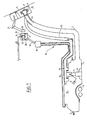
- a tank can have a complex shape because we are looking to have the maximum volume for the fuel as a function of the space available between different elements, such as for example the passage of the muffler 3.
- a suction pump 4 Inside the tank is mounted a suction pump 4, the lower part of which is surrounded by a fuel trap 5 provided on the bottom of the tank.
- a gauge 6 which, in the example shown here, consists of a float attached to the end of a lever mounted on the pump 4 and movable in rotation about a horizontal axis.
- a filling tube 7 opens at the lower part of the tank by one of its ends while its other end is closed by a removable plug 8. This is located in a housing 9, provided in the body 10 of the vehicle, this housing can be closed by a mobile hatch 11.
- a degassing tube 12 connecting the upper part of the tank to the upper part of the filling pipe.
- a deflector 13 is mounted in the vicinity of the upper end of the tube 7 to prevent the introduction of fuel into the degassing tube 12.
- an expansion volume 14 has been provided at the upper part thereof.
- a venting circuit 15 connects the volume of expansion 14 outside to allow the evacuation of the gas contained therein in the event of overpressure.
- the circuit 15 first comprises two vent tubes 16 and 17, one end of which opens into the expansion volume 14 while their other end opens into the lower part of a venting capacity 18.
- the role of this capacity 18 is to allow the separation of the drops of fuel which could have been entrained with the gas in the tubes 16 and 17 or the condensation of part of the vapors, and the return of the liquid in the tank.
- the venting capacity 18 can have for example a volume of 0.5 liters for an internal diameter of the tubes 16 and 17 of 3.5 mm and a useful volume of the tank of 80 liters, the expansion volume being about 6 liters.
- the lower part of the capacity 18 must be above the upper part of the tank.
- two tubes 16 and 17 are provided which open respectively at two opposite ends of the expansion volume 14 so that the gases can always be evacuated: thus, even if the vehicle leans to one side, causing liquid entering one of the tubes, the other tube will always lead to the gas pocket.
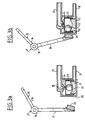
- a tube 19 connects the upper part of the capacity 18 to the lower part of a housing 20 located above the capacity 18 and placed in the vicinity of the hatch and which contains a ball valve.
- the latter consists of a support 21, fixed to the housing, having a concave upper face on which freely rests a ball 22 made of magnetic material. This is surmounted by a bell-shaped part 23 which has a boss 24 on its upper face. This boss has a shape such that it can block an outlet orifice provided in the upper part of the housing 20. This orifice is the starting point of a tube 25 which places the housing 20 in communication with the outside or with a device such as a canister for example.
- the ball 22 may for example be made of steel, and the housing 20, as well as the support 21, the part 23 and the tubes 19 and 25, made of plastic.
- the valve is controlled by a magnet 26 mounted on a magnet support 27 itself controlled by the opening movement of the hatch 11.
- the magnet support 27 essentially consists of a cylindrical body 30 mounted on the structure of the vehicle and movable freely in rotation around its axis which is substantially horizontal.
- an arm 31 which carries the magnet 26 at its end furthest from the body 30.
- a rigid rod 32 secured to the rotating body 30 has a first part 33 whose axis coincides with that of the body 30, then bends and has a second part 34 directed upwards.
- FIG. 3b The working position of the magnet holder is shown in Figure 3b. In relation to the position of Figure 3a, it has pivoted anticlockwise and the magnet 26 is in contact with the side wall of the housing 20. It therefore attracts the ball 22 which moves laterally. During this movement, it is raised since the upper face of the support 21 is concave and has its edges located higher than the center. This has the effect of lifting the bell-shaped part 23 and the boss 24 closes the orifice 35.
- the housing 20 is preferably cylindrical and of vertical axis and the external diameter of the part 23 is slightly less than the internal diameter of the housing.
- the part 23 can only move in translation along the axis of the cylinder and it is certain that the boss 24 will close the orifice 35 at each lifting of the part 23.
- an elastic means may be provided such as a spring (not shown) fixed on the one hand to the structure of the vehicle and on the other hand to the arm 31 to return the latter in a safe manner to the rest position when the flap is closed.
- a spring (not shown) fixed on the one hand to the structure of the vehicle and on the other hand to the arm 31 to return the latter in a safe manner to the rest position when the flap is closed.
- the housing 20 also serves to prevent the flow of fuel through the venting circuit in the event of overturning or overturning the vehicle. Indeed, if the latter takes an excessive inclination, as the support 21 is fixed relative to the housing 20, the ball rolls to reach the lowest point of the upper face of the support, which is no longer the central point as in Figure 3a. This movement therefore causes the displacement of the part 23 towards the orifice 35 and the obturation thereof if the inclination of the vehicle exceeds a certain value. It is the same if the vehicle overturns, the ball then leaving the support 21 and pushing the part 23 by gravity.
- the invention has particularly interesting advantages since it is the same device, controlled by the hatch, which ensures the closure of the venting circuit while the hatch is open and prevents the flow of fuel by the venting circuit in the event of the vehicle overturning: its construction is simplified and its manufacturing cost reduced.
Landscapes
- Engineering & Computer Science (AREA)
- Mechanical Engineering (AREA)
- Life Sciences & Earth Sciences (AREA)
- Sustainable Development (AREA)
- Sustainable Energy (AREA)
- Chemical & Material Sciences (AREA)
- Combustion & Propulsion (AREA)
- Transportation (AREA)
- General Engineering & Computer Science (AREA)
- Cooling, Air Intake And Gas Exhaust, And Fuel Tank Arrangements In Propulsion Units (AREA)
Claims (10)
Applications Claiming Priority (2)
| Application Number | Priority Date | Filing Date | Title |
|---|---|---|---|
| FR8805585 | 1988-04-27 | ||
| FR8805585A FR2630686B1 (fr) | 1988-04-27 | 1988-04-27 | Dispositif de limitation de remplissage d'un reservoir de carburant et vehicule automobile equipe d'un tel dispositif |
Publications (2)
| Publication Number | Publication Date |
|---|---|
| EP0340062A1 EP0340062A1 (de) | 1989-11-02 |
| EP0340062B1 true EP0340062B1 (de) | 1991-06-12 |
Family
ID=9365727
Family Applications (1)
| Application Number | Title | Priority Date | Filing Date |
|---|---|---|---|
| EP19890400961 Expired - Lifetime EP0340062B1 (de) | 1988-04-27 | 1989-04-07 | Füllbegrenzungsvorrichtung für einen Brennstofftank und ein Kraftfahrzeug mit einer solchen Vorrichtung |
Country Status (5)
| Country | Link |
|---|---|
| EP (1) | EP0340062B1 (de) |
| JP (1) | JPH0211420A (de) |
| DE (1) | DE68900115D1 (de) |
| ES (1) | ES2022757B3 (de) |
| FR (1) | FR2630686B1 (de) |
Cited By (1)
| Publication number | Priority date | Publication date | Assignee | Title |
|---|---|---|---|---|
| DE102010023473A1 (de) | 2010-06-11 | 2011-12-15 | Dr. Ing. H.C. F. Porsche Aktiengesellschaft | Verfahren zum Betreiiben eines Kraftfahrzeugs und Kraftfahrzeug |
Families Citing this family (19)
| Publication number | Priority date | Publication date | Assignee | Title |
|---|---|---|---|---|
| GB2239006B (en) * | 1989-12-12 | 1993-10-06 | Ford Motor Co | A fuel filler arrangement |
| FR2661969B1 (fr) * | 1990-05-11 | 1992-10-02 | Transformat Mat Plastiques | Clapet de securite notamment pour une canalisation de mise a l'air d'un reservoir a carburant. |
| US5247958A (en) * | 1990-05-11 | 1993-09-28 | Solvay & Cie | Safety valve, especially for a fuel tank vent pipe |
| FR2668987B1 (fr) * | 1990-11-14 | 1995-07-07 | Transformat Mat Plastiques | Dispositif de securite pour circuit d'alimentation en carburant du reservoir d'un vehicule automobile. |
| FR2668986A1 (fr) * | 1990-11-14 | 1992-05-15 | Transformat Mat Plastiques | Dispositif de securite pour circuit d'alimentation en carburant du reservoir d'un vehicule automobile. |
| FR2668988B1 (fr) * | 1990-11-14 | 1993-02-12 | Transformat Mat Plastiques | Dispositif de securite pour circuit d'alimentation en carburant du reservoir d'un vehicule automobile. |
| FR2692207B1 (fr) * | 1992-06-11 | 1994-08-12 | Peugeot | Dispositif d'aération d'un réservoir de carburant d'un véhicule automobile. |
| FR2695358B1 (fr) * | 1992-09-07 | 1994-12-02 | Peugeot | Dispositif d'évacuation des gaz formés dans un réservoir de carburant de véhicule automobile. |
| DE19509889A1 (de) * | 1994-04-25 | 1995-10-26 | Ford Werke Ag | Magnetisch betätigbares Entflüftungsventil für Kraftstofftanks sowie Einrichtung zum Ablassen und Speichern von Kraftstoffdampf |
| FR2724603B1 (fr) * | 1994-09-16 | 1997-01-17 | Renault | Dispositif de controle de l'evaporation du carburant contenu dans un reservoir |
| FR2725942B1 (fr) * | 1994-10-21 | 1996-11-29 | Renault | Dispositif de limitation de l'evaporation du carburant contenu dans un reservoir |
| FR2759643B1 (fr) * | 1997-02-14 | 1999-05-14 | Peugeot | Dispositif de remplissage d'un reservoir a carburant, notamment de vehicule automobile |
| DE19905110C1 (de) * | 1999-02-09 | 2000-10-26 | Alfmeier Praezision Ag | Ventil zur Entlüftung eines Kraftstofftanks |
| DE10336345A1 (de) * | 2003-08-08 | 2005-03-03 | Bayerische Motoren Werke Ag | Entlüftungseinrichtung für einen Kraftstoffbehälter eines Kraftfahrzeugs |
| DE102007001545A1 (de) * | 2007-01-10 | 2008-07-17 | Bayerische Motoren Werke Aktiengesellschaft | Verfahren zum Befüllen eines Kraftstofftanks eines Kraftfahrzeugs sowie System zur Durchführung dieses Verfahrens |
| GB2467519A (en) * | 2009-01-29 | 2010-08-04 | Agco Gmbh | Fluid tank with vents allowing tilting |
| DE102011108333B4 (de) * | 2011-07-25 | 2014-11-20 | Kautex Textron Gmbh & Co. Kg | Flüssigkeitsbehälter für ein KFZ, insbesondere ein Kraftstoffbehälter |
| KR102463408B1 (ko) * | 2016-03-16 | 2022-11-03 | 현대자동차주식회사 | 차량의 연료탱크 밴팅 시스템 |
| FR3124765A1 (fr) | 2021-07-01 | 2023-01-06 | Psa Automobiles Sa | Systeme de reservoir de carburant de vehicule automobile avec canalisation de degazage |
Family Cites Families (6)
| Publication number | Priority date | Publication date | Assignee | Title |
|---|---|---|---|---|
| GB1241070A (en) * | 1968-10-28 | 1971-07-28 | John Leroy Follett | Shut off valve |
| SE402076B (sv) * | 1975-02-21 | 1978-06-19 | Saab Scania Ab | Ventilmekanism vid pafyllningsror till vetskebehallare |
| JPS60199727A (ja) * | 1984-03-24 | 1985-10-09 | Toyota Motor Corp | 車両用燃料タンク |
| FR2581597B1 (fr) * | 1985-05-07 | 1990-03-09 | Renault | Dispositif de limitation de remplissage d'un reservoir a carburant, notamment pour vehicule automobile |
| DE3664120D1 (en) * | 1985-10-23 | 1989-08-03 | Journee Paul Sa | Security venting device against the excess filling of fuel tanks |
| FR2598981B3 (fr) * | 1986-05-21 | 1988-07-15 | Renault | Trappe de remplissage, notamment pour reservoirs de carburant de vehicules automobiles. |
-
1988
- 1988-04-27 FR FR8805585A patent/FR2630686B1/fr not_active Expired - Fee Related
-
1989
- 1989-04-07 DE DE8989400961T patent/DE68900115D1/de not_active Expired - Fee Related
- 1989-04-07 ES ES89400961T patent/ES2022757B3/es not_active Expired - Lifetime
- 1989-04-07 EP EP19890400961 patent/EP0340062B1/de not_active Expired - Lifetime
- 1989-04-26 JP JP10709289A patent/JPH0211420A/ja active Pending
Cited By (1)
| Publication number | Priority date | Publication date | Assignee | Title |
|---|---|---|---|---|
| DE102010023473A1 (de) | 2010-06-11 | 2011-12-15 | Dr. Ing. H.C. F. Porsche Aktiengesellschaft | Verfahren zum Betreiiben eines Kraftfahrzeugs und Kraftfahrzeug |
Also Published As
| Publication number | Publication date |
|---|---|
| FR2630686B1 (fr) | 1991-07-12 |
| ES2022757B3 (es) | 1991-12-01 |
| EP0340062A1 (de) | 1989-11-02 |
| DE68900115D1 (de) | 1991-07-18 |
| FR2630686A1 (fr) | 1989-11-03 |
| JPH0211420A (ja) | 1990-01-16 |
Similar Documents
| Publication | Publication Date | Title |
|---|---|---|
| EP0340062B1 (de) | Füllbegrenzungsvorrichtung für einen Brennstofftank und ein Kraftfahrzeug mit einer solchen Vorrichtung | |
| EP1172306B1 (de) | Entlüftungssystem für Flüssigkeitstank | |
| BE1012390A3 (fr) | Systeme de mise a l'air de reservoir a liquide. | |
| EP0254631B1 (de) | Entlüftungsvorrichtung für Brennstofftank | |
| FR2739612A1 (fr) | Appareil de commande de vapeurs de reservoir de carcurant d'un vehicule | |
| EP0975484A1 (de) | Kraftstofftank mit entlüftungssystem | |
| EP0962684A1 (de) | Sicherheitsventil für einen Flüssigkeitsbehälter | |
| FR2889489A1 (fr) | Soupape de ventilation pour le reservoir a carburant dans des vehicules automobiles. | |
| EP0803394B1 (de) | Kraftstoff-Zufuhrvorrichtung in einem Stautopf und mit dieser Vorrichtung ausgestattetes Kraftfahrzeug | |
| EP0333549B1 (de) | Vorrichtung für die Entlüftung und zum Vermeiden des Ueberfüllens eines Tanks | |
| EP0459866B1 (de) | Einrichtung für den Belüftungskreislauf eines Kraftstofftanks | |
| FR2625284A1 (fr) | Valve de regulation de la pression a l'interieur d'un reservoir de carburant | |
| FR2626955A1 (fr) | Dispositif a soupapes pour un conduit d'aeration et desaeration partant d'un reservoir de carburant | |
| FR2886366A1 (fr) | Systeme de mise a l'air de reservoir a liquide | |
| EP0976597B1 (de) | Ventil für den Kraftstofftank eines Kraftfahrzeuges | |
| FR2583004A1 (fr) | Collecteur a carburant dispose dans un reservoir a carburant comme reserve de carburant de fonctionnement pour un moteur a combustion | |
| FR2698829A1 (fr) | Réservoir à carburant à deux cuves pour véhicule automobile. | |
| FR2669864A1 (fr) | Clapet de ventilation pour un reservoir de carburant d'un vehicule. | |
| EP0872412B1 (de) | Lüftungssystem für einen Raum eines Schiffes | |
| FR2563336A1 (fr) | Dispositif amortisseur pour un flotteur de jauge dispose dans un reservoir de vehicule automobile | |
| FR2686840A1 (fr) | Dispositif d'aeration pour reservoir de carburant. | |
| CH625017A5 (de) | ||
| FR2905745A1 (fr) | Systeme de mise a l'air de reservoir a liquide. | |
| EP0774373B1 (de) | Vorrichtung zum Betanken des Kraftstoffbehälters eines Kraftfahrzeuges | |
| FR2653074A1 (fr) | Dispositif a refouler le carburant dans un reservoir d'automobile. |
Legal Events
| Date | Code | Title | Description |
|---|---|---|---|
| PUAI | Public reference made under article 153(3) epc to a published international application that has entered the european phase |
Free format text: ORIGINAL CODE: 0009012 |
|
| AK | Designated contracting states |
Kind code of ref document: A1 Designated state(s): DE ES GB IT |
|
| 17P | Request for examination filed |
Effective date: 19891128 |
|
| 17Q | First examination report despatched |
Effective date: 19901031 |
|
| GRAA | (expected) grant |
Free format text: ORIGINAL CODE: 0009210 |
|
| AK | Designated contracting states |
Kind code of ref document: B1 Designated state(s): DE ES GB IT |
|
| ITF | It: translation for a ep patent filed | ||
| REF | Corresponds to: |
Ref document number: 68900115 Country of ref document: DE Date of ref document: 19910718 |
|
| GBT | Gb: translation of ep patent filed (gb section 77(6)(a)/1977) | ||
| PLBE | No opposition filed within time limit |
Free format text: ORIGINAL CODE: 0009261 |
|
| STAA | Information on the status of an ep patent application or granted ep patent |
Free format text: STATUS: NO OPPOSITION FILED WITHIN TIME LIMIT |
|
| 26N | No opposition filed | ||
| REG | Reference to a national code |
Ref country code: GB Ref legal event code: IF02 |
|
| PGFP | Annual fee paid to national office [announced via postgrant information from national office to epo] |
Ref country code: GB Payment date: 20030327 Year of fee payment: 15 |
|
| PGFP | Annual fee paid to national office [announced via postgrant information from national office to epo] |
Ref country code: ES Payment date: 20030414 Year of fee payment: 15 |
|
| PGFP | Annual fee paid to national office [announced via postgrant information from national office to epo] |
Ref country code: DE Payment date: 20030630 Year of fee payment: 15 |
|
| PG25 | Lapsed in a contracting state [announced via postgrant information from national office to epo] |
Ref country code: GB Free format text: LAPSE BECAUSE OF NON-PAYMENT OF DUE FEES Effective date: 20040407 |
|
| PG25 | Lapsed in a contracting state [announced via postgrant information from national office to epo] |
Ref country code: ES Free format text: LAPSE BECAUSE OF NON-PAYMENT OF DUE FEES Effective date: 20040410 |
|
| PG25 | Lapsed in a contracting state [announced via postgrant information from national office to epo] |
Ref country code: DE Free format text: LAPSE BECAUSE OF NON-PAYMENT OF DUE FEES Effective date: 20041103 |
|
| GBPC | Gb: european patent ceased through non-payment of renewal fee | ||
| PG25 | Lapsed in a contracting state [announced via postgrant information from national office to epo] |
Ref country code: IT Free format text: LAPSE BECAUSE OF NON-PAYMENT OF DUE FEES Effective date: 20050407 |
|
| REG | Reference to a national code |
Ref country code: ES Ref legal event code: FD2A Effective date: 20040410 |