EP1064166B1 - Ventilating device for motor vehicle fuel tank - Google Patents
Ventilating device for motor vehicle fuel tank Download PDFInfo
- Publication number
- EP1064166B1 EP1064166B1 EP99910440A EP99910440A EP1064166B1 EP 1064166 B1 EP1064166 B1 EP 1064166B1 EP 99910440 A EP99910440 A EP 99910440A EP 99910440 A EP99910440 A EP 99910440A EP 1064166 B1 EP1064166 B1 EP 1064166B1
- Authority
- EP
- European Patent Office
- Prior art keywords
- cup
- fact
- communication
- open air
- valve
- Prior art date
- Legal status (The legal status is an assumption and is not a legal conclusion. Google has not performed a legal analysis and makes no representation as to the accuracy of the status listed.)
- Expired - Lifetime
Links
Images
Classifications
-
- B—PERFORMING OPERATIONS; TRANSPORTING
- B60—VEHICLES IN GENERAL
- B60K—ARRANGEMENT OR MOUNTING OF PROPULSION UNITS OR OF TRANSMISSIONS IN VEHICLES; ARRANGEMENT OR MOUNTING OF PLURAL DIVERSE PRIME-MOVERS IN VEHICLES; AUXILIARY DRIVES FOR VEHICLES; INSTRUMENTATION OR DASHBOARDS FOR VEHICLES; ARRANGEMENTS IN CONNECTION WITH COOLING, AIR INTAKE, GAS EXHAUST OR FUEL SUPPLY OF PROPULSION UNITS IN VEHICLES
- B60K15/00—Arrangement in connection with fuel supply of combustion engines or other fuel consuming energy converters, e.g. fuel cells; Mounting or construction of fuel tanks
- B60K15/03—Fuel tanks
- B60K15/035—Fuel tanks characterised by venting means
- B60K15/03519—Valve arrangements in the vent line
-
- F—MECHANICAL ENGINEERING; LIGHTING; HEATING; WEAPONS; BLASTING
- F16—ENGINEERING ELEMENTS AND UNITS; GENERAL MEASURES FOR PRODUCING AND MAINTAINING EFFECTIVE FUNCTIONING OF MACHINES OR INSTALLATIONS; THERMAL INSULATION IN GENERAL
- F16K—VALVES; TAPS; COCKS; ACTUATING-FLOATS; DEVICES FOR VENTING OR AERATING
- F16K17/00—Safety valves; Equalising valves, e.g. pressure relief valves
- F16K17/36—Safety valves; Equalising valves, e.g. pressure relief valves actuated in consequence of extraneous circumstances, e.g. shock, change of position
-
- Y—GENERAL TAGGING OF NEW TECHNOLOGICAL DEVELOPMENTS; GENERAL TAGGING OF CROSS-SECTIONAL TECHNOLOGIES SPANNING OVER SEVERAL SECTIONS OF THE IPC; TECHNICAL SUBJECTS COVERED BY FORMER USPC CROSS-REFERENCE ART COLLECTIONS [XRACs] AND DIGESTS
- Y10—TECHNICAL SUBJECTS COVERED BY FORMER USPC
- Y10T—TECHNICAL SUBJECTS COVERED BY FORMER US CLASSIFICATION
- Y10T137/00—Fluid handling
- Y10T137/0753—Control by change of position or inertia of system
- Y10T137/0874—Vent opening or closing on tipping container
-
- Y—GENERAL TAGGING OF NEW TECHNOLOGICAL DEVELOPMENTS; GENERAL TAGGING OF CROSS-SECTIONAL TECHNOLOGIES SPANNING OVER SEVERAL SECTIONS OF THE IPC; TECHNICAL SUBJECTS COVERED BY FORMER USPC CROSS-REFERENCE ART COLLECTIONS [XRACs] AND DIGESTS
- Y10—TECHNICAL SUBJECTS COVERED BY FORMER USPC
- Y10T—TECHNICAL SUBJECTS COVERED BY FORMER US CLASSIFICATION
- Y10T137/00—Fluid handling
- Y10T137/8593—Systems
- Y10T137/86292—System with plural openings, one a gas vent or access opening
- Y10T137/86324—Tank with gas vent and inlet or outlet
Definitions
- the invention relates to a venting device for a motor vehicle fuel tank.
- the invention relates more particularly to a device for venting for a motor vehicle fuel tank, of the type in which a valve is provided with a counterweight which is arranged in a chamber into which an inlet opens connected to the tank and an outlet, and of the type in which, when the vehicle is stationary in a substantially horizontal position, the under the effect of its weight, the valve obstructs the valve, and in which, under the effect of the vibrations generated during the setting running or driving the vehicle, the flyweight causes the opening of the valve and the venting of the tank.
- a device for venting for a motor vehicle fuel tank of the type in which a valve is provided with a counterweight which is arranged in a chamber into which an inlet opens connected to the tank and an outlet
- a counterweight which is arranged in a chamber into which an inlet opens connected to the tank and an outlet
- the flyweight causes the opening of the valve and the venting of the tank.
- the flyweight is generally made in the form of a spherical ball which rolls on a surface concave frusto-conical flared upward arranged on a wall lower horizontal of the valve chamber.
- the center of the surface frustoconical is formed by the orifice which is intended to be closed directly by the ball.
- the ball When the vehicle is stationary in position substantially horizontal, the ball, by simple gravity, rests in the center of the frustoconical surface by which it is supported in a circle.
- the sealing of the obturation produced by the ball is conditioned by the correct geometry on the one hand of the ball and, on the other part, of the frustoconical surface. Indeed, in the event of a geometric defect, the contact between the ball and the frustoconical surface does not take place on the entire length of the theoretical contact circle.
- the object of the invention is therefore to propose a new design of a venting device that can achieve simple and economical way a seal between the tank fuel and open air.
- the invention provides a venting device free for a motor vehicle fuel tank, of the type in which a valve is provided with a counterweight which is arranged in a room into which an inlet opening connected to the tank and an outlet, and of the type in which, when the vehicle is stationary in a substantially horizontal position, the counterweight causes, under the effect of its weight, the obturation of the valve, and in which, under the effect of vibrations generated during start-up or the rolling of the vehicle, the counterweight causes the opening of the valve and the venting of the tank, characterized in that the counterweight is supported on a concave upper face of a cup of which a lower face comprises sealing means which are capable of cooperating with a seat formed in a valve body to close one of the valve orifices when the cup is maintained in a closed position by the counterweight in position of stable equilibrium at the bottom of the upper concave surface, and in this that when the flyweight is moved from its stable equilibrium position by vibrations, it causes the cup to tip over so as to interrupt the
- vehicle fuel tanks automobile are generally provided with a venting device free which includes in particular a vent pipe whose a lower portion opens into the tank, at a point top of it, and an upper portion of which is for example connected to a vapor recovery and filtering device.
- a valve is interposed between the lower and upper portions of the pipeline in the open air.
- the venting device compensates for the lower fuel level in the tank allowing the air intake inside the tank so that the prevailing pressure in this one is substantially constant.
- this device in order to avoid any deformation of the tank likely to cause its rupture, this device must also allow the evacuation of gases which would, for example, be compressed due to a temperature rise.
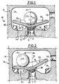
- the venting device 10 which is illustrated in the Figures 1 and 2 partially therefore includes a valve 12 allowing such a closure of the venting circuit when the vehicle is stationary.
- the valve 12 has a chamber 14 which is provided with minus an inlet 16 and an outlet 18.
- the inlet 16, which is arranged through a lower horizontal wall 19 which delimits the chamber 14, is delimited by an internal cylindrical surface 17 of axis A1 and it is for example connected to the fuel tank.
- the outlet 18 opens as for example in a wall side of the chamber 14 or in an upper wall thereof.
- the orifice of outlet 16 is intended to be closed by a cup 20 which is likely to switch between a closed position, illustrated in Figure 1, and an open position, illustrated in Figure 2, under the action a counterweight or ball 22 which is supported under the effect of its weight, on an upper face 24 of the cup 20.
- the cup 20 has substantially a conical shape of A1 axis revolution when the assembly occupies its closed position illustrated in figure 1.
- the upper face 24 of the cup 20 is therefore conical concave, flared upwards at a half-angle at the top ⁇ .
- the face lower 26 of the cup 20 is substantially parallel to the face upper 24 so that the cup 20 has substantially the form of a conical plate of constant thickness.
- the face lower 26 carries, in its center, a boss 28 of which one face lower 30 is flat and horizontal so as to form a span.
- the lower wall 19 of the valve 12 has, substantially in its center, a frustoconical surface 32, of axis A1, which is convex, flared down and raised in relation to the upper face 34 of the wall 18.
- the intersection of the cylindrical surface 17 with the frustoconical surface 32 of the wall lower 18 forms a seat 36 on which is intended to come to rest the inner surface 30 of the bearing surface 20.
- the seat 36 formed at the intersection of two surfaces which have between they an acute angle, can be either in the form of a lip circular, either in the form of an annular chamfer of axis A1.
- the contact between the seat 36 and the bearing surface 30 therefore takes place either in a circle or in a ring.
- the diameter of these two contact surfaces is much less than the transverse dimension of the chamber 14 and the cup 20.
- the counterweight 22 is moved away from its stable equilibrium position, i.e. if it is displaced radially outward relative to the axis A1 of the surface greater than 24 by a distance greater than the radius of the surfaces of contact 30, 36, the weight of ball 22, much greater than that of cup 20, tends to tilt the latter towards a position which is illustrated in FIG. 2 in which the surface of scope 30 is detached from seat 36 except at one point.
- the circulation of gas through valve 12, to the outside or inside of the tank, is then free.
- stops 38 which rise from the upper face 34 of the wall lower 18 of the chamber 14 so as to limit the angle of tilting of the cup 20.
- the stops 38 are intended to cooperate with the radial edge external of the cup 20 and they are arranged at a higher level at the seat 36. More specifically, the stops 38 are arranged in such a way that, when the cup 20 is in the open position, the radius of the upper surface 24 thereof which has the most low slope still has a sufficient slope depending on the direction centripetal so that the flyweight 32 again tends to regain the center of upper surface 24.
- the cup 20 is provided with centering means. which keep it substantially centered along the A1 axis so that when the counterweight 22 is received in the center of the upper face 24, the action of the counterweight 22 on the cup 20 brings it back necessarily in its closed position illustrated in Figure 1. In effect, the thrust exerted by the weight of the counterweight 22 on the cup 20 must then be arranged so as to be inside the circle defined by seat 36.
- the centering means are constituted by a series of fins 40 which extend in relief downwards from the lower surface 30, in the center of it.
- the fins 40 are arranged according to a network of planes vertical perpendicular to each other, the fins 40 also being entirely included within a theoretical envelope surface centered on axis A1.
- the diameter of the spherical envelope is substantially equal to that of the internal cylindrical surface 17 delimiting the orifice 16 so that, when the cup 20 is in the closed position, the fins 40 ensure perfect centering of the cup 20 along the axis A1.
- the fins 40 remain at least partially engaged inside of the orifice 16 but, not having a continuous surface, they do not can oppose the free passage of gases through orifice 16 which can thus be evacuated from the tank to the outside.
- the lateral surface which delimits the chamber 14 presents, in section along a transverse plane perpendicular to the axis A1, a profile corresponding to that of the outer peripheral edge of the cup 20.
- the counterweight 22 preferably has a shape substantially spherical but, unlike the device according to art previous, this sphere does not have to be geometrically perfect.
- the tightness of the valve 12 is determined by the contact between the seat 36 and the bearing surface 30 of the cup 20.
- These parts for example made of plastic molding, can very easily have sufficient geometry to ensure a very good seal.
- the cup 20 can be made of a material rubbery on the one hand perfect the tightness of the contact with the seat and, on the other hand, considerably reduce the noise likely to be caused by successive tilting of the cup.
- the cup 20 can also be produced in a rigid material fully or partially coated with a material rubbery.
- the design of the sealing means of the valve 12 which has just been described can be used in devices for venting incorporating other functions. Especially, this design can be used in venting devices free in which the counterweight 22 also has the function of closing a needle in the event of the vehicle overturning.
Landscapes
- Engineering & Computer Science (AREA)
- Mechanical Engineering (AREA)
- General Engineering & Computer Science (AREA)
- Life Sciences & Earth Sciences (AREA)
- Sustainable Development (AREA)
- Sustainable Energy (AREA)
- Chemical & Material Sciences (AREA)
- Combustion & Propulsion (AREA)
- Transportation (AREA)
- Cooling, Air Intake And Gas Exhaust, And Fuel Tank Arrangements In Propulsion Units (AREA)
- Self-Closing Valves And Venting Or Aerating Valves (AREA)
Description
L'invention concerne un dispositif de mise à l'air libre pour un réservoir de carburant de véhicule automobile.The invention relates to a venting device for a motor vehicle fuel tank.
L'invention se rapporte plus particulièrement à un dispositif de mise à l'air libre pour un réservoir de carburant de véhicule automobile, du type dans lequel une valve est munie d'une masselotte qui est agencée dans une chambre dans laquelle débouchent un orifice d'entrée relié au réservoir et un orifice de sortie, et du type dans lequel, lorsque le véhicule est à l'arrêt en position sensiblement horizontale, la masselotte provoque, sous l'effet de son poids, l'obturation de la valve, et dans lequel, sous l'effet des vibrations engendrées lors de la mise en marche ou du roulage du véhicule, la masselotte provoque l'ouverture de la valve et la mise à l'air libre du réservoir. Un tel dispositif est connu de FR-A-2 740 402.The invention relates more particularly to a device for venting for a motor vehicle fuel tank, of the type in which a valve is provided with a counterweight which is arranged in a chamber into which an inlet opens connected to the tank and an outlet, and of the type in which, when the vehicle is stationary in a substantially horizontal position, the under the effect of its weight, the valve obstructs the valve, and in which, under the effect of the vibrations generated during the setting running or driving the vehicle, the flyweight causes the opening of the valve and the venting of the tank. Such a device is known from FR-A-2 740 402.
Dans les dispositifs connus, la masselotte est généralement réalisée sous la forme d'une bille sphérique qui roule sur une surface tronconique concave évasée vers le haut aménagée sur une paroi horizontale inférieure de la chambre de la valve. Le centre de la surface tronconique est formé par l'orifice qui est destiné à être obturé directement par la bille.In known devices, the flyweight is generally made in the form of a spherical ball which rolls on a surface concave frusto-conical flared upward arranged on a wall lower horizontal of the valve chamber. The center of the surface frustoconical is formed by the orifice which is intended to be closed directly by the ball.
En effet, lorsque le véhicule est à l'arrêt en position sensiblement horizontale, la bille, par simple gravité, repose au centre de la surface tronconique par laquelle elle est en appui selon un cercle.When the vehicle is stationary in position substantially horizontal, the ball, by simple gravity, rests in the center of the frustoconical surface by which it is supported in a circle.
Ainsi, l'étanchéité de l'obturation réalisée par la bille est conditionnée par la bonne géométrie d'une part de la bille et, d'autre part, de la surface tronconique. En effet, en cas de défaut géométrique, le contact entre la bille et la surface tronconique ne s'effectue pas sur toute la longueur du cercle théorique de contact.Thus, the sealing of the obturation produced by the ball is conditioned by the correct geometry on the one hand of the ball and, on the other part, of the frustoconical surface. Indeed, in the event of a geometric defect, the contact between the ball and the frustoconical surface does not take place on the entire length of the theoretical contact circle.
L'invention a donc pour objet de proposer une nouvelle conception d'un dispositif de mise à l'air libre qui puisse réaliser de manière simple et économique une étanchéité entre le réservoir de carburant et l'air libre.The object of the invention is therefore to propose a new design of a venting device that can achieve simple and economical way a seal between the tank fuel and open air.
Dans ce but, l'invention propose un dispositif de mise à l'air libre pour un réservoir de carburant de véhicule automobile, du type dans lequel une valve est munie d'une masselotte qui est agencée dans une chambre dans laquelle débouchent un orifice d'entrée relié au réservoir et un orifice de sortie, et du type dans lequel, lorsque le véhicule est à l'arrêt en position sensiblement horizontale, la masselotte provoque, sous l'effet de son poids, l'obturation de la valve, et dans lequel, sous l'effet des vibrations engendrées lors de la mise en marche ou du roulage du véhicule, la masselotte provoque l'ouverture de la valve et la mise à l'air libre du réservoir, caractérisé en ce que la masselotte est en appui sur une face supérieure concave d'une coupelle dont une face inférieure comporte des moyens d'obturation qui sont susceptibles de coopérer avec un siège formé dans un corps de valve pour obturer l'un des orifices de la valve lorsque la coupelle est maintenue dans une position d'obturation par la masselotte en position d'équilibre stable au fond de la surface concave supérieure, et en ce que, lorsque la masselotte est écartée de sa position d'équilibre stable par des vibrations, elle provoque un basculement de la coupelle de manière à interrompre la coopération des moyens d'obturation avec le siège et ainsi à provoquer l'ouverture de la valve.To this end, the invention provides a venting device free for a motor vehicle fuel tank, of the type in which a valve is provided with a counterweight which is arranged in a room into which an inlet opening connected to the tank and an outlet, and of the type in which, when the vehicle is stationary in a substantially horizontal position, the counterweight causes, under the effect of its weight, the obturation of the valve, and in which, under the effect of vibrations generated during start-up or the rolling of the vehicle, the counterweight causes the opening of the valve and the venting of the tank, characterized in that the counterweight is supported on a concave upper face of a cup of which a lower face comprises sealing means which are capable of cooperating with a seat formed in a valve body to close one of the valve orifices when the cup is maintained in a closed position by the counterweight in position of stable equilibrium at the bottom of the upper concave surface, and in this that when the flyweight is moved from its stable equilibrium position by vibrations, it causes the cup to tip over so as to interrupt the cooperation of the sealing means with the seat and thus cause the valve to open.
Selon d'autres caractéristiques de l'invention :
- la coupelle est sensiblement de forme conique et d'axe vertical ;
- la face inférieure de la coupelle comporte une portée annulaire plane qui, en position d'obturation de la coupelle, coopère avec un siège annulaire formé autour de l'un des orifices qui est aménagé dans une paroi horizontale inférieure de la chambre ;
- le siège est surélevé par rapport à une face supérieure de la paroi inférieure de la chambre ;
- le siège est formé par l'intersection d'une surface cylindrique interne verticale, qui délimite l'orifice à obturer, avec une surface tronconique convexe qui est tournée vers le haut, qui est coaxiale à la surface cylindrique, et qui s'étend au-dessus de la face supérieure de la paroi inférieure de la chambre ;
- la coupelle comporte un centreur qui s'étend vers le bas au travers de l'orifice à obturer et qui, au moins lorsque la coupelle est en position d'obturation, coopère avec un bord de l'orifice pour centrer la coupelle ;
- le centreur s'étend au centre de la portée annulaire ;
- la chambre comporte des moyens de butée qui limitent l'angle de basculement de la coupelle.
- the cup is substantially conical in shape and of vertical axis;
- the underside of the cup has a flat annular surface which, in the closed position of the cup, cooperates with an annular seat formed around one of the orifices which is arranged in a lower horizontal wall of the chamber;
- the seat is raised relative to an upper face of the lower wall of the chamber;
- the seat is formed by the intersection of a vertical internal cylindrical surface, which delimits the orifice to be closed, with a convex frustoconical surface which is turned upwards, which is coaxial with the cylindrical surface, and which extends to the above the upper face of the lower wall of the chamber;
- the cup comprises a centering device which extends downwards through the orifice to be closed and which, at least when the cup is in the closed position, cooperates with an edge of the orifice to center the cup;
- the centering device extends to the center of the annular surface;
- the chamber includes stop means which limit the tilting angle of the cup.
D'autres caractéristiques et avantages de l'invention apparaítront à la lecture de la description détaillée qui suit pour la compréhension de laquelle on se reportera aux dessins annexés dans lesquels :
- la figure 1 est une vue schématique en coupe par un plan vertical d'un dispositif de mise à l'air libre selon l'invention, représenté lorsque le véhicule est à l'arrêt en position sensiblement horizontale ; et
- la figure 2 est une vue similaire à celle de la figure 1 illustrant le dispositif lorsque le véhicule est en cours de roulage.
- Figure 1 is a schematic sectional view through a vertical plane of a venting device according to the invention, shown when the vehicle is stopped in a substantially horizontal position; and
- Figure 2 is a view similar to that of Figure 1 illustrating the device when the vehicle is being driven.
De manière connue, ainsi que cela est décrit par exemple dans le document FR-A-2.740.402, les réservoirs de carburant de véhicule automobile sont généralement pourvus d'un dispositif de mise à l'air libre qui comporte notamment une canalisation de mise à l'air libre dont une portion inférieure débouche dans le réservoir, au niveau d'un point haut de celui-ci, et dont une portion supérieure est par exemple reliée à un dispositif de récupération et de filtrage des vapeurs. Une valve est interposée entre les portions inférieure et supérieure de la canalisation de mise à l'air libre.In a known manner, as described for example in document FR-A-2.740.402, vehicle fuel tanks automobile are generally provided with a venting device free which includes in particular a vent pipe whose a lower portion opens into the tank, at a point top of it, and an upper portion of which is for example connected to a vapor recovery and filtering device. A valve is interposed between the lower and upper portions of the pipeline in the open air.
Le dispositif de mise à l'air libre permet de compenser la baisse du niveau de carburant dans le réservoir en permettant l'admission d'air à l'intérieur du réservoir afin que la pression régnant dans celui-ci soit sensiblement constante.The venting device compensates for the lower fuel level in the tank allowing the air intake inside the tank so that the prevailing pressure in this one is substantially constant.
Au contraire, afin d'éviter toute déformation du réservoir susceptible d'entraíner sa rupture, ce dispositif doit également permettre l'évacuation des gaz qui seraient par exemple comprimés à cause d'une élévation de température.On the contrary, in order to avoid any deformation of the tank likely to cause its rupture, this device must also allow the evacuation of gases which would, for example, be compressed due to a temperature rise.
Toutefois, il est souhaitable que, lorsque le véhicule est à l'arrêt, les vapeurs contenues dans le réservoir ne puissent pas s'échapper directement à l'air libre, que ce soit par simple évaporation ou sous l'effet du remplissage du réservoir lors d'une opération de ravitaillement en carburant.However, it is desirable that when the vehicle is the vapors contained in the tank cannot escape directly into the open air, either by simple evaporation or under the effect of filling the tank during a refueling.
Le dispositif de mise à l'air libre 10 qui est illustré sur les
figures 1 et 2 de manière partielle comporte donc une valve 12
permettant de réaliser une telle obturation du circuit de mise à l'air libre
lorsque le véhicule est à l'arrêt.The
La valve 12 comporte une chambre 14 qui est pourvue d'au
moins un orifice d'entrée 16 et un orifice de sortie 18. L'orifice d'entrée
16, qui est aménagé au travers d'une paroi horizontale inférieure 19 qui
délimite la chambre 14, est délimité par une surface cylindrique interne
17 d'axe A1 et il est par exemple relié au réservoir de carburant.
L'orifice de sortie 18 débouche quant à lui par exemple dans une paroi
latérale de la chambre 14 ou dans une paroi supérieure de celle-ci.The
Conformément aux enseignements de l'invention, l'orifice de
sortie 16 est destiné à être obturé par une coupelle 20 qui est
susceptible de basculer entre une position d'obturation, illustrée à la
figure 1, et une position d'ouverture, illustrée à la figure 2, sous l'action
d'une masselotte ou bille 22 qui est en appui, sous l'effet de son poids,
sur une face supérieure 24 de la coupelle 20.In accordance with the teachings of the invention, the orifice of
La coupelle 20 présente sensiblement une forme conique de
révolution d'axe A1 lorsque l'ensemble occupe sa position d'obturation
illustrée à la figure 1.The
La face supérieure 24 de la coupelle 20 est donc conique
concave, évasée vers le haut selon un demi-angle au sommet α. La face
inférieure 26 de la coupelle 20 est sensiblement parallèle à la face
supérieure 24 de sorte que la coupelle 20 présente sensiblement la
forme d'une plaque conique d'épaisseur constante. Toutefois, la face
inférieure 26 porte, en son centre, un bossage 28 dont une face
inférieure 30 est plane et horizontale de manière à former une portée.The
La paroi inférieure 19 de la valve 12 présente, sensiblement
en son centre, une surface tronconique 32, d'axe A1, qui est convexe,
évasée vers le bas et en relief par rapport à la face supérieure 34 de la
paroi 18.The
Au débouché de l'orifice 16 dans la chambre 14, l'intersection
de la surface cylindrique 17 avec la surface tronconique 32 de la paroi
inférieure 18 forme un siège 36 sur lequel est destinée à venir s'appuyer
la surface intérieure 30 de portée de la coupelle 20. On remarque que le
siège 36, formé à l'intersection de deux surfaces qui présentent entre
elles un angle aigu, peut se présenter soit sous la forme d'une lèvre
circulaire, soit sous la forme d'un chanfrein annulaire d'axe A1.At the outlet of
Le contact entre le siège 36 et la portée 30 s'effectue donc
soit selon un cercle, soit selon un anneau.The contact between the
Ainsi que cela ressort des figures, le diamètre de ces deux
surfaces de contact est très inférieur à la dimension transversale de la
chambre 14 et de la coupelle 20. De la sorte, si la masselotte 22 est
écartée de sa position d'équilibre stable, c'est-à-dire si elle est déplacée
radialement vers l'extérieur par rapport à l'axe A1 de la surface
supérieure 24 d'une distance supérieure au rayon des surfaces de
contact 30, 36, le poids de la bille 22, très supérieur à celui de la
coupelle 20, tend à faire basculer cette dernière vers une position
d'ouverture qui est illustrée à la figure 2 dans laquelle la surface de
portée 30 est décollée du siège 36 sauf en un point. La circulation des
gaz à travers la valve 12, vers l'extérieur ou l'intérieur du réservoir, est
alors libre.As can be seen from the figures, the diameter of these two
contact surfaces is much less than the transverse dimension of the
chamber 14 and the
Comme on peut le voir, il est prévu dans la chambre 14 des
butées 38 qui s'élèvent depuis la face supérieure 34 de la paroi
inférieure 18 de la chambre 14 de manière à limiter l'angle de
basculement de la coupelle 20. Dans l'exemple de réalisation illustré sur
les figures, les butées 38 sont destinées à coopérer avec le bord radial
externe de la coupelle 20 et elles sont agencées à un niveau supérieur
au niveau du siège 36. Plus précisément, les butées 38 sont agencées
de telle manière que, lorsque la coupelle 20 est en position d'ouverture,
le rayon de la surface supérieure 24 de celle-ci qui présente la plus
faible pente présente malgré tout une pente suffisante selon la direction
centripète pour que la masselotte 32 tende de nouveau à regagner le
centre de la surface supérieure 24.As can be seen, there is provision in room 14 for
Par ailleurs, la coupelle 20 est pourvue de moyens de centrage
qui permettent de la maintenir sensiblement centrée selon l'axe A1 afin
que, lorsque la masselotte 22 est reçue au centre de la face supérieure
24, l'action de la masselotte 22 sur la coupelle 20 la ramène
obligatoirement dans sa position d'obturation illustrée à la figure 1. En
effet, la poussée exercée par le poids de la masselotte 22 sur la
coupelle 20 doit alors être agencée de manière à être à l'intérieur du
cercle défini par le siège 36.Furthermore, the
Dans l'exemple de réalisation illustré sur les figures, les
moyens de centrage sont constitués par une série d'ailettes 40 qui
s'étendent en relief vers le bas depuis la surface inférieure 30, au centre
de celle-ci. Les ailettes 40 sont agencées selon un réseau de plans
verticaux perpendiculaires entre eux, les ailettes 40 étant par ailleurs
entièrement comprises à l'intérieur d'une surface théorique d'enveloppe
centrée sur l'axe A1.In the embodiment illustrated in the figures, the
centering means are constituted by a series of
Le diamètre de l'enveloppe sphérique est sensiblement égal à
celui de la surface cylindrique interne 17 délimitant l'orifice 16 de sorte
que, lorsque la coupelle 20 est en position d'obturation, les ailettes 40
assurent un centrage parfait de la coupelle 20 selon l'axe A1. Par
ailleurs, on voit que, lorsque la coupelle 20 est en position d'ouverture,
les ailettes 40 restent au moins en partie engagées à l'intérieur de
l'orifice 16 mais, ne présentant pas une surface continue, elles ne
peuvent s'opposer au libre passage des gaz au travers de l'orifice 16 qui
peuvent ainsi s'évacuer depuis le réservoir vers l'extérieur.The diameter of the spherical envelope is substantially equal to
that of the internal
De préférence, la surface latérale qui délimite la chambre 14
présente, en section selon un plan transversal perpendiculaire à l'axe
A1, un profil correspondant à celui du bord périphérique externe de la
coupelle 20. Preferably, the lateral surface which delimits the chamber 14
presents, in section along a transverse plane perpendicular to the axis
A1, a profile corresponding to that of the outer peripheral edge of the
La masselotte 22 présente de préférence une forme
sensiblement sphérique mais, contrairement au dispositif selon l'art
antérieur, il n'est pas nécessaire que cette sphère soit géométriquement
parfaite.The
En effet, l'étanchéité de la valve 12 est déterminée par le
contact entre le siège 36 et ta surface de portée 30 de la coupelle 20.
Ces pièces, par exemple réalisées en moulage en matière plastique,
peuvent avoir très facilement une géométrie suffisante pour assurer une
très bonne étanchéité.Indeed, the tightness of the
De plus, on pourra réaliser la coupelle 20 en un matériau
caoutchouteux pour d'une part parfaire l'étanchéité du contact avec le
siège et, d'autre part, diminuer considérablement les bruits susceptibles
d'être provoqués par les basculements successifs de la coupelle.
Éventuellement, la coupelle 20 peut être également réalisée en un
matériau rigide revêtu, intégralement ou partiellement, d'un matériau
caoutchouteux.In addition, the
Bien entendu, la conception des moyens d'obturation de la
valve 12 qui vient d'être décrite peut être utilisée dans des dispositifs de
mise à l'air libre incorporant par ailleurs d'autres fonctions. Notamment,
cette conception peut être utilisée dans les dispositifs de mise à l'air
libre dans lesquels la masselotte 22 a en outre pour fonction de refermer
un pointeau en cas de retournement du véhicule.Of course, the design of the sealing means of the
Claims (8)
- Device for communication with the open air for a motor vehicle fuel tank, of the type in which a valve (12) is provided with a weight (22) which is arranged in a chamber (14) into which open an intake orifice (16) connected to the tank and an outlet orifice (18), and of the type in which, when the vehicle is stationery in a substantially horizontal position, the weight (22) causes, under the influence of its weight, the closure of the valve (12), and in which, under the influence of the vibrations generated on travel or running of the vehicle, the weight (22) causes the opening of the valve (12) and the communication of the tank with the open air,
characterised by the fact that the weight (22) bears on an upper concave surface (24) of a cup (20), a lower face (26) of which includes obturating means (30) which are able to co-operate with a seat (36) formed in a valve body to close one (16) of the orifices of the valve (12) when the cup (20) is kept in an obturating position by the weight (22) in a position of stable equilibrium at the bottom of the upper concave surface (24), and by the fact that, when the weight (22) is moved away from its stable equilibrium position by vibrations, it causes tilting of the cup (20) so as to interrupt the cooperation of the obturating means (30) with the seat (36) and thus cause opening of the valve (12). - Device for communication with the open air as described in claim 1, characterised by the fact that the cup (20) is substantially of conical form and vertical axis (A1).
- Device for communication with the open air as described in claim 2, characterised by the fact that the lower face (26) of the cup (20) includes a flat annular bearing surface (30) which, in the obturating position of the cup, co-operates with an annular seat (36) formed around one of the orifices (16) which is arranged in a lower horizontal wall (19) of the chamber (14).
- Device for communication with the open air as described in claim 3, characterised by the fact that the seat (36) is raised relative to an upper face (34) of the lower wall (19) of the chamber (14).
- Device for communication with the open air as described in claim 4, characterised by the fact that the seat (36) is formed by the intersection of a vertical internal cylindrical surface (17) which defines the orifice (16) to be closed, with a convex surface in the form of a truncated cone (32) which is turned upwardly, which is co-axial with the cylindrical surface (17), and which extends above the upper face (34) of the lower wall (19) of the chamber (14).
- Device for communication with the open air as described in any one of the preceding claims, characterised by the fact that the cup (20) includes a centring means (40) which extends downwardly through the orifice to be closed (16) and which, at least when the cup (20) is in the obturating position, co-operates with an edge of the orifice (16) to centre the cup (20).
- Device for communication with the open air as described in claim 6, taken in combination with claim 3 characterised by the fact that the centring means (40) extends at the centre of the annular bearing surface (30).
- Device for communication with the open air as described in any one of the preceding claims, characterised by the fact that the chamber (14) includes stop means (38) which limit the angle of tilt of the cup (20).
Applications Claiming Priority (3)
| Application Number | Priority Date | Filing Date | Title |
|---|---|---|---|
| FR9804019 | 1998-03-27 | ||
| FR9804019A FR2776576B1 (en) | 1998-03-27 | 1998-03-27 | FREE AIR DEVICE FOR A MOTOR VEHICLE FUEL TANK |
| PCT/FR1999/000710 WO1999050086A1 (en) | 1998-03-27 | 1999-03-26 | Ventilating device for motor vehicle fuel tank |
Publications (2)
| Publication Number | Publication Date |
|---|---|
| EP1064166A1 EP1064166A1 (en) | 2001-01-03 |
| EP1064166B1 true EP1064166B1 (en) | 2002-06-19 |
Family
ID=9524724
Family Applications (1)
| Application Number | Title | Priority Date | Filing Date |
|---|---|---|---|
| EP99910440A Expired - Lifetime EP1064166B1 (en) | 1998-03-27 | 1999-03-26 | Ventilating device for motor vehicle fuel tank |
Country Status (6)
| Country | Link |
|---|---|
| US (1) | US6289916B1 (en) |
| EP (1) | EP1064166B1 (en) |
| DE (1) | DE69901888T2 (en) |
| ES (1) | ES2178403T3 (en) |
| FR (1) | FR2776576B1 (en) |
| WO (1) | WO1999050086A1 (en) |
Families Citing this family (9)
| Publication number | Priority date | Publication date | Assignee | Title |
|---|---|---|---|---|
| FR2776577B1 (en) * | 1998-03-27 | 2000-06-16 | Journee Paul Sa | FREE AIR DEVICE FOR A MOTOR VEHICLE FUEL TANK |
| JP4195372B2 (en) * | 2001-06-14 | 2008-12-10 | シーメンス ヴイディーオー オートモーティヴ インコーポレイテッド | FUEL SYSTEM WITH FUEL VAPOR PRESSURE MANAGEMENT DEVICE AND MANAGEMENT METHOD |
| US6953027B2 (en) * | 2003-03-07 | 2005-10-11 | Siemens Vdo Automotive Inc. | Flow-through diaphragm for a fuel vapor pressure management apparatus |
| US7011077B2 (en) * | 2003-03-07 | 2006-03-14 | Siemens Vdo Automotive, Inc. | Fuel system and method for managing fuel vapor pressure with a flow-through diaphragm |
| JP2005067281A (en) * | 2003-08-20 | 2005-03-17 | Toshiba Corp | Distance detecting device, air bag control device, and distance detecting method |
| US7124853B1 (en) * | 2004-04-20 | 2006-10-24 | Kole Jr James S | Multiwheeled modular rigid frame vehicle |
| GB0421405D0 (en) * | 2004-09-27 | 2004-10-27 | Edwards Vincent | Gravity lock valve |
| NZ542610A (en) | 2004-09-27 | 2007-04-27 | Autocraft Engineering 1991 Ltd | Gravity actuated hydraulic valve |
| DE102011013959A1 (en) | 2011-03-14 | 2012-09-20 | Kautex Textron Gmbh & Co. Kg | Pressure compensation valve for fuel or secondary fluid reservoir on a motor vehicle |
Family Cites Families (5)
| Publication number | Priority date | Publication date | Assignee | Title |
|---|---|---|---|---|
| US4756328A (en) * | 1987-04-16 | 1988-07-12 | General Motors Corporation | Fuel tank protection valve |
| US5666989A (en) * | 1994-11-08 | 1997-09-16 | Stant Manufacturing Inc. | Tank venting control assembly |
| US5518018A (en) * | 1994-11-14 | 1996-05-21 | Stant Manufacturing Inc. | Fuel tank venting control assembly |
| US5687778A (en) * | 1995-05-01 | 1997-11-18 | Stant Manufacturing Inc. | Dual valve tank venting system |
| FR2740402B1 (en) | 1995-10-30 | 1997-11-28 | Journee Paul Sa | MOTOR VEHICLE FUEL TANK PROVIDED WITH AN IMPROVED FREE AIR BREAKING DEVICE AND IMPROVED FREE AIR BREAKING DEVICE |
-
1998
- 1998-03-27 FR FR9804019A patent/FR2776576B1/en not_active Expired - Fee Related
-
1999
- 1999-03-26 EP EP99910440A patent/EP1064166B1/en not_active Expired - Lifetime
- 1999-03-26 ES ES99910440T patent/ES2178403T3/en not_active Expired - Lifetime
- 1999-03-26 US US09/647,074 patent/US6289916B1/en not_active Expired - Fee Related
- 1999-03-26 WO PCT/FR1999/000710 patent/WO1999050086A1/en active IP Right Grant
- 1999-03-26 DE DE69901888T patent/DE69901888T2/en not_active Expired - Lifetime
Also Published As
| Publication number | Publication date |
|---|---|
| DE69901888D1 (en) | 2002-07-25 |
| WO1999050086A1 (en) | 1999-10-07 |
| US6289916B1 (en) | 2001-09-18 |
| FR2776576A1 (en) | 1999-10-01 |
| ES2178403T3 (en) | 2002-12-16 |
| DE69901888T2 (en) | 2002-11-07 |
| EP1064166A1 (en) | 2001-01-03 |
| FR2776576B1 (en) | 2000-06-16 |
Similar Documents
| Publication | Publication Date | Title |
|---|---|---|
| EP1079984B1 (en) | Device for ventilating a motor vehicle fuel tank | |
| EP0254631B1 (en) | Gas tank venting device | |
| FR2886367A1 (en) | VALVE FOR AIR FLOW CIRCUIT OF A LIQUID TANK | |
| EP1064166B1 (en) | Ventilating device for motor vehicle fuel tank | |
| FR2733467A1 (en) | VALVE ASSEMBLY FOR FUEL TANK | |
| FR2896568A1 (en) | Flow management valve for ventilation valve, has shutter moving in conical part of control chamber between operation and filling positions, where chamber communicates with interior of liquid reservoir, filling head and canister | |
| FR2811648A1 (en) | SYSTEM FOR BREAKING A LIQUID TANK | |
| FR2905442A1 (en) | VALVE FOR AIR FLOW CIRCUIT OF A LIQUID TANK | |
| EP0774372B1 (en) | Improved venting device for fuel tank for motor vehicle and fuel tank including this device | |
| EP0459866B1 (en) | Device for the ventilation of a fuel tank | |
| EP1064167B1 (en) | Ventilating device for motor vehicle fuel tank | |
| EP0277869B1 (en) | Valve, particularly for venting motor car fuel tanks | |
| EP0976597B1 (en) | Valve for the fuel tank of a motor vehicle | |
| FR2625284A1 (en) | Valve for regulating the pressure inside a fuel tank | |
| FR2905745A1 (en) | Fuel e.g. petrol, tank`s venting system for motor vehicle, has check valve forced in closed position of opening by float at level of fuel, where float straightens arm and support to stop deformation of valve when level attains certain limit | |
| FR2766134A1 (en) | Safety air inlet for vehicle fuel tank | |
| EP0545789A1 (en) | Expansion tank for a boiling liquid cooling circuit | |
| FR2825442A1 (en) | Air bleed valve for water main has closure mounted on float chamber to vent air dependent on float level | |
| FR2669864A1 (en) | Vent valve for a vehicle fuel tank | |
| EP0749860B1 (en) | Improved fuel feed arrangement in vehicle fuel tank | |
| EP0456313B1 (en) | Safety valve, particularly for a ventilation conduit of a fuel tank | |
| FR3069197A1 (en) | VENTILATION DEVICE FOR A VEHICLE LIQUID RESERVOIR | |
| EP3704320B1 (en) | Vented siphon | |
| FR2774636A1 (en) | Connection of automobile fuel tank to atmosphere to release tank over pressure | |
| EP2861105A1 (en) | Double valve for an anti-spill cup and corresponding cup |
Legal Events
| Date | Code | Title | Description |
|---|---|---|---|
| PUAI | Public reference made under article 153(3) epc to a published international application that has entered the european phase |
Free format text: ORIGINAL CODE: 0009012 |
|
| 17P | Request for examination filed |
Effective date: 20001008 |
|
| AK | Designated contracting states |
Kind code of ref document: A1 Designated state(s): DE ES FR GB IT |
|
| GRAG | Despatch of communication of intention to grant |
Free format text: ORIGINAL CODE: EPIDOS AGRA |
|
| 17Q | First examination report despatched |
Effective date: 20010615 |
|
| GRAG | Despatch of communication of intention to grant |
Free format text: ORIGINAL CODE: EPIDOS AGRA |
|
| GRAH | Despatch of communication of intention to grant a patent |
Free format text: ORIGINAL CODE: EPIDOS IGRA |
|
| GRAH | Despatch of communication of intention to grant a patent |
Free format text: ORIGINAL CODE: EPIDOS IGRA |
|
| GRAA | (expected) grant |
Free format text: ORIGINAL CODE: 0009210 |
|
| AK | Designated contracting states |
Kind code of ref document: B1 Designated state(s): DE ES FR GB IT |
|
| REG | Reference to a national code |
Ref country code: GB Ref legal event code: FG4D Free format text: NOT ENGLISH |
|
| REF | Corresponds to: |
Ref document number: 69901888 Country of ref document: DE Date of ref document: 20020725 |
|
| GBT | Gb: translation of ep patent filed (gb section 77(6)(a)/1977) |
Effective date: 20020910 |
|
| REG | Reference to a national code |
Ref country code: ES Ref legal event code: FG2A Ref document number: 2178403 Country of ref document: ES Kind code of ref document: T3 |
|
| PLBE | No opposition filed within time limit |
Free format text: ORIGINAL CODE: 0009261 |
|
| STAA | Information on the status of an ep patent application or granted ep patent |
Free format text: STATUS: NO OPPOSITION FILED WITHIN TIME LIMIT |
|
| 26N | No opposition filed |
Effective date: 20030320 |
|
| PGFP | Annual fee paid to national office [announced via postgrant information from national office to epo] |
Ref country code: ES Payment date: 20090326 Year of fee payment: 11 |
|
| PGFP | Annual fee paid to national office [announced via postgrant information from national office to epo] |
Ref country code: IT Payment date: 20090330 Year of fee payment: 11 |
|
| PGFP | Annual fee paid to national office [announced via postgrant information from national office to epo] |
Ref country code: GB Payment date: 20090403 Year of fee payment: 11 |
|
| GBPC | Gb: european patent ceased through non-payment of renewal fee |
Effective date: 20100326 |
|
| PG25 | Lapsed in a contracting state [announced via postgrant information from national office to epo] |
Ref country code: GB Free format text: LAPSE BECAUSE OF NON-PAYMENT OF DUE FEES Effective date: 20100326 Ref country code: IT Free format text: LAPSE BECAUSE OF NON-PAYMENT OF DUE FEES Effective date: 20100326 |
|
| REG | Reference to a national code |
Ref country code: ES Ref legal event code: FD2A Effective date: 20110419 |
|
| PGFP | Annual fee paid to national office [announced via postgrant information from national office to epo] |
Ref country code: FR Payment date: 20110331 Year of fee payment: 13 |
|
| PG25 | Lapsed in a contracting state [announced via postgrant information from national office to epo] |
Ref country code: ES Free format text: LAPSE BECAUSE OF NON-PAYMENT OF DUE FEES Effective date: 20110404 |
|
| PGFP | Annual fee paid to national office [announced via postgrant information from national office to epo] |
Ref country code: DE Payment date: 20110329 Year of fee payment: 13 |
|
| PG25 | Lapsed in a contracting state [announced via postgrant information from national office to epo] |
Ref country code: ES Free format text: LAPSE BECAUSE OF NON-PAYMENT OF DUE FEES Effective date: 20100327 |
|
| REG | Reference to a national code |
Ref country code: FR Ref legal event code: ST Effective date: 20121130 |
|
| REG | Reference to a national code |
Ref country code: DE Ref legal event code: R119 Ref document number: 69901888 Country of ref document: DE Effective date: 20121002 |
|
| PG25 | Lapsed in a contracting state [announced via postgrant information from national office to epo] |
Ref country code: FR Free format text: LAPSE BECAUSE OF NON-PAYMENT OF DUE FEES Effective date: 20120402 |
|
| PG25 | Lapsed in a contracting state [announced via postgrant information from national office to epo] |
Ref country code: DE Free format text: LAPSE BECAUSE OF NON-PAYMENT OF DUE FEES Effective date: 20121002 |