EP0456313B1 - Safety valve, particularly for a ventilation conduit of a fuel tank - Google Patents
Safety valve, particularly for a ventilation conduit of a fuel tank Download PDFInfo
- Publication number
- EP0456313B1 EP0456313B1 EP19910201055 EP91201055A EP0456313B1 EP 0456313 B1 EP0456313 B1 EP 0456313B1 EP 19910201055 EP19910201055 EP 19910201055 EP 91201055 A EP91201055 A EP 91201055A EP 0456313 B1 EP0456313 B1 EP 0456313B1
- Authority
- EP
- European Patent Office
- Prior art keywords
- cup
- assembly
- safety valve
- containment
- float
- Prior art date
- Legal status (The legal status is an assumption and is not a legal conclusion. Google has not performed a legal analysis and makes no representation as to the accuracy of the status listed.)
- Expired - Lifetime
Links
- 239000002828 fuel tank Substances 0.000 title claims description 8
- 238000009423 ventilation Methods 0.000 title 1
- 239000000446 fuel Substances 0.000 claims description 19
- 239000007788 liquid Substances 0.000 claims description 9
- 238000013022 venting Methods 0.000 claims description 8
- 238000006073 displacement reaction Methods 0.000 claims description 6
- 238000007373 indentation Methods 0.000 claims 1
- 229920001169 thermoplastic Polymers 0.000 claims 1
- 239000004416 thermosoftening plastic Substances 0.000 claims 1
- 239000000463 material Substances 0.000 description 4
- 238000007872 degassing Methods 0.000 description 3
- 230000000694 effects Effects 0.000 description 3
- 239000012528 membrane Substances 0.000 description 3
- 239000012530 fluid Substances 0.000 description 2
- 230000005484 gravity Effects 0.000 description 2
- 239000012815 thermoplastic material Substances 0.000 description 2
- 229910000831 Steel Inorganic materials 0.000 description 1
- 241001080024 Telles Species 0.000 description 1
- 230000002159 abnormal effect Effects 0.000 description 1
- 230000000903 blocking effect Effects 0.000 description 1
- 230000001413 cellular effect Effects 0.000 description 1
- 230000005465 channeling Effects 0.000 description 1
- 229920001971 elastomer Polymers 0.000 description 1
- 239000000806 elastomer Substances 0.000 description 1
- 235000021183 entrée Nutrition 0.000 description 1
- 238000001914 filtration Methods 0.000 description 1
- 239000011521 glass Substances 0.000 description 1
- 238000001746 injection moulding Methods 0.000 description 1
- 239000002184 metal Substances 0.000 description 1
- 230000004048 modification Effects 0.000 description 1
- 238000012986 modification Methods 0.000 description 1
- 239000004033 plastic Substances 0.000 description 1
- 229920000098 polyolefin Polymers 0.000 description 1
- 238000011084 recovery Methods 0.000 description 1
- 230000000087 stabilizing effect Effects 0.000 description 1
- 239000010959 steel Substances 0.000 description 1
Images

Classifications
-
- F—MECHANICAL ENGINEERING; LIGHTING; HEATING; WEAPONS; BLASTING
- F16—ENGINEERING ELEMENTS AND UNITS; GENERAL MEASURES FOR PRODUCING AND MAINTAINING EFFECTIVE FUNCTIONING OF MACHINES OR INSTALLATIONS; THERMAL INSULATION IN GENERAL
- F16K—VALVES; TAPS; COCKS; ACTUATING-FLOATS; DEVICES FOR VENTING OR AERATING
- F16K24/00—Devices, e.g. valves, for venting or aerating enclosures
- F16K24/04—Devices, e.g. valves, for venting or aerating enclosures for venting only
- F16K24/042—Devices, e.g. valves, for venting or aerating enclosures for venting only actuated by a float
-
- B—PERFORMING OPERATIONS; TRANSPORTING
- B60—VEHICLES IN GENERAL
- B60K—ARRANGEMENT OR MOUNTING OF PROPULSION UNITS OR OF TRANSMISSIONS IN VEHICLES; ARRANGEMENT OR MOUNTING OF PLURAL DIVERSE PRIME-MOVERS IN VEHICLES; AUXILIARY DRIVES FOR VEHICLES; INSTRUMENTATION OR DASHBOARDS FOR VEHICLES; ARRANGEMENTS IN CONNECTION WITH COOLING, AIR INTAKE, GAS EXHAUST OR FUEL SUPPLY OF PROPULSION UNITS IN VEHICLES
- B60K15/00—Arrangement in connection with fuel supply of combustion engines or other fuel consuming energy converters, e.g. fuel cells; Mounting or construction of fuel tanks
- B60K15/03—Fuel tanks
- B60K15/035—Fuel tanks characterised by venting means
- B60K15/03519—Valve arrangements in the vent line
-
- B—PERFORMING OPERATIONS; TRANSPORTING
- B60—VEHICLES IN GENERAL
- B60K—ARRANGEMENT OR MOUNTING OF PROPULSION UNITS OR OF TRANSMISSIONS IN VEHICLES; ARRANGEMENT OR MOUNTING OF PLURAL DIVERSE PRIME-MOVERS IN VEHICLES; AUXILIARY DRIVES FOR VEHICLES; INSTRUMENTATION OR DASHBOARDS FOR VEHICLES; ARRANGEMENTS IN CONNECTION WITH COOLING, AIR INTAKE, GAS EXHAUST OR FUEL SUPPLY OF PROPULSION UNITS IN VEHICLES
- B60K15/00—Arrangement in connection with fuel supply of combustion engines or other fuel consuming energy converters, e.g. fuel cells; Mounting or construction of fuel tanks
- B60K15/03—Fuel tanks
- B60K15/04—Tank inlets
-
- F—MECHANICAL ENGINEERING; LIGHTING; HEATING; WEAPONS; BLASTING
- F16—ENGINEERING ELEMENTS AND UNITS; GENERAL MEASURES FOR PRODUCING AND MAINTAINING EFFECTIVE FUNCTIONING OF MACHINES OR INSTALLATIONS; THERMAL INSULATION IN GENERAL
- F16K—VALVES; TAPS; COCKS; ACTUATING-FLOATS; DEVICES FOR VENTING OR AERATING
- F16K17/00—Safety valves; Equalising valves, e.g. pressure relief valves
- F16K17/36—Safety valves; Equalising valves, e.g. pressure relief valves actuated in consequence of extraneous circumstances, e.g. shock, change of position
Definitions
- the present invention relates to a safety valve which is particularly suitable for equipping the venting line of a fuel tank fitted to a motor vehicle.
- vent pipe in direct relation with the atmosphere or via a filtering capacity generally called a canister.
- the roles of this latter pipe are, on the one hand, to allow air to freely enter the tank to compensate for the volume of fuel consumed (vacuum function) and, on the other hand, to allow the evacuation of excess fuel vapor in the tank to prevent it from being pressurized (pressure function).
- a safety valve for a vent line for a fuel tank is described according to United States patent 4,917,157, comprising an enclosure through which air can normally be evacuated during filling of the tank. , then causing suction which keeps a float in the low position, said float being able by vertical sliding to close the outlet orifice by means of a needle and then preventing the possible passage of liquid fuel during filling.
- this safety valve does not allow, even when it is in service during filling, the movement of the float in the event of the vehicle tilting.
- it does not allow the entry (depression) or the exit (pressure) of air nor to prevent the exit of liquid fuel at other times than during filling, these functions having to be fulfilled according to the cited document. by additional means.
- U.S. Patent 3,765,435 further describes a fuel tank safety valve for to prevent the evacuation of liquid fuel in particular in the event of the vehicle tilting, by displacement of a ball on an inclined plane causing the sliding of a needle and the obturation of the outlet orifice of the valve.
- the vent pipe can also be closed, during filling of the tank, to trap a volume of air in the upper part of the tank so as to allow, after filling, an expansion of the fuel to compensate its expansion, for example under the effect of a temperature variation.
- this channeling is generally carried out in two parts, a first part putting the reservoir in relation with the filling mouth of the reservoir and a second part putting this mouth in relation to the atmosphere.
- the second part of the pipe can also allow the evacuation of the fuel vapors released, during filling, from the tank by the filling pipe and by the degassing pipe.
- the object of the present invention is therefore to provide a safety valve which can be fitted to the second part of the vent pipe and which allows it to perform the desired functions while excluding any risk of evacuation of liquid fuel.
- the closed enclosure can have any shape but, in general, it is preferred that it is made in two parts, the lower part having a generally hemispherical shape and being connected to an upper part of generally frustoconical shape.
- the cup of generally circular shape and of diameter less than the internal diameter of the enclosure at the level of its placement, is held in place by fins for attachment to the internal wall of the enclosure or by any other means.
- the internal face of the cup may be either of conical profile or of substantially planar profile, a spherical notch being in the latter case provided at its center.
- the centers of the inlet and outlet orifices of the enclosure and the center of the cup are coaxial.
- the enclosure, the cup and the vertically displaceable equipment can be made of any material but in general it is preferred that these are made from thermoplastic materials. In this case, it is obviously advisable to choose these so that they resist the constraints of exploitation. The materials chosen must, in particular, be obviously inert with respect to fuels.
- the two elements constituting the enclosure can advantageously be produced by injection molding from polyolefins.
- the float of generally frustoconical shape similar to that of the upper part of the enclosure, can be closed and hollow or can be made from an expanded thermoplastic material preferably with closed cells.
- the needle integral with the float, is preferably tubular and arranged coaxially with respect to the outlet orifice so as to engage in this orifice in the high position of the crew and be so guided by this orifice.
- the external diameter of the needle corresponds substantially to that of the orifice.
- the needle is generally fitted around its periphery with a seal, for example a fluorinated elastomer membrane seal, which, in the high position of the needle, ensures the closure of the outlet orifice.
- the membrane seal is such that the maximum leakage from 0 to 10 kPa is 0.005 l / min.
- the needle can also be advantageously equipped with a pressure relief valve to provide additional security.
- the means for causing an upward movement of the crew consisting of the float and the needle following an inclination of the enclosure can be arbitrary.
- the displacement is obtained by means of a ball, of metal such as steel or of another material such as glass, which is arranged in the cup with a conical internal profile, the lower part of the float of the moving assembly which can bear on this ball.
- the displacement is also obtained by means of a ball which is arranged in the cup, this time of substantially planar profile and, preferably, provided in its center with a spherical notch receiving said ball, the lower part of the float being able to bear on this ball and being profiled in the shape of an inverted cone.
- the spherical notch of the cup is dimensioned so as to stabilize the ball in the center of the cup so as to avoid inadvertent blockages of the valve for normal inclinations of the enclosure or by centrifugal force effect, for example, when the vehicle is making a turn.
- venturi-shaped profiling of the annular space between the internal wall of the enclosure and the cup can be located anywhere along the external wall of the cup, but it is generally preferred that this is located at the level of the upper edge of the cup.
- the passages relating to the volume between the cup and the crew float are formed by cut notches and distributed in the wall of the edge of the cup.
- the passages can also be formed by perforations made and distributed annularly in the wall of the cup or on the base of the float.
- the tank 1 of a motor vehicle comprises a filling pipe 2 provided with a closable mouth 5, a degassing pipe 3 connected to the mouth 5 and a vent pipe 4, a first part of which is also connected to the mouth 5 and a second connects this mouth to the atmosphere directly or via a recovery canister (not shown).
- the usual positioning of the safety valve 6 according to the invention is shown (shown diagrammatically).
- the second part of the venting pipe takes up not only the fluids flowing in the first part but also the fluids flowing through the degassing pipe 3 and by the filling pipe 2.
- a valve system 21 which has the function of closing the first part of the venting pipe 4 during the removal of the plug 22 for filling the tank 1.
- the safety valve comprises an external enclosure 7 equipped, at its base, with an inlet orifice 8 and, at its upper part, with an outlet orifice 9.
- a fixed circular cup 10 which is kept spaced from the inner wall of the enclosure 7.
- the internal wall 11 of the cup 10 is of conical profile and according to a second embodiment (fig. 3) the internal wall 11 of the cup is planar and provided in its center with a spherical notch 12.
- the enclosure 7 also contains a vertically displaceable element comprising a hollow float 13 (fig. 2) or made of cellular plastic material (fig. 3). In the normal position, the float rests on the edge of the cup 10.
- the base 14 of the float 13 is flat (fig. 2) and according to the second variant (fig. 3) this base 14 is profiled in inverted cone shape.
- a ball 15 of adequate diameter is placed in the cup 10.
- the spherical notch 12 has the function of stabilizing the ball 15 in the center of the cup and of preventing an untimely movement of this ball under the effect of a slight inclination of the enclosure or by inertia, for example during a normal modification of the trajectory of the motor vehicle.
- the float 13 is equipped at its upper part with a needle 16 which, in the upper position of the float, closes the upper orifice 9 of the enclosure 7 by means of a membrane seal 17. As shown in fig. 4 (enlarged part), the needle can optionally be fitted with a pressure relief valve 23.
- venturi 18 is maintained in relation to the volume 19 comprised between the cup 10 and the base of the float 13 by passages formed by notches 20 cut in the edge of the cup 10 and distributed along this edge.
- the safety valve according to the invention allows the vent pipe to fulfill its functions perfectly and closes this pipe securely in any eventuality likely to cause an unwanted exit of liquid fuel .
- the valve safety allows, in normal situation, the evacuation of fuel vapors.
- the depression created in the volume 19 effectively contributes to keeping the float in the low position, notwithstanding in particular its lightness, which makes it possible to achieve very high discharge flow rates without risk of blocking the orifice 9.
- valve allows air to enter the tank to compensate for the fuel consumed.
Landscapes
- Engineering & Computer Science (AREA)
- Mechanical Engineering (AREA)
- General Engineering & Computer Science (AREA)
- Life Sciences & Earth Sciences (AREA)
- Sustainable Development (AREA)
- Sustainable Energy (AREA)
- Chemical & Material Sciences (AREA)
- Combustion & Propulsion (AREA)
- Transportation (AREA)
- Cooling, Air Intake And Gas Exhaust, And Fuel Tank Arrangements In Propulsion Units (AREA)
- Self-Closing Valves And Venting Or Aerating Valves (AREA)
- Float Valves (AREA)
Description
La présente invention concerne un clapet de sécurité qui convient particulièrement pour équiper la canalisation de mise à l'air d'un réservoir à carburant équipant un véhicule automobile.The present invention relates to a safety valve which is particularly suitable for equipping the venting line of a fuel tank fitted to a motor vehicle.
Actuellement, les réservoirs à carburant sont généralement équipés, entre autres, d'une conduite de mise à l'air en relation directe avec l'atmosphère ou via une capacité de filtrage généralement dénommée canister. Les rôles de cette dernière canalisation sont, d'une part, de permettre à l'air de pénétrer librement dans le réservoir pour compenser le volume de carburant consommé (fonction dépression) et, d'autre part, de permettre l'évacuation d'un excès de vapeur de carburant dans le réservoir pour éviter une mise en pression de celui-ci (fonction pression).Currently, fuel tanks are generally equipped, among other things, with a vent pipe in direct relation with the atmosphere or via a filtering capacity generally called a canister. The roles of this latter pipe are, on the one hand, to allow air to freely enter the tank to compensate for the volume of fuel consumed (vacuum function) and, on the other hand, to allow the evacuation of excess fuel vapor in the tank to prevent it from being pressurized (pressure function).
Un clapet de sécurité pour une canalisation de mise à l'air d'un réservoir à carburant est décrit selon le brevet des Etats-Unis 4,917,157, comprenant une enceinte au travers de laquelle l'air peut normalement être évacué au cours du remplissage du réservoir, causant alors une succion qui maintient en position basse un flotteur, ledit flotteur pouvant par coulissement vertical obturer l'orifice de sortie par l'intermédiaire d'un pointeau et empêcher alors le passage éventuel de carburant liquide lors du remplissage. Toutefois, ce clapet de sécurité ne permet pas, même lorsqu'il est en service durant le remplissage, le déplacement du flotteur en cas d'inclinaison du véhicule. En outre, il ne permet pas l'entrée (dépression) ou la sortie (pression) d'air ni d'empêcher la sortie de carburant liquide en d'autres temps que lors du remplissage, ces fonctions devant être remplies selon le document cité par des moyens supplémentaires.A safety valve for a vent line for a fuel tank is described according to United States patent 4,917,157, comprising an enclosure through which air can normally be evacuated during filling of the tank. , then causing suction which keeps a float in the low position, said float being able by vertical sliding to close the outlet orifice by means of a needle and then preventing the possible passage of liquid fuel during filling. However, this safety valve does not allow, even when it is in service during filling, the movement of the float in the event of the vehicle tilting. In addition, it does not allow the entry (depression) or the exit (pressure) of air nor to prevent the exit of liquid fuel at other times than during filling, these functions having to be fulfilled according to the cited document. by additional means.
Le brevet des Etats-Unis 3,765,435 décrit par ailleurs un clapet de sécurité pour réservoir à carburant permettant d'empêcher l'évacuation de carburant liquide notamment en cas d'inclinaison du véhicule, par déplacement d'une bille sur un plan incliné entraînant le coulissement d'un pointeau et l'obturation de l'orifice de sortie du clapet.U.S. Patent 3,765,435 further describes a fuel tank safety valve for to prevent the evacuation of liquid fuel in particular in the event of the vehicle tilting, by displacement of a ball on an inclined plane causing the sliding of a needle and the obturation of the outlet orifice of the valve.
La canalisation de mise à l'air peut, par ailleurs être obturée, lors d'un remplissage du réservoir, pour emprisonner un volume d'air dans la partie supérieure du réservoir de façon à permettre, après remplissage, une expansion du carburant pour compenser sa dilatation, par exemple sous l'effet d'une variation de température. A cet effet, cette canalisation est généralement réalisée en deux parties, une première partie mettant en relation le réservoir avec l'embouchure de remplissage du réservoir et une seconde partie mettant cette embouchure en relation avec l'atmosphère.The vent pipe can also be closed, during filling of the tank, to trap a volume of air in the upper part of the tank so as to allow, after filling, an expansion of the fuel to compensate its expansion, for example under the effect of a temperature variation. For this purpose, this channeling is generally carried out in two parts, a first part putting the reservoir in relation with the filling mouth of the reservoir and a second part putting this mouth in relation to the atmosphere.
De cette façon, la seconde partie de la canalisation peut permettre également l'évacuation des vapeurs de carburant dégagées, lors d'un remplissage, du réservoir par la conduite de remplissage et par la conduite de dégazage.In this way, the second part of the pipe can also allow the evacuation of the fuel vapors released, during filling, from the tank by the filling pipe and by the degassing pipe.
En outre, on peut ainsi prévoir, dans l'embouchure de la conduite de remplissage, un système à clapet permettant d'obturer la première partie de la canalisation de mise à l'air lors d'un remplissage du réservoir.In addition, it is thus possible to provide, in the mouth of the filling pipe, a valve system making it possible to close off the first part of the vent pipe when filling the tank.
Pour des raisons de sécurité, il convient évidemment que la seconde partie de la canalisation de mise à l'air ne puisse en aucun cas (accident modifiant le centre de gravité du véhicule, engorgement du réservoir, etc) permettre le passage de carburant liquide.For safety reasons, it is obviously necessary that the second part of the venting pipe cannot in any case (accident modifying the center of gravity of the vehicle, waterlogging of the tank, etc.) allow the passage of liquid fuel.
La présente invention a, dès lors, pour objet de fournir un clapet de sécurité pouvant équiper la seconde partie de la canalisation de mise à l'air et qui permet à celle-ci d'assurer les fonctions désirées tout en excluant tout risque d'évacuation de carburant liquide.The object of the present invention is therefore to provide a safety valve which can be fitted to the second part of the vent pipe and which allows it to perform the desired functions while excluding any risk of evacuation of liquid fuel.
L'invention concerne, dès lors, un clapet de sécurité pour une canalisation de mise à l'air d'un réservoir à carburant permettant la mise à l'air et empêchant le passage de carburant liquide en toute éventualité comprenant une enceinte fermée équipée, à sa partie inférieure, d'un orifice d'entrée raccordé à la canalisation de mise à l'air et, à sa partie supérieure, d'un orifice de sortie également raccordé à la canalisation de mise à l'air caractérisé en ce que :
- a) la partie inférieure de l'enceinte comporte une coupelle interne circulaire fixe maintenue espacée de la paroi interne de l'enceinte et de l'orifice inférieur d'entrée,
- b) la coupelle est surmontée d'un équipage déplaçable verticalement comportant un flotteur de forme générale tronconique ou sphérique et un pointeau supérieur solidaire du flotteur pouvant, en position haute de l'équipage, obturer l'orifice supérieur de l'enceinte, des moyens étant prévus pour provoquer un déplacement vers le haut de l'équipage suite à une inclinaison de l'enceinte,
- c) l'espace entre la paroi interne de l'enceinte et la coupelle est profilé de façon à déterminer un passage annulaire en forme de venturi qui est maintenu en relation par au moins un passage avec le volume compris entre la coupelle et le flotteur de l'équipage de façon telle que le passage des vapeurs de carburant dans cet espace entraîne une mise en dépression de ce volume.
- a) the lower part of the enclosure comprises a fixed circular internal cup kept spaced from the internal wall of the enclosure and from the lower inlet orifice,
- b) the cup is surmounted by a vertically displaceable element comprising a generally frusto-conical or spherical float and an upper needle secured to the float which can, in the high position of the element, close the upper orifice of the enclosure, means being designed to cause an upward movement of the crew following an inclination of the enclosure,
- c) the space between the internal wall of the enclosure and the cup is profiled so as to determine an annular passage in the form of a venturi which is maintained in relation by at least one passage with the volume comprised between the cup and the float the crew in such a way that the passage of fuel vapors in this space leads to a depressurization of this volume.
L'enceinte fermée peut avoir une forme quelconque mais, en général, on préfère que celle-ci soit réalisée en deux parties, la partie inférieure ayant une forme générale hémisphérique et étant raccordée à une partie supérieure de forme générale tronconique.The closed enclosure can have any shape but, in general, it is preferred that it is made in two parts, the lower part having a generally hemispherical shape and being connected to an upper part of generally frustoconical shape.
La coupelle, de forme générale circulaire et de diamètre inférieur au diamètre interne de l'enceinte au niveau de son placement, est maintenue en place par des ailettes de fixation à la parois interne de l'enceinte ou par tout autre moyen. La face interne de la coupelle, ainsi qu'il sera explicité plus loin peut être soit de profil conique ou de profil sensiblement plan, une encoche sphérique étant dans ce dernier cas prévue en son centre.The cup, of generally circular shape and of diameter less than the internal diameter of the enclosure at the level of its placement, is held in place by fins for attachment to the internal wall of the enclosure or by any other means. The internal face of the cup, as will be explained later on, may be either of conical profile or of substantially planar profile, a spherical notch being in the latter case provided at its center.
De préférence, les centres des orifices d'entrée et de sortie de l'enceinte et le centre de la coupelle sont coaxiaux.Preferably, the centers of the inlet and outlet orifices of the enclosure and the center of the cup are coaxial.
L'enceinte, la coupelle et l'équipage déplaçable verticalement peuvent être réalisés en tout matériau mais en général on préfère que ceux-ci soit réalisés à partir de matières thermoplastiques. Dans ce cas, il convient évidemment de choisir celles-ci de façon telle qu'elles résistent aux contraintes d'exploitation. Les matériaux choisis doivent, en particulier, être évidemment inertes vis-à-vis des carburants.The enclosure, the cup and the vertically displaceable equipment can be made of any material but in general it is preferred that these are made from thermoplastic materials. In this case, it is obviously advisable to choose these so that they resist the constraints of exploitation. The materials chosen must, in particular, be obviously inert with respect to fuels.
Ainsi, par exemple, il a été constaté que les deux éléments constituant l'enceinte peuvent avantageusement être produits par moulage par injection au départ de polyoléfines.Thus, for example, it has been found that the two elements constituting the enclosure can advantageously be produced by injection molding from polyolefins.
Le flotteur, de forme générale tronconique similaire à celle de la partie supérieure de l'enceinte peut être fermé et creux ou être réalisé à partir d'une matière thermoplastique expansée de préférence à cellules fermées.The float, of generally frustoconical shape similar to that of the upper part of the enclosure, can be closed and hollow or can be made from an expanded thermoplastic material preferably with closed cells.
Le pointeau, solidaire du flotteur, est de préférence tubulaire et disposé de façon coaxiale par rapport à l'orifice de sortie de façon à s'engager dans cet orifice en position haute de l'équipage et être en sorte guidé par cet orifice. Dans ce cas, le diamètre externe du pointeau correspond sensiblement à celui de l'orifice. Le pointeau est généralement équipé sur son pourtour d'un joint d'étanchéité, par exemple d'un joint membrane en élastomère fluoré, qui, en position haute du pointeau, assure l'obturation de l'orifice de sortie. De manière préférée, le joint membrane est tel que la fuite maximum de 0 à 10 kPa soit de 0,005 l/min.The needle, integral with the float, is preferably tubular and arranged coaxially with respect to the outlet orifice so as to engage in this orifice in the high position of the crew and be so guided by this orifice. In this case, the external diameter of the needle corresponds substantially to that of the orifice. The needle is generally fitted around its periphery with a seal, for example a fluorinated elastomer membrane seal, which, in the high position of the needle, ensures the closure of the outlet orifice. Preferably, the membrane seal is such that the maximum leakage from 0 to 10 kPa is 0.005 l / min.
Le pointeau peut, en outre, être avantageusement équipé d'un clapet de surpression pour donner une sécurité supplémentaire.The needle can also be advantageously equipped with a pressure relief valve to provide additional security.
Les moyens pour provoquer un déplacement vers le haut de l'équipage constitué du flotteur et du pointeau suite à une inclinaison de l'enceinte peuvent être quelconque.The means for causing an upward movement of the crew consisting of the float and the needle following an inclination of the enclosure can be arbitrary.
Selon une première variante de réalisation possible, le déplacement est obtenu par l'intermédiaire d'une bille, en métal tel que l'acier ou en un autre matériau tel que le verre, qui est disposée dans la coupelle de profil interne conique, la partie inférieure du flotteur de l'équipage mobile pouvant prendre appui sur cette bille.According to a first possible variant, the displacement is obtained by means of a ball, of metal such as steel or of another material such as glass, which is arranged in the cup with a conical internal profile, the lower part of the float of the moving assembly which can bear on this ball.
Selon une autre variante de réalisation possible, le déplacement est également obtenu par l'intermédiaire d'une bille qui est disposée dans la coupelle, cette fois de profil sensiblement plan et, de préférence, pourvue en son centre d'une encoche sphérique recevant ladite bille, la partie inférieure du flotteur pouvant prendre appui sur cette bille et étant profilée en forme de cône inversé. Dans cette variante de réalisation, l'encoche sphérique de la coupelle est dimensionnée de façon à stabiliser la bille au centre de la coupelle de façon à éviter des obturations intempestives du clapet pour des inclinaisons normales de l'enceinte ou par effet de force centrifuge, par exemple, lorsque le véhicule effectue un virage.According to another possible alternative embodiment, the displacement is also obtained by means of a ball which is arranged in the cup, this time of substantially planar profile and, preferably, provided in its center with a spherical notch receiving said ball, the lower part of the float being able to bear on this ball and being profiled in the shape of an inverted cone. In this alternative embodiment, the spherical notch of the cup is dimensioned so as to stabilize the ball in the center of the cup so as to avoid inadvertent blockages of the valve for normal inclinations of the enclosure or by centrifugal force effect, for example, when the vehicle is making a turn.
Le profilage en forme de venturi de l'espace annulaire entre la paroi interne de l'enceinte et la coupelle peut être situé en tout endroit le long de la paroi externe de la coupelle mais on préfère généralement que celui-ci soit situé au niveau du bord supérieur de la coupelle. Dans ce dernier cas, les passages de mise en relation avec le volume compris entre la coupelle et le flotteur de l'équipage sont constitués par des encoches taillées et réparties dans la paroi du bord de la coupelle. Les passages peuvent également être constitués par des perforations effectuées et réparties annulairement dans la paroi de la coupelle ou sur la base du flotteur.The venturi-shaped profiling of the annular space between the internal wall of the enclosure and the cup can be located anywhere along the external wall of the cup, but it is generally preferred that this is located at the level of the upper edge of the cup. In the latter case, the passages relating to the volume between the cup and the crew float are formed by cut notches and distributed in the wall of the edge of the cup. The passages can also be formed by perforations made and distributed annularly in the wall of the cup or on the base of the float.
Le clapet de sécurité conforme à l'invention et son fonctionnement sont, par ailleurs, explicités par les figures des dessins annexés, dans lequels :
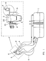
- la fig. 1 est une vue générale d'un réservoir à carburant pour véhicule automobile
- la fig. 2 est une vue en coupe d'un premier mode de réalisation d'un clapet de sécurité conforme à l'invention
- la fig. 3 est une vue en coupe d'un autre mode de réalisation d'un clapet de sécurité conforme à l'invention
- la fig. 4 est une vue en coupe d'un clapet de sécurité identique à celui de la fig. 3 dont le pointeau est équipé d'un clapet de surpression
- les fig. 5 à 9 montrent différents cas de fonctionnement d'un clapet de sécurité selon la fig. 3.
- fig. 1 is a general view of a fuel tank for a motor vehicle
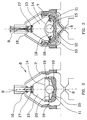
- fig. 2 is a sectional view of a first embodiment of a safety valve according to the invention
- fig. 3 is a sectional view of another embodiment of a safety valve according to the invention
- fig. 4 is a sectional view of a safety valve identical to that of FIG. 3 whose needle is fitted with a pressure relief valve
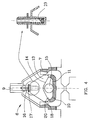
- fig. 5 to 9 show different cases of operation of a safety valve according to fig. 3.
Ainsi qu'il apparaît sur la fig. 1, le réservoir 1 d'un véhicule automobile comporte une canalisation de remplissage 2 pourvue d'une embouchure obturable 5, une canalisation de dégazage 3 raccordée à l'embouchure 5 et une canalisation de mise à l'air 4 dont une première partie est également raccordée à l'embouchure 5 et une seconde raccorde cette embouchure à l'atmosphère directement ou via un canister de récupération (non représenté). Dans la partie agrandie de la fig. 1, on montre le positionnement habituel du clapet de sécurité 6 conforme à l'invention (représenté schématiquement). Par ailleurs, sur cette partie agrandie, on remarque que la seconde partie de la canalisation de mise à l'air reprend non seulement les fluides s'écoulant dans la première partie mais encore les fluides s'écoulant par la canalisation de dégazage 3 et par la conduite de remplissage 2. Enfin, sur cette partie agrandie, on a représenté schématiquement un système à clapet 21 qui a pour fonction d'obturer la première partie de la canalisation de mise à l'air 4 lors de l'enlèvement du bouchon 22 en vue d'un remplissage du réservoir 1.As it appears in fig. 1, the
Ainsi qu'il apparaît plus particulièrement aux fig. 2 à 4, le clapet de sécurité conforme à l'invention comporte une enceinte externe 7 équipée, à sa base, d'un orifice d'entrée 8 et, à sa partie supérieure, d'un orifice de sortie 9. Dans cette enceinte est disposée une coupelle circulaire 10 fixe qui est maintenue espacée de la paroi interne de l'enceinte 7. Selon un premier mode de réalisation (fig. 2) la paroi interne 11 de la coupelle 10 est de profil conique et selon un second mode de réalisation (fig. 3) la paroi interne 11 de la coupelle est plan et pourvu en son centre d'une encoche sphérique 12.As appears more particularly in FIGS. 2 to 4, the safety valve according to the invention comprises an
L'enceinte 7 contient également un équipage déplaçable verticalement comprenant un flotteur 13 creux (fig. 2) ou réalisé en matière plastique cellulaire (fig. 3). En position normale, le flotteur repose sur le bord de la coupelle 10. Selon la première variante de réalisation la base 14 du flotteur 13 est plane (fig. 2) et selon la seconde variante (fig. 3) cette base 14 est profilée en forme de cone inversé. Une bille 15 de diamètre adéquat est disposée dans la coupelle 10. Dans le second mode de réalisation, l'encoche sphérique 12 a pour fonction de stabiliser la bille 15 au centre de la coupelle et d'empêcher un déplacement intempestif de cette bille sous l'effet d'une faible inclinaison de l'enceinte ou par inertie, par exemple lors d'une modification normale de la trajectoire du véhicule automobile.The
Le flotteur 13 est équipé à sa partie supérieure d'un pointeau 16 qui, en position haute du flotteur, obture l'orifice supérieur 9 de l'enceinte 7 par l'intermédiaire d'un joint membrane 17. Ainsi qu'il est représenté à la fig. 4 (partie agrandie), le pointeau peut éventuellement être équipé d'un clapet de surpression 23.The
En outre, il apparaît que l'espace annulaire entre la paroi interne de l'enceinte 7 et la coupelle 10 est profilé de façon à former un venturi 18. Ce venturi est maintenu en relation avec le volume 19 compris entre la coupelle 10 et la base du flotteur 13 par des passages constitués par des encoches 20 taillées dans le bord de la coupelle 10 et réparties le long de ce bord.In addition, it appears that the annular space between the internal wall of the
Ainsi qu'il apparaît plus particulièrement aux fig. 3 et 5 à 9, le clapet de sécurité selon l'invention permet à la canalisation de mise à l'air de remplir parfaitement ses fonctions et ferme cette canalisation de façon sure dans toute éventualité risquant d'entraîner une sortie non souhaitée de carburant liquide.As appears more particularly in FIGS. 3 and 5 to 9, the safety valve according to the invention allows the vent pipe to fulfill its functions perfectly and closes this pipe securely in any eventuality likely to cause an unwanted exit of liquid fuel .
Ainsi qu'il est montré aux fig. 3 et 6 , le clapet de sécurité permet, en situation normale, l'évacuation des vapeurs de carburant. Dans ce cas, la dépression créée dans le volume 19 contribue efficacement à maintenir le flotteur en position basse, nonobstant notamment sa légèreté, ce qui permet d'atteindre des débits d'évacuation très importants sans risque d'obturation de l'orifice 9.As shown in Figs. 3 and 6, the valve safety allows, in normal situation, the evacuation of fuel vapors. In this case, the depression created in the
En outre, ainsi qu'il apparaît à la fig. 5, en situation normale, le clapet permet une rentrée d'air dans le réservoir pour compenser le carburant consommé.Furthermore, as it appears in FIG. 5, in normal situation, the valve allows air to enter the tank to compensate for the fuel consumed.
Par contre, ainsi qu'il apparaît à la fig. 7, en cas d'une remontée du carburant liquide par la canalisation de mise à l'air, le carburant pénétrant dans l'enceinte entraîne le flotteur 13 vers le haut et partant une obturation sure de l'orifice de sortie 9.On the other hand, as it appears in FIG. 7, in the event of a rise in the liquid fuel via the venting pipe, the fuel entering the enclosure drives the
Enfin, en cas d'inclinaison anormale de l'enceinte, suite, par exemple, à un accident, la bille 15 se déplace par gravité dans la coupelle 10 et provoque également la montée du flotteur 13 et partant l'obturation sure de l'orifice de sortie 9.Finally, in the event of an abnormal inclination of the enclosure, following, for example, an accident, the
Claims (7)
- Safety valve, for a fuel-tank (1) vent pipe (4), which allows venting and prevents the passage of liquid fuel in any case and comprises a closed containment (7) equipped, in its lower part, with an inlet port (8) connected to the vent pipe (4) and, in its upper part, with an outlet port (9) likewise connected to the vent pipe, and in which :a) the lower part of the containment comprises a stationary circular inner cup (10) kept spaced from the inner wall of the containment (7) and from the lower inlet port (8), andb) the cup is surmounted by a vertically displaceable assembly comprising a float (13) of general frusto-conical or spherical shape and an upper needle (16) which is fixed to the float (13) and which, in the high position of the assembly, can close off the upper port of the containment, means being provided, for causing an upward displacement of the assembly as a result of an inclination of the containment, characterised in that the space between the inner wall of the containment and the cup is profiled so as to form a Venturi tube (18) which is kept in relationship via at least one passage (20) with the volume (19) located between the cup (10) and the float (13) of the assembly, in such a way that the passage of the fuel vapours into this space causes this volume to be put under a vacuum.
- Safety valve according to Claim 1, characterised in that the means for causing the upward displacement of the assembly as a result of an inclination of the containment consists of a ball (15) which is arranged in the cup (10) of conical inner profile, the lower part of the float (13) of the movable assembly being capable of bearing on this ball.
- Safety valve according to Claim 1, characterised in that the means for causing the upward displacement of the assembly as a result of an inclination of the containment consists of a ball (15) which is arranged in the cup (10) of plane inner profile equipped at its centre with a spherical indentation (12), the lower part of the float (13) of the assembly being capable of bearing on this ball and being profiled in the form of an inverted cone.
- Safety valve according to Claim 1, characterised in that the passage (20) consists of a space maintained between the edge of the cup (10) and the lower part of the hollow base of the assembly.
- Safety valve according to Claim 1, characterised in that the needle (16) is equipped with a diaphragm gasket (17) such that the maximum leakage from 0 to 10 kPa is 0.005 l/min.
- Safety valve according to Claim 1, characterised in that the needle (16) is equipped with a relief valve (23).
- Safety valve according to Claim 1, characterised in that the containment (7), the cup (10) and the assembly are produced from thermoplastic.
Applications Claiming Priority (2)
| Application Number | Priority Date | Filing Date | Title |
|---|---|---|---|
| FR9006016 | 1990-05-11 | ||
| FR9006016A FR2661969B1 (en) | 1990-05-11 | 1990-05-11 | SAFETY VALVE, PARTICULARLY FOR A VENTILATION PIPE OF A FUEL TANK. |
Publications (2)
| Publication Number | Publication Date |
|---|---|
| EP0456313A1 EP0456313A1 (en) | 1991-11-13 |
| EP0456313B1 true EP0456313B1 (en) | 1995-08-09 |
Family
ID=9396598
Family Applications (1)
| Application Number | Title | Priority Date | Filing Date |
|---|---|---|---|
| EP19910201055 Expired - Lifetime EP0456313B1 (en) | 1990-05-11 | 1991-05-03 | Safety valve, particularly for a ventilation conduit of a fuel tank |
Country Status (4)
| Country | Link |
|---|---|
| EP (1) | EP0456313B1 (en) |
| DE (1) | DE69111883T2 (en) |
| ES (1) | ES2078426T3 (en) |
| FR (1) | FR2661969B1 (en) |
Family Cites Families (3)
| Publication number | Priority date | Publication date | Assignee | Title |
|---|---|---|---|---|
| US3765435A (en) * | 1971-11-10 | 1973-10-16 | Gen Motors Corp | Tank vent control unit |
| FR2630686B1 (en) * | 1988-04-27 | 1991-07-12 | Peugeot | DEVICE FOR LIMITING THE FILLING OF A FUEL TANK AND MOTOR VEHICLE EQUIPPED WITH SUCH A DEVICE |
| US4917157A (en) * | 1989-02-27 | 1990-04-17 | General Motors Corporation | Vehicle tank vapor vent valve assembly |
-
1990
- 1990-05-11 FR FR9006016A patent/FR2661969B1/en not_active Expired - Fee Related
-
1991
- 1991-05-03 DE DE1991611883 patent/DE69111883T2/en not_active Expired - Fee Related
- 1991-05-03 EP EP19910201055 patent/EP0456313B1/en not_active Expired - Lifetime
- 1991-05-03 ES ES91201055T patent/ES2078426T3/en not_active Expired - Lifetime
Also Published As
| Publication number | Publication date |
|---|---|
| EP0456313A1 (en) | 1991-11-13 |
| FR2661969A1 (en) | 1991-11-15 |
| DE69111883D1 (en) | 1995-09-14 |
| ES2078426T3 (en) | 1995-12-16 |
| FR2661969B1 (en) | 1992-10-02 |
| DE69111883T2 (en) | 1996-05-02 |
Similar Documents
| Publication | Publication Date | Title |
|---|---|---|
| EP1539519B1 (en) | Guide for fuel filling nozzle with sealing and safety device | |
| EP1020670B1 (en) | Venting system for fluid reservoir | |
| FR2886367A1 (en) | VALVE FOR AIR FLOW CIRCUIT OF A LIQUID TANK | |
| EP1172306A1 (en) | Venting system for liquid tank | |
| FR2774951A1 (en) | Fuel tank with vent system assisting filling and preventing excess internal pressure | |
| FR2905442A1 (en) | VALVE FOR AIR FLOW CIRCUIT OF A LIQUID TANK | |
| EP0943476B1 (en) | Venting circuit for fluid reservoir | |
| EP0803671B1 (en) | Safety valve for a venting line in a liquid container | |
| EP0921026B1 (en) | Vapour venting circuit for liquid reservoir | |
| FR2886366A1 (en) | LIQUID TANK AIR SUPPLY SYSTEM | |
| US5247958A (en) | Safety valve, especially for a fuel tank vent pipe | |
| FR2954805A1 (en) | VALVE FOR AIR FLOW CIRCUIT OF A LIQUID TANK | |
| EP0456313B1 (en) | Safety valve, particularly for a ventilation conduit of a fuel tank | |
| EP1064166B1 (en) | Ventilating device for motor vehicle fuel tank | |
| FR2886368A1 (en) | SAFETY VALVE FOR AIR FLOW CIRCUIT OF A LIQUID TANK | |
| FR2858785A1 (en) | FUEL TANK WITH VALVE ASSEMBLY FOR REDUCING FUEL PERMEATION | |
| EP0774372B1 (en) | Improved venting device for fuel tank for motor vehicle and fuel tank including this device | |
| FR2905745A1 (en) | Fuel e.g. petrol, tank`s venting system for motor vehicle, has check valve forced in closed position of opening by float at level of fuel, where float straightens arm and support to stop deformation of valve when level attains certain limit | |
| EP0277869B1 (en) | Valve, particularly for venting motor car fuel tanks | |
| EP1064167B1 (en) | Ventilating device for motor vehicle fuel tank | |
| FR3069197A1 (en) | VENTILATION DEVICE FOR A VEHICLE LIQUID RESERVOIR | |
| FR2766134A1 (en) | Safety air inlet for vehicle fuel tank | |
| FR2559233A1 (en) | Automatic air vent for a pressurised-liquid pipe | |
| WO2016038259A1 (en) | Housing including a wall provided with a protective enclosure of a valve, and system including such a housing | |
| BE846103A (en) | AUTOMATIC GAS DRAIN |
Legal Events
| Date | Code | Title | Description |
|---|---|---|---|
| PUAI | Public reference made under article 153(3) epc to a published international application that has entered the european phase |
Free format text: ORIGINAL CODE: 0009012 |
|
| AK | Designated contracting states |
Kind code of ref document: A1 Designated state(s): BE DE ES GB IT NL SE |
|
| 17P | Request for examination filed |
Effective date: 19920422 |
|
| 17Q | First examination report despatched |
Effective date: 19931125 |
|
| GRAA | (expected) grant |
Free format text: ORIGINAL CODE: 0009210 |
|
| AK | Designated contracting states |
Kind code of ref document: B1 Designated state(s): BE DE ES GB IT NL SE |
|
| PG25 | Lapsed in a contracting state [announced via postgrant information from national office to epo] |
Ref country code: NL Free format text: LAPSE BECAUSE OF FAILURE TO SUBMIT A TRANSLATION OF THE DESCRIPTION OR TO PAY THE FEE WITHIN THE PRESCRIBED TIME-LIMIT Effective date: 19950809 |
|
| REF | Corresponds to: |
Ref document number: 69111883 Country of ref document: DE Date of ref document: 19950914 |
|
| ITF | It: translation for a ep patent filed | ||
| PG25 | Lapsed in a contracting state [announced via postgrant information from national office to epo] |
Ref country code: SE Effective date: 19951109 |
|
| REG | Reference to a national code |
Ref country code: ES Ref legal event code: FG2A Ref document number: 2078426 Country of ref document: ES Kind code of ref document: T3 |
|
| NLV1 | Nl: lapsed or annulled due to failure to fulfill the requirements of art. 29p and 29m of the patents act | ||
| GBT | Gb: translation of ep patent filed (gb section 77(6)(a)/1977) |
Effective date: 19951127 |
|
| PG25 | Lapsed in a contracting state [announced via postgrant information from national office to epo] |
Ref country code: BE Effective date: 19960531 |
|
| PLBE | No opposition filed within time limit |
Free format text: ORIGINAL CODE: 0009261 |
|
| STAA | Information on the status of an ep patent application or granted ep patent |
Free format text: STATUS: NO OPPOSITION FILED WITHIN TIME LIMIT |
|
| 26N | No opposition filed | ||
| BERE | Be: lapsed |
Owner name: SOC. DE TRANSFORMATION DES MATIERES PLASTIQUES S. Effective date: 19960531 |
|
| PGFP | Annual fee paid to national office [announced via postgrant information from national office to epo] |
Ref country code: ES Payment date: 20010530 Year of fee payment: 11 |
|
| REG | Reference to a national code |
Ref country code: GB Ref legal event code: IF02 |
|
| PG25 | Lapsed in a contracting state [announced via postgrant information from national office to epo] |
Ref country code: ES Free format text: LAPSE BECAUSE OF NON-PAYMENT OF DUE FEES Effective date: 20020504 |
|
| REG | Reference to a national code |
Ref country code: ES Ref legal event code: FD2A Effective date: 20030611 |
|
| PGFP | Annual fee paid to national office [announced via postgrant information from national office to epo] |
Ref country code: GB Payment date: 20040428 Year of fee payment: 14 |
|
| PG25 | Lapsed in a contracting state [announced via postgrant information from national office to epo] |
Ref country code: IT Free format text: LAPSE BECAUSE OF NON-PAYMENT OF DUE FEES Effective date: 20050503 Ref country code: GB Free format text: LAPSE BECAUSE OF NON-PAYMENT OF DUE FEES Effective date: 20050503 |
|
| GBPC | Gb: european patent ceased through non-payment of renewal fee |
Effective date: 20050503 |
|
| PGFP | Annual fee paid to national office [announced via postgrant information from national office to epo] |
Ref country code: DE Payment date: 20070426 Year of fee payment: 17 |
|
| PG25 | Lapsed in a contracting state [announced via postgrant information from national office to epo] |
Ref country code: DE Free format text: LAPSE BECAUSE OF NON-PAYMENT OF DUE FEES Effective date: 20081202 |