EP0976087B1 - Biometric recognition using a master pattern set - Google Patents
Biometric recognition using a master pattern set Download PDFInfo
- Publication number
- EP0976087B1 EP0976087B1 EP97922362A EP97922362A EP0976087B1 EP 0976087 B1 EP0976087 B1 EP 0976087B1 EP 97922362 A EP97922362 A EP 97922362A EP 97922362 A EP97922362 A EP 97922362A EP 0976087 B1 EP0976087 B1 EP 0976087B1
- Authority
- EP
- European Patent Office
- Prior art keywords
- interest
- master
- regions
- biometric
- pattern
- Prior art date
- Legal status (The legal status is an assumption and is not a legal conclusion. Google has not performed a legal analysis and makes no representation as to the accuracy of the status listed.)
- Expired - Lifetime
Links
Images


Classifications
-
- G—PHYSICS
- G06—COMPUTING; CALCULATING OR COUNTING
- G06V—IMAGE OR VIDEO RECOGNITION OR UNDERSTANDING
- G06V40/00—Recognition of biometric, human-related or animal-related patterns in image or video data
- G06V40/10—Human or animal bodies, e.g. vehicle occupants or pedestrians; Body parts, e.g. hands
- G06V40/12—Fingerprints or palmprints
- G06V40/1347—Preprocessing; Feature extraction
-
- G—PHYSICS
- G06—COMPUTING; CALCULATING OR COUNTING
- G06F—ELECTRIC DIGITAL DATA PROCESSING
- G06F18/00—Pattern recognition
Definitions
- the present invention generally relates to the field of image matching. More particularly, it relates to biometric, personal authentication systems that authenticate identities of individuals.
- the present invention can be applied generally in the field of image matching, the invention has particular utility in the area of personal identification.
- Identification of an individual or verifying whether an individual is the person he claims to be is a common problem faced by individuals, businesses, and governments. While sophisticated personal identification is often used for security in sensitive government and commercial installations, matching for personal identification has potential application wherever a person's identity needs to be identified or verified, such as in the control of access to physical locations, such as airports, industrial locations and in the home. It also has potential application in the control of access to computing and data management equipment and in banking or commercial transactions.
- Biometric indicia have also been used for personal identification. Biometrics is the study of biological phenomena, and in the area of personal identification, some chosen characteristic of a person is used to identify or verify that person's identity. Biometric identification is particularly useful because certain personal characteristics are substantially unique to each person and are difficult to reproduce by an impostor. Further, the recording and analysis of biometric data can be automated, thereby allowing use of computer controlled electronics and digital recording techniques.
- biometric indicia for identification purposes requires that a particular biometric factor is substantially unique for each individual, that it is readily measured and that it is invariant over the time period during which the person may be tested for identification. Further, the biometric indicia should be difficult to duplicate by an impostor in order to secure against erroneous identification.
- the biometric indicia may be biologically determined or it may be some characteristic that is learned or acquired, such as handwriting or voice patterns.
- Some of the biometric characteristics most investigated today for use in a personal identification system include fingerprints, hand or palm prints, retina scans, signatures and voice patterns.
- Hand or palm print techniques typically evaluate the shape of a person's hand or other significant features such as creases in the palm, but these techniques may be fooled by templates or models of the hand of an authorized person.
- Retina scanning techniques evaluate the pattern of blood vessels in a person's retina. A drawback of this technique is that the blood vessel pattern may vary over time, such as when alcohol is in the blood stream or during irregular use of glasses or contact lenses. Also, a user may feel uneasy about having his or her eye illuminated for retina scanning or the possibility of eye contamination if there is contact between the eye and the scanning apparatus.
- Signatures may be easily forged and must usually be evaluated by a human operator, although research has been done on automated systems that evaluate the dynamics of a person's handwriting, such as the speed and the force of hand movement and pauses in writing.
- voice patterns as the identifying characteristic encounters difficulties owing to the wide variations in a person's voice over time, the presence of background noise during an evaluation and the potential for an impostor to fool the system with a recording of the voice of an authorized person.
- fingerprints have been the most commonly used biometric characteristic for personal identification.
- the technology of personal identification through fingerprint analysis has long been used in law enforcement. This long term experience with fingerprint analysis has developed a large amount of information about fingerprints and has confirmed the uniqueness of a person's fingerprints.
- fingerprints have been recorded by inking the fingerprint and making a print on a card for storage. Particularly for applications outside of law enforcement, less burdensome and intrusive recording methods needed to be developed.
- the live fingerprint is read and the image is compared with a hologram of the fingerprint of the authorized person.
- This system requires the storage of a library of holograms at the testing location for each authorized person in the system and the use of a specialized light source and a complicated optics system.
- the live fingerprint typically is scanned and digitally recorded as a binary image of the fingerprint pattern.
- Characteristic features of the fingerprint pattern such as ridge endings, points of ridge bifurcation and the core of a whorl, each defining a feature of the fingerprint pattern, are found in the binary fingerprint image.
- the binary fingerprint image is compared with a stored master pattern that has been derived previously from a fingerprint of the authorized person in order to determine whether there is a match.
- Many systems that attempt to identify features in the fingerprint pattern such as forks or ridge endings must make decisions of matching early in the comparison process.
- the features of both the live and the master fingerprints are compared and a correlation function is applied to the comparison.
- a significant disadvantage of this type of system is that the user's finger typically is required to be in exact alignment with the image recording device so that the coordinate system of the binary image derived from the live fingerprint pattern is in the same orientation and position as the coordinate system of the master fingerprint pattern.
- human skin is elastic, how the skin of the finger interacts with the platen of the image recording device also can change the recorded live fingerprint. For example, elastic deformations or distortions of the recorded fingerprint due to the elastic nature of skin may be recorded, or oil on the skin may cause the platen to record wider ridges. Such variables often defeat the accuracy of systems that rely on correlation functions.
- EP-A-0 251 504 discloses the definition of most distinctive areas for the fingerprint of each user, together with the analysis and storage of their relative locations. These most distinctive areas are stored as a master pattern for the respective master print.
- a biometric recognition system involves two phases: creation of a master pattern set of authorized users biometric indicia and authentication using a classification neural network.
- To create the master pattern set an image of an authorized biometric user's indicia is divided into a plurality of regions of interest or "features". The system determines which features are the most useful for identification purposes. Master patterns are then created from these master features, thus creating a master pattern set.
- a sample pattern set of a user to be authenticated is similarly created.
- a neural network is used to compare the sample pattern set with the master pattern set to determine whether the user should be authenticated.
- the biometric recognition system of the present invention can be broken down into two phases.
- the first phase is creation of a set of master patterns, called the master pattern set, of an authorized user's biometric indicia.
- the second phase authentication, an image of the biometric indicia of a user to be authenticated, is obtained.
- Authentication requires a match between the user's presented live biometric pattern and a recorded master pattern set.
- a biometric recognition system for recognizing fingerprints will be described. However, those skilled in the art will readily recognize that with insubstantial changes, the embodiment described herein may be used to recognize other biometric indicia, such as facial features, pore prints or eye features.
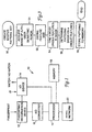
- FIG. 1 shows a block diagram of an embodiment of a fingerprint recognition system 10.
- Fingerprint recordation device acquires an image of the user's fingerprint. In conjunction with the acquired fingerprint image, information associated with the fingerprint image, such as the user's name and other data may be entered using input/output device 14 and stored to memory 18.
- a suitable fingerprint recordation device 12 must accept a user's thumb or finger, preferably in a generally predetermined orientation, and image the fingerprint.
- an image array of the fingerprint pattern may be a 512x512 pixel three color image having an integer number defining intensity with a definition range for each color of 0-255, a gray scale image having values for pixels between 0-255 or may be a binary image, each pixel defined with a single bit.
- a video image preprocessor module such as an analog-to-digital converter 15, will digitize the image information.
- Figure 2a and 2b show a semi-frontal view and a top plan view of a counter-mounted embodiment of the fingerprint recordation device 12 of the fingerprint recognition system 10 having an input/output device 14.
- Fingerprint recordation portion 12 has a thumb or finger positioning cavity 32, preferably with an indented platen, for receiving the thumb or finger comfortably and in a generally predetermined orientation. Finger positioning cavity 32 extends into the interior of the instrument providing access to detector window 30. The location and configuration of cavity 32 allows positioning of either the left or right hand of the individual seeking authentication.
- the configuration shown in Figure 2a is only one of many that would allow for positioning of the hands to adequately acquire a fingerprint pattern.
- detector window 30 could simply be a flat window integral in a counter or on a wall with placement guidelines thereon to ensure generally acceptable orientation.
- Fingerprint recordation device 12 images an individual's fingerprint with a CCD camera when the individual places a thumb or finger on detector window 30.
- Many cameras suitable for use are commercially available, such as Model FC-11 Fingerprint Capture Station, from Digital Biometrics, of Minnetonka MN. When the Digital Biometrics camera is used, then frame grabber IP-8 Image Processing Board commercially available from Matrox Electronic Systems, LTD, of Dorual, Quebec, Canada is also used.
- Model GPB1 from Sharp Electronics, Irvine CA, could be used in conjuction with Fingerprint Imager DFR-90 from Identicator, of San Bruno, CA which is a direct fingerprint reader with a CCD camera therein and which outputs a standard RS-170 video signal.
- processor 16 processes the digitized fingerprint image information according to the flow diagram illustrated in Figure 3. So that the acquired fingerprint image can be analyzed in detail, each fingerprint image acquired at block 51 is divided into a plurality of regions of interest.
- the regions of interest are overlapping, although the regions of interest may also be adjacent to each other.
- Each region of interest thus contains the information regarding a certain portion of the total fingerprint image.
- the regions of interest are referred to as "features”. It shall be understood therefore, that the terms “feature” and “regions of interest” may be used interchangeably for purposes of the present invention. However, for clarity and ease of understanding, the term “feature” shall be used throughout the detailed description.
- the feature size is defined at block 52.
- elastic deformations and distortions of the fingerprint pattern due to the elasticity of skin which can potentially cause recognition of an unauthorized user or failure to recognize the authorized user must be considered.
- the feature size must be defined such that a ridge in the fingerprint pattern will not move into a gap in the pattern.
- Figure 4 shows feature 70 of a fingerprint pattern having ridges 72 and gaps 74 between ridges 72.
- the size of feature 70 is selected such that ridge 72 will not deform due to elasticity into an area where gap 74 should be present.
- feature 70 is too large, a smaller number of pixels will represent the width of ridges 72 and gaps 74, thereby allowing a deformation of ridge 72 onto a gap 74. Further, the size of the feature is selected such that the elasticity of skin will not deform to a point where a ridge can stretch outside the boundaries of the feature.
- the maximum deformation measured in number of pixels must be significantly less than the number of pixels from the center of a ridge to the center of an adjacent gap measured across a diagonal of the feature.
- distance D represents the distance between the center of ridge 72 and gap 74 across diagonal 76.
- the feature size is chosen such that the maximum deformation measured in number of pixels will be significantly less than distance D.
- the size of a feature in number of pixels will vary, depending on the hardware chosen to implement the system, particularly with respect to the magnification of the optics. In a typical hardware implementation, where the resolution of the entire image is 256 x 256 pixels, a preferred feature size will have the dimensions of between 20-25 pixels square. Such a feature will typically contain approximately three to four ridges therein.
- angle ⁇ is defined by where the edges of ridge 72 intersect the boundaries of the feature 70.
- the size of feature 70 is preferably chosen such that angle ⁇ is significantly more than the angle that a user typically rotates. The smaller the feature size, the less problem with rotation.
- the n most unique features within the fingerprint image are identified at block 54.
- the system of the present invention identifies a predetermined number of unique features in the fingerprint.
- the features are preferably local as opposed to global structures. These "unique" features are then arranged with respect to each other in patterns, the pattern defining a global structure. These patterns are what is stored as the master pattern set.
- the features that are selected as being unique enough to characterize the fingerprint pattern could be selected in a number of different manners.
- the processor could compare features that originated from the same fingerprint pattern using a correlation function to determine the uniqueness of a feature with respect to other features within the same fingerprint.
- the processor could compare features with respect to features from a plurality of fingerprints, thereby determining the probability of a feature existing in any fingerprint.
- a preferred method of determining the n most unique features within a single fingerprint is shown in Figure 6.
- a feature is selected for determination of the feature's uniqueness within the fingerprint from which it was taken.
- the selected feature is compared with all other features in the image. From this comparison, each feature is assigned a uniqueness value at block 85.
- the feature comparison at block 82 preferably requires both uniqueness with respect to other features in the fingerprint and variance within the candidate feature.
- Uniqueness of a feature is the inverse of good correlation using a correlation function. A more unique feature will have a poor match or fit with other features in the same fingerprint.
- Variance within a feature requires that there is variance among the pixel values within the feature. For example, a feature having all black pixels or all gray pixels has little or no variance. Variance within a feature is desirable, as it can eliminate some features that have low correlation values but are not unique features.
- the system uses Equation I to determine the uniqueness, U, of each feature, R, within the image.
- Equation 1 S is the set of all m-by-m features in the image, with the exception of R, which is the reference feature.
- R ij is the (i, j)th pixel gray level in feature R.
- I ij is the (i, j)th pixel gray level in I.
- R and I are the mean gray levels within the respective features.
- the metric shown in Equation 1 requires both uniqueness of the feature within the image as well as variance within the feature.
- the system selects the n most unique features at block 88.
- the features with the n highest uniqueness values can be, but are not necessarily chosen when selecting the n most unique features. For example, in embodiments where the features overlap to a high degree, such as spaced by one pixel, several overlapping features which contain a very unique part of the fingerprint will have a high uniqueness value. In such a case, it is preferable to choose the feature with the highest uniqueness value in an area. After a feature has been selected, features occupying some area around the selected feature could be eliminated as candidates to be chosen as a unique feature.
- the image when selecting the n most unique features, the image may be analyzed in increments, such as in steps of one-third or one-half a feature, thereby ensuring that two selected features will overlap by at most one-third or one-half a feature size, respectively.
- Yet another embodiment can compare uniqueness values in an area and choose the feature with the maximum uniqueness value to represent that area.
- the number of features chosen, n may vary depending on a number of factors.
- the number of features chosen, n must be a large enough number such that the system is not too dependent on a particular individual feature when matching the live fingerprint pattern with the stored master pattern. If a pattern is too dependent on a single feature and not enough other features are used to define the pattern, then if a user presents a live fingerprint pattern with the feature translated off the image, then it can affect the accuracy of the match.
- too many features are chosen to define a pattern, then many features that are chosen might not provide significant data, because they are not that unique. When too many features are chosen, it further requires additional computation time from processor 16, which is undesirable if the additional features do not provide significant information.
- between four and twelve features are chosen to define a pattern. The number chosen depends on a number of factors, such as the speed of the processor or the resolution of the camera.
- n features are selected as the number of unique features that can define a fingerprint pattern, and p features in each pattern, then there are n ! / p !( n - p )! possible patterns.
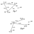
- Figure 7 shows how each pattern may be defined.
- a pattern is defined by a plurality of features and orientation data describing the location relationship of the features.
- a preferred format for defining a pattern is as a collection of p features along with the line lengths between each pair of features and the slopes of these lines.
- One of the three features is designated as the reference feature.
- feature P 1 102 is designated as the reference feature.
- the line length between the reference feature and the other two features is determined.
- length l 1 108 is the length between P 1 102 and P 2 104 and length l 2 110 is the length between P 1 102 and P 3 106.
- Pattern 100 is also defined by the slopes of lines 108 and 110, which are calculated by the angle of the lines relative to an arbitrary, predetermined reference.
- slopes ⁇ 1 and ⁇ 2 define the orientation of lines 108 and 110, respectively, with respect to a predetermined reference, such as a horizontal or vertical reference line.
- a predetermined reference such as a horizontal or vertical reference line.
- the reference feature, the line lengths between features and the line lengths' slopes can define the pattern.
- authentication will require that a live fingerprint pattern has both features that match the selected master features and that the features are oriented in the same pattern as the master pattern.
- One desirable property of a pattern is rotational invariance, meaning that if the live fingerprint is rotated with respect to the orientation of the master pattern image, the system can still match two similar patterns.
- the embodiment shown in Figure 7 is not rotationally invariant, it is rotationally tolerant because applying a correlation function still results in a high value for matching features as long as the rotation is significantly less than the angle ⁇ , as defined in Figure 5.
- One method of compensating for rotated live fingerprint patterns is storing patterns rotated in small increments, such as one degree or five degree increments, such that the most a user could realistically present a rotated live fingerprint pattern, based on the hardware, would be covered by the stored rotated patterns.
- the pattern may be defined by three lengths rather than two lengths and two angles. For example, in Figure 7, in addition to l 1 and l 2 , a third line length 112, the length between P 2 and P 3 , could define pattern 100. Defining pattern 100 in such a manner ensures that pattern 100 is rotationally invariant.
- Pattern 120 has four features, P 1 , P 2 , P 3 and P 4 defined by regions of interest 122, 124, 126 and 128, respectively. Each feature is defined by pixel location pairs (i, j), with feature P 1 designated as the reference feature. With four features, three line lengths l 1 , l 2 , and l 3 , representing the lengths between P 1 and P 2 , P 1 and P 3 and P 1 and P 4 , respectively, and three angles ⁇ 1 , ⁇ 2 , and ⁇ 3 , corresponding with line lengths l 1 , l 2 , and l 3 , define patterns 120.
- the length/angle format for storing patterns is preferred over other formats, such as length only, as it is easier to generalize with an arbitrarily large number of features in a pattern. It shall be understood however, that other means of representing orientation could be used without departing from the scope of the present invention.
- the format for storing the pattern preferably is not performed by storing pixel pair locations, as any translation of the live fingerprint would destroy any possible matching of all four feature locations. Expected locations of pixel pair locations, however, may be stored by the system for subsequent searching to expedite the matching process. Also, it is preferable to exclude features near the border of the image, as such features could be lost if the user translated the feature off the image acquiring device.
- the patterns are stored in memory at block 58.
- the system does not store the actual fingerprint image; rather, the patterns determined at block 56 and the features therein are stored as the master pattern set. For example, in an embodiment with six features and three features per pattern, pointers to the six features and the twenty patterns are stored in memory.
- the user is registered with the system.
- the above-described system allows the system itself to determine which features, or regions, of the fingerprint image are the most unique. These most unique features contain the most useful identifying information and are therefore the most useful for creation of the master pattern set.
- the system of the present invention determines which features are most unique or useful, the present system is more reliable than existing "minutae-based" systems which are restricted to certain predefined fingerprint features such as forks, dead ends, whorls, etc. In these types of systems, the features found and used by the system may not actually be the best identifying features. These initial feature decisions are then propagated through the system, resulting in a higher degree of false identifications or false rejects.
- the system of the present invention to decide for itself which features are the most unique, the system maintains the advantages of minutae based systems while increasing the reliability of the final result.
- the second phase of the present invention provides authentication of a user's biometric indicia. This requires that the system find a match between a presented live biometric indicia and one of the recorded master pattern sets of an authorized user. As mentioned above, the present invention will be described wherein the biometric indicia is a fingerprint.
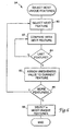
- Figure 9 shows a flow diagram of a preferred method of authenticating a presented live fingerprint with a recorded master pattern image stored in the format described above.
- the system preferably receives user identification information at block 150.
- This identification information can be, for example, a personal identification number (PIN), an id card or any other type of identification information.
- PIN personal identification number
- processor 16 retrieves the master pattern set corresponding to that user id information. Requiring the user to enter a PIN number is preferred, as it expedites the authentication process by providing information such as expected locations of features.
- the system could check each master pattern set stored in the system until a match is found, in which case the user would be authenticated, or, if no match is found, the user would not be authenticated.
- the system acquires an image of the user to be authenticated biometric indica, herein referred to as the sample image.
- processor 16 identifies the feature in the sample image that best matches each feature in the master pattern set. For example, in an embodiment where six features are used to define the master pattern set, the best match will be determined for each of the six features.
- a feature from the master pattern set is compared with some or all of the features from the sample image.
- the features in the sample image with which the master feature is compared may be overlapping regions, spaced by only one pixel, or may be spaced in increments of a plurality of pixels.
- the master feature can be compared with features within a subimage surrounding the expected location, such as a 40-by-40 or 80-by-80 pixel subimage.
- the features can be taken from the entire image.
- any of a number of well known functions may be employed.
- S is the set of all m-by-m features in the image or subimage.
- R is a feature from the master pattern image and is compared with each candidate feature, I, from the sample image.
- R ij is the (i, j)th pixel gray level in master feature R.
- I ij is the (i, j)th pixel gray level in sample feature I.
- R and I are the mean gray levels within the respective features.
- Each sample feature, I is in the search region S which is centered over the expected location of the feature.
- the expected location is the coordinate values of R in embodiments where an expected location is used.
- this set of matched sample features are used to generate a set of corresponding sample patterns at block 162.
- the master pattern set and the sample pattern set are then compared at block 164.
- the simplest method of pattern comparison is subtracting the line lengths and angles from the corresponding patterns from one another and using the correlation values, producing pattern difference vectors. For example, in an embodiment where each pattern consisted of three features, such a comparison would yield a seven dimensional difference function that defines the pattern difference:
- Each pattern difference vector generated at block 165 is then transmitted from processor 16 to neural network 20 to perform classification at block 166.
- Classification neural network 20 shown in Figure 1, is trained on a set of pattern difference vectors, some which are known to match and some which are known not to match. Neural network 20 classifies each of the received patterns as matching or not matching, producing classification designators indicating the classification and transmits the information back to processor 16.
- a preferred classification neural network is described in commonly-assigned U.S. Patent 6,167,390 to Brady et al., filed December 8, 1993 and entitled "Facet Classification Neural Network".
- processor 16 After processor 16 receives the classification designators from neural network 20, processor 16 determines whether the sample pattern image matches the master pattern image. At block 168 of Figure 9, processor 16 sums the number of classification designators indicating that patterns matched. This sum may be compared with a threshold value, ⁇ , and if the number of matching patterns exceed the threshold value, processor 16 determines that the fingerprints match.
- processor 16 could set the threshold based on frequency density functions.
- Figure 10 shows an example of frequency density functions 180 and 182 that processor 16 could use to set the threshold.
- Frequency density function 180 represents invalid comparisons while frequency density function 182 represents valid comparisons.
- On the x-axis is the number of matching patterns and on the y-axis is the number of comparisons,
- Frequency density functions 180 and 182 are a pair of histograms based on examples, indicated in Figure 10 by the discrete values at each number on the x-axis. A continuous function can be fit to the discrete values, as shown in Figures 10 and 11.
- Threshold value ⁇ is located where frequency density function 180 and 182 intersect, preferably where they are both at a minimum.
- the threshold value indicates the minimum number of patterns that must match for processor 16 to judge a match.
- Zero (0) matching patterns means that there is no match. In Figure 10, from one to seven matching patterns are also deemed that there is no match, although there is some error in the examples.
- processor 16 determines that the fingerprint patterns match and sends a match signal to input/output device 14 at block 170.
- Figure 11 shows another pair of histograms having crossover point 184 which do not intersect on the x-axis. In such a case, false authentications or false rejections may occur.
- the threshold value may be moved up or down the x-axis. For example, in a high security application where false authentications are not acceptable, a higher threshold value would be used, potentially causing some false rejects.
Applications Claiming Priority (3)
| Application Number | Priority Date | Filing Date | Title |
|---|---|---|---|
| US08/664,215 US5892838A (en) | 1996-06-11 | 1996-06-11 | Biometric recognition using a classification neural network |
| US664215 | 1996-06-11 | ||
| PCT/US1997/006583 WO1997048067A1 (en) | 1996-06-11 | 1997-04-21 | Biometric recognition using a classification neural network |
Publications (2)
| Publication Number | Publication Date |
|---|---|
| EP0976087A1 EP0976087A1 (en) | 2000-02-02 |
| EP0976087B1 true EP0976087B1 (en) | 2003-02-12 |
Family
ID=24665072
Family Applications (1)
| Application Number | Title | Priority Date | Filing Date |
|---|---|---|---|
| EP97922362A Expired - Lifetime EP0976087B1 (en) | 1996-06-11 | 1997-04-21 | Biometric recognition using a master pattern set |
Country Status (11)
| Country | Link |
|---|---|
| US (1) | US5892838A (ko) |
| EP (1) | EP0976087B1 (ko) |
| JP (1) | JP3975248B2 (ko) |
| KR (1) | KR100447023B1 (ko) |
| AR (1) | AR007516A1 (ko) |
| AU (1) | AU2805597A (ko) |
| BR (1) | BR9709670A (ko) |
| CA (1) | CA2256672C (ko) |
| DE (1) | DE69719085T2 (ko) |
| ES (1) | ES2189958T3 (ko) |
| WO (1) | WO1997048067A1 (ko) |
Families Citing this family (94)
| Publication number | Priority date | Publication date | Assignee | Title |
|---|---|---|---|---|
| US10361802B1 (en) | 1999-02-01 | 2019-07-23 | Blanding Hovenweep, Llc | Adaptive pattern recognition based control system and method |
| US6950810B2 (en) * | 1994-11-28 | 2005-09-27 | Indivos Corporation | Tokenless biometric electronic financial transactions via a third party identicator |
| US7613659B1 (en) * | 1994-11-28 | 2009-11-03 | Yt Acquisition Corporation | System and method for processing tokenless biometric electronic transmissions using an electronic rule module clearinghouse |
| US6192142B1 (en) * | 1994-11-28 | 2001-02-20 | Smarttouch, Inc. | Tokenless biometric electronic stored value transactions |
| US7882032B1 (en) | 1994-11-28 | 2011-02-01 | Open Invention Network, Llc | System and method for tokenless biometric authorization of electronic communications |
| US20040128249A1 (en) * | 1994-11-28 | 2004-07-01 | Indivos Corporation, A Delaware Corporation | System and method for tokenless biometric electronic scrip |
| US6397198B1 (en) * | 1994-11-28 | 2002-05-28 | Indivos Corporation | Tokenless biometric electronic transactions using an audio signature to identify the transaction processor |
| US7248719B2 (en) * | 1994-11-28 | 2007-07-24 | Indivos Corporation | Tokenless electronic transaction system |
| US5989835A (en) | 1997-02-27 | 1999-11-23 | Cellomics, Inc. | System for cell-based screening |
| EP0848347A1 (en) * | 1996-12-11 | 1998-06-17 | Sony Corporation | Method of extracting features characterising objects |
| US6105010A (en) * | 1997-05-09 | 2000-08-15 | Gte Service Corporation | Biometric certifying authorities |
| US6202151B1 (en) * | 1997-05-09 | 2001-03-13 | Gte Service Corporation | System and method for authenticating electronic transactions using biometric certificates |
| US6317544B1 (en) * | 1997-09-25 | 2001-11-13 | Raytheon Company | Distributed mobile biometric identification system with a centralized server and mobile workstations |
| US6408087B1 (en) * | 1998-01-13 | 2002-06-18 | Stmicroelectronics, Inc. | Capacitive semiconductor user input device |
| US6980670B1 (en) * | 1998-02-09 | 2005-12-27 | Indivos Corporation | Biometric tokenless electronic rewards system and method |
| WO2000007115A1 (en) * | 1998-07-30 | 2000-02-10 | Ethentica, Inc. | Method and system for controlling access to computer conferences using relief objects |
| JP4120997B2 (ja) * | 1998-10-23 | 2008-07-16 | 富士通株式会社 | 不正アクセス判断装置及び方法 |
| JP2002530748A (ja) * | 1998-11-13 | 2002-09-17 | セロミックス インコーポレイテッド | 実験データを効率的に収集して記憶するための方法及びシステム |
| US6631199B1 (en) * | 1998-12-08 | 2003-10-07 | Allen W. L. Topping | Automated identification through analysis of optical birefringence within nail beds |
| US6256737B1 (en) | 1999-03-09 | 2001-07-03 | Bionetrix Systems Corporation | System, method and computer program product for allowing access to enterprise resources using biometric devices |
| US7305562B1 (en) | 1999-03-09 | 2007-12-04 | Citibank, N.A. | System, method and computer program product for an authentication management infrastructure |
| US6324125B1 (en) * | 1999-03-30 | 2001-11-27 | Infineon Technologies Ag | Pulse width detection |
| DE19924628A1 (de) * | 1999-05-28 | 2000-11-30 | Giesecke & Devrient Gmbh | Einrichtung und Verfahren zur biometrischen Authentisierung |
| DE19935945A1 (de) * | 1999-07-30 | 2001-02-22 | Giesecke & Devrient Gmbh | Verfahren, Datenträger sowie System zur Authentisierung eines Benutzers und eines Endgeräts |
| US6490443B1 (en) | 1999-09-02 | 2002-12-03 | Automated Business Companies | Communication and proximity authorization systems |
| US6901155B2 (en) | 1999-12-23 | 2005-05-31 | National University Of Singapore | Wavelet-enhanced automated fingerprint identification system |
| AU2001229744A1 (en) | 2000-01-25 | 2001-08-07 | Cellomics, Inc. | Method and system for automated inference of physico-chemical interaction knowl edge |
| US7441263B1 (en) | 2000-03-23 | 2008-10-21 | Citibank, N.A. | System, method and computer program product for providing unified authentication services for online applications |
| JP4321944B2 (ja) * | 2000-04-27 | 2009-08-26 | 富士通株式会社 | 生体情報を用いた個人認証システム |
| US7318050B1 (en) * | 2000-05-08 | 2008-01-08 | Verizon Corporate Services Group Inc. | Biometric certifying authorities |
| US6496595B1 (en) | 2000-05-19 | 2002-12-17 | Nextgenid, Ltd. | Distributed biometric access control apparatus and method |
| US6504470B2 (en) | 2000-05-19 | 2003-01-07 | Nextgenid, Ltd. | Access control method and apparatus for members and guests |
| US9165323B1 (en) | 2000-05-31 | 2015-10-20 | Open Innovation Network, LLC | Biometric transaction system and method |
| AU2001266628A1 (en) | 2000-05-31 | 2001-12-11 | Indivos Corporation | Biometric financial transaction system and method |
| US7536557B2 (en) * | 2001-03-22 | 2009-05-19 | Ensign Holdings | Method for biometric authentication through layering biometric traits |
| US6813615B1 (en) | 2000-09-06 | 2004-11-02 | Cellomics, Inc. | Method and system for interpreting and validating experimental data with automated reasoning |
| US20020095608A1 (en) * | 2000-11-06 | 2002-07-18 | Slevin Richard S. | Access control apparatus and method for electronic device |
| US6961449B2 (en) * | 2001-01-16 | 2005-11-01 | University Of Massachusetts Lowell | Method of correlation of images in biometric applications |
| US7031502B1 (en) | 2001-01-29 | 2006-04-18 | University Of Massachusetts Lowell | Adjustable guide for viewing biometric surface patterns |
| US7181017B1 (en) | 2001-03-23 | 2007-02-20 | David Felsher | System and method for secure three-party communications |
| JP2002298141A (ja) | 2001-03-29 | 2002-10-11 | Nec Corp | パターン照合装置とそのパターン照合方法、及びパターン照合プログラム |
| US7398549B2 (en) * | 2001-05-18 | 2008-07-08 | Imprivata, Inc. | Biometric authentication with security against eavesdropping |
| FI20011370A (fi) * | 2001-06-27 | 2002-12-28 | Nokia Corp | Biotunnistusmenetelmä ja sitä hyödyntävä laite |
| US6758394B2 (en) * | 2001-07-09 | 2004-07-06 | Infonox On The Web | Identity verification and enrollment system for self-service devices |
| KR20050085583A (ko) * | 2002-12-13 | 2005-08-29 | 코닌클리케 필립스 일렉트로닉스 엔.브이. | 표정 불변 얼굴 인식 |
| US9818136B1 (en) | 2003-02-05 | 2017-11-14 | Steven M. Hoffberg | System and method for determining contingent relevance |
| US20040187029A1 (en) * | 2003-03-21 | 2004-09-23 | Ting David M. T. | System and method for data and request filtering |
| US7660880B2 (en) * | 2003-03-21 | 2010-02-09 | Imprivata, Inc. | System and method for automated login |
| US7580551B1 (en) * | 2003-06-30 | 2009-08-25 | The Research Foundation Of State University Of Ny | Method and apparatus for analyzing and/or comparing handwritten and/or biometric samples |
| CA2438220C (en) * | 2003-08-06 | 2011-11-08 | Click-Into Inc. | Identification of a person based on ultra-sound scan analyses of hand bone geometry |
| US7760918B2 (en) * | 2003-08-06 | 2010-07-20 | Zinayida Bezvershenko | Identification of a person based on ultra-sound scan analyses of hand bone geometry |
| JP4428067B2 (ja) * | 2004-01-28 | 2010-03-10 | ソニー株式会社 | 画像照合装置、プログラム、および画像照合方法 |
| JP2008502071A (ja) * | 2004-06-09 | 2008-01-24 | コーニンクレッカ フィリップス エレクトロニクス エヌ ヴィ | バイオメトリック・テンプレートの保護および特徴処理 |
| US20060034497A1 (en) * | 2004-08-15 | 2006-02-16 | Michael Manansala | Protometric authentication system |
| US20060104484A1 (en) * | 2004-11-16 | 2006-05-18 | Bolle Rudolf M | Fingerprint biometric machine representations based on triangles |
| US20060206722A1 (en) * | 2004-12-06 | 2006-09-14 | Zhang George Z | Method and apparatus for networked biometric authentication |
| US20060293891A1 (en) * | 2005-06-22 | 2006-12-28 | Jan Pathuel | Biometric control systems and associated methods of use |
| DE112006002388A5 (de) * | 2005-09-08 | 2008-06-05 | Grohmann Technologies Gmbh | Terminal und Verfahren zum Erfassen biometrischer Daten einer Person sowie Terminalsystem |
| US8874477B2 (en) | 2005-10-04 | 2014-10-28 | Steven Mark Hoffberg | Multifactorial optimization system and method |
| US20070244844A1 (en) * | 2006-03-23 | 2007-10-18 | Intelliscience Corporation | Methods and systems for data analysis and feature recognition |
| US8625885B2 (en) | 2006-03-23 | 2014-01-07 | Intelliscience Corporation | Methods and systems for data analysis and feature recognition |
| US7950021B2 (en) * | 2006-03-29 | 2011-05-24 | Imprivata, Inc. | Methods and systems for providing responses to software commands |
| ES2324896B1 (es) * | 2006-10-27 | 2010-05-24 | Universidad Del Pais Vasco-Euskal Herriko Unibertsitatea | Metodo de identificacion de muestras y sistema utilizado. |
| JP2008123207A (ja) * | 2006-11-10 | 2008-05-29 | Sony Corp | 登録装置、照合装置、登録方法、照合方法及びプログラム |
| IE20070437A1 (en) * | 2007-06-18 | 2009-02-18 | Nat Univ Ireland | Biometric print enrolment and authentication |
| US8031981B2 (en) * | 2007-12-21 | 2011-10-04 | Daon Holdings Limited | Method and systems for generating a subset of biometric representations |
| US8055470B2 (en) * | 2008-02-14 | 2011-11-08 | Yahoo!, Inc. | Simulated bucket testing |
| WO2009104429A1 (ja) * | 2008-02-19 | 2009-08-27 | 日本電気株式会社 | パターン照合装置、パターン照合方法、及びプログラム |
| US8175992B2 (en) | 2008-03-17 | 2012-05-08 | Intelliscience Corporation | Methods and systems for compound feature creation, processing, and identification in conjunction with a data analysis and feature recognition system wherein hit weights are summed |
| US8913831B2 (en) | 2008-07-31 | 2014-12-16 | Hewlett-Packard Development Company, L.P. | Perceptual segmentation of images |
| US8086745B2 (en) * | 2008-08-29 | 2011-12-27 | Fuji Xerox Co., Ltd | Graphical system and method for user authentication |
| JP2010286937A (ja) * | 2009-06-10 | 2010-12-24 | Hitachi Ltd | 生体認証方法、及び、生体認証に用いるクライアント端末、認証サーバ |
| JP5135384B2 (ja) * | 2010-06-02 | 2013-02-06 | 日立オムロンターミナルソリューションズ株式会社 | 生体認証サーバ、および生体認証システム |
| US20130170726A1 (en) * | 2010-09-24 | 2013-07-04 | The Research Foundation Of State University Of New York | Registration of scanned objects obtained from different orientations |
| US8461987B2 (en) * | 2010-11-17 | 2013-06-11 | Theodosios Kountotsis | System and method for performing chemical analysis of fingerprints for providing at least one response |
| US8724861B1 (en) * | 2010-12-06 | 2014-05-13 | University Of South Florida | Fingertip force, location, and orientation sensor |
| BR112013021059A2 (pt) * | 2011-02-16 | 2020-10-27 | Visa International Service Association | sistemas, métodos e aparelhos de pagamento móvel por snap |
| US10586227B2 (en) | 2011-02-16 | 2020-03-10 | Visa International Service Association | Snap mobile payment apparatuses, methods and systems |
| US10223691B2 (en) | 2011-02-22 | 2019-03-05 | Visa International Service Association | Universal electronic payment apparatuses, methods and systems |
| US9355393B2 (en) | 2011-08-18 | 2016-05-31 | Visa International Service Association | Multi-directional wallet connector apparatuses, methods and systems |
| US9582598B2 (en) | 2011-07-05 | 2017-02-28 | Visa International Service Association | Hybrid applications utilizing distributed models and views apparatuses, methods and systems |
| WO2013006725A2 (en) | 2011-07-05 | 2013-01-10 | Visa International Service Association | Electronic wallet checkout platform apparatuses, methods and systems |
| US9710807B2 (en) | 2011-08-18 | 2017-07-18 | Visa International Service Association | Third-party value added wallet features and interfaces apparatuses, methods and systems |
| US10825001B2 (en) | 2011-08-18 | 2020-11-03 | Visa International Service Association | Multi-directional wallet connector apparatuses, methods and systems |
| US10242358B2 (en) | 2011-08-18 | 2019-03-26 | Visa International Service Association | Remote decoupled application persistent state apparatuses, methods and systems |
| US10223730B2 (en) | 2011-09-23 | 2019-03-05 | Visa International Service Association | E-wallet store injection search apparatuses, methods and systems |
| AU2013214801B2 (en) | 2012-02-02 | 2018-06-21 | Visa International Service Association | Multi-source, multi-dimensional, cross-entity, multimedia database platform apparatuses, methods and systems |
| CN106796652A (zh) * | 2014-08-11 | 2017-05-31 | 辛纳普蒂克斯公司 | 多视图指纹匹配 |
| CN104751037B (zh) * | 2015-04-10 | 2018-06-12 | 无锡海斯凯尔医学技术有限公司 | 医疗检测设备的使用控制方法、系统和医疗检测设备 |
| RU2678494C1 (ru) * | 2017-08-24 | 2019-01-29 | Самсунг Электроникс Ко., Лтд. | Устройство и способ для биометрической идентификации пользователя с использованием рч (радиочастотного) радара |
| JP7165746B2 (ja) * | 2018-08-13 | 2022-11-04 | ベイジン・センスタイム・テクノロジー・デベロップメント・カンパニー・リミテッド | Id認証方法および装置、電子機器並びに記憶媒体 |
| CN110162957B (zh) * | 2018-09-11 | 2023-01-06 | 腾讯科技(深圳)有限公司 | 智能设备的鉴权方法和装置、存储介质、电子装置 |
| US10713544B2 (en) | 2018-09-14 | 2020-07-14 | International Business Machines Corporation | Identification and/or verification by a consensus network using sparse parametric representations of biometric images |
| CN112437926A (zh) | 2019-06-18 | 2021-03-02 | 神经技术Uab公司 | 使用前馈卷积神经网络的快速鲁棒摩擦脊印痕细节提取 |
Family Cites Families (17)
| Publication number | Priority date | Publication date | Assignee | Title |
|---|---|---|---|---|
| US4151512A (en) * | 1976-09-10 | 1979-04-24 | Rockwell International Corporation | Automatic pattern processing system |
| US5202929A (en) * | 1979-09-24 | 1993-04-13 | Lemelson Jerome H | Data system and method |
| NL8503290A (nl) * | 1985-11-27 | 1987-06-16 | Antoon Sibum | Werkwijze en inrichting voor het identificeren van personen. |
| US5067162A (en) * | 1986-06-30 | 1991-11-19 | Identix Incorporated | Method and apparatus for verifying identity using image correlation |
| US4857916A (en) * | 1987-02-26 | 1989-08-15 | Bellin Robert W | System and method for identifying an individual utilizing grasping pressures |
| US4896363A (en) * | 1987-05-28 | 1990-01-23 | Thumbscan, Inc. | Apparatus and method for matching image characteristics such as fingerprint minutiae |
| EP0308162A3 (en) * | 1987-09-15 | 1990-06-06 | Identix Incorporated | Optical system for fingerprint imaging |
| GB8900866D0 (en) * | 1989-01-16 | 1989-03-08 | Nat Res Dev | Biometrics |
| US4993068A (en) * | 1989-11-27 | 1991-02-12 | Motorola, Inc. | Unforgeable personal identification system |
| US5258924A (en) * | 1990-03-30 | 1993-11-02 | Unisys Corporation | Target recognition using quantization indexes |
| US5103486A (en) * | 1990-04-19 | 1992-04-07 | Grippi Victor J | Fingerprint/signature synthesis |
| US5161204A (en) * | 1990-06-04 | 1992-11-03 | Neuristics, Inc. | Apparatus for generating a feature matrix based on normalized out-class and in-class variation matrices |
| US5163094A (en) * | 1991-03-20 | 1992-11-10 | Francine J. Prokoski | Method for identifying individuals from analysis of elemental shapes derived from biosensor data |
| US5229764A (en) * | 1991-06-20 | 1993-07-20 | Matchett Noel D | Continuous biometric authentication matrix |
| US5291560A (en) * | 1991-07-15 | 1994-03-01 | Iri Scan Incorporated | Biometric personal identification system based on iris analysis |
| US5450504A (en) * | 1992-05-19 | 1995-09-12 | Calia; James | Method for finding a most likely matching of a target facial image in a data base of facial images |
| US5572597A (en) * | 1994-03-29 | 1996-11-05 | Loral Corporation | Fingerprint classification system |
-
1996
- 1996-06-11 US US08/664,215 patent/US5892838A/en not_active Expired - Fee Related
-
1997
- 1997-04-21 KR KR10-1998-0710035A patent/KR100447023B1/ko not_active IP Right Cessation
- 1997-04-21 ES ES97922362T patent/ES2189958T3/es not_active Expired - Lifetime
- 1997-04-21 JP JP50158098A patent/JP3975248B2/ja not_active Expired - Lifetime
- 1997-04-21 DE DE69719085T patent/DE69719085T2/de not_active Expired - Lifetime
- 1997-04-21 AU AU28055/97A patent/AU2805597A/en not_active Abandoned
- 1997-04-21 WO PCT/US1997/006583 patent/WO1997048067A1/en active IP Right Grant
- 1997-04-21 BR BR9709670-9A patent/BR9709670A/pt not_active Application Discontinuation
- 1997-04-21 EP EP97922362A patent/EP0976087B1/en not_active Expired - Lifetime
- 1997-04-21 CA CA002256672A patent/CA2256672C/en not_active Expired - Fee Related
- 1997-06-06 AR ARP970102470A patent/AR007516A1/es unknown
Also Published As
| Publication number | Publication date |
|---|---|
| KR100447023B1 (ko) | 2004-11-06 |
| ES2189958T3 (es) | 2003-07-16 |
| CA2256672A1 (en) | 1997-12-18 |
| WO1997048067A1 (en) | 1997-12-18 |
| DE69719085D1 (de) | 2003-03-20 |
| DE69719085T2 (de) | 2003-07-31 |
| CA2256672C (en) | 2006-06-20 |
| BR9709670A (pt) | 2000-05-09 |
| AU2805597A (en) | 1998-01-07 |
| AR007516A1 (es) | 1999-11-10 |
| KR20000016451A (ko) | 2000-03-25 |
| EP0976087A1 (en) | 2000-02-02 |
| JP2000512047A (ja) | 2000-09-12 |
| JP3975248B2 (ja) | 2007-09-12 |
| US5892838A (en) | 1999-04-06 |
Similar Documents
| Publication | Publication Date | Title |
|---|---|---|
| EP0976087B1 (en) | Biometric recognition using a master pattern set | |
| US4896363A (en) | Apparatus and method for matching image characteristics such as fingerprint minutiae | |
| US4805223A (en) | Skin-pattern recognition method and device | |
| Hong | Automatic personal identification using fingerprints | |
| Ribarić et al. | Multimodal biometric user-identification system for network-based applications | |
| EP1183638B1 (en) | Method and apparatus for creating a composite fingerprint image | |
| JPH09167231A (ja) | 生体測定による識別方法及びその装置 | |
| Ross | Information fusion in fingerprint authentication | |
| CA2273279A1 (en) | Biometric security encryption system | |
| Daramola et al. | Algorithm for fingerprint verification system | |
| EP0300167A2 (en) | Apparatus and method for matching image characteristics such as fingerprint minutiae | |
| Khokher et al. | Footprint identification: Review of an emerging biometric trait | |
| EP1162577A2 (en) | Biometric identification using pore prints | |
| GB2356961A (en) | Biometrics system | |
| Ribarić et al. | A biometric identification system based on the fusion of hand and palm features | |
| Ogundepo et al. | Development of a real time fingerprint authentication/identification system for students’ record | |
| Zayid et al. | Miniature and Orientation Map Feature Extraction | |
| Balaji et al. | Development of fusion biometric system for atm machines | |
| Li | Authenticating personal identities using palmprint recognition | |
| Tico et al. | A remote authentication system using fingerprints | |
| Afolabi et al. | Securing E-Library System with Bimodal Biometric | |
| Khuwaja et al. | Data acquisition and recognition of fingerprints with LVQ | |
| Rao | Efficient Approaches For Fingerprint And Palmprint Recognition | |
| Louro | Liveness Detection in Biometrics | |
| Oni | Identifiation and Biometrics Methods for Highly Secured Authentication |
Legal Events
| Date | Code | Title | Description |
|---|---|---|---|
| PUAI | Public reference made under article 153(3) epc to a published international application that has entered the european phase |
Free format text: ORIGINAL CODE: 0009012 |
|
| 17P | Request for examination filed |
Effective date: 19990107 |
|
| AK | Designated contracting states |
Kind code of ref document: A1 Designated state(s): DE ES FR GB IT NL |
|
| 17Q | First examination report despatched |
Effective date: 20010405 |
|
| GRAG | Despatch of communication of intention to grant |
Free format text: ORIGINAL CODE: EPIDOS AGRA |
|
| RTI1 | Title (correction) |
Free format text: BIOMETRIC RECOGNITION USING A MASTER PATTERN SET |
|
| GRAG | Despatch of communication of intention to grant |
Free format text: ORIGINAL CODE: EPIDOS AGRA |
|
| GRAG | Despatch of communication of intention to grant |
Free format text: ORIGINAL CODE: EPIDOS AGRA |
|
| GRAH | Despatch of communication of intention to grant a patent |
Free format text: ORIGINAL CODE: EPIDOS IGRA |
|
| GRAH | Despatch of communication of intention to grant a patent |
Free format text: ORIGINAL CODE: EPIDOS IGRA |
|
| GRAH | Despatch of communication of intention to grant a patent |
Free format text: ORIGINAL CODE: EPIDOS IGRA |
|
| GRAA | (expected) grant |
Free format text: ORIGINAL CODE: 0009210 |
|
| AK | Designated contracting states |
Designated state(s): DE ES FR GB IT NL |
|
| REG | Reference to a national code |
Ref country code: GB Ref legal event code: FG4D |
|
| REF | Corresponds to: |
Ref document number: 69719085 Country of ref document: DE Date of ref document: 20030320 Kind code of ref document: P |
|
| REG | Reference to a national code |
Ref country code: ES Ref legal event code: FG2A Ref document number: 2189958 Country of ref document: ES Kind code of ref document: T3 |
|
| ET | Fr: translation filed | ||
| PLBE | No opposition filed within time limit |
Free format text: ORIGINAL CODE: 0009261 |
|
| STAA | Information on the status of an ep patent application or granted ep patent |
Free format text: STATUS: NO OPPOSITION FILED WITHIN TIME LIMIT |
|
| 26N | No opposition filed |
Effective date: 20031113 |
|
| PGFP | Annual fee paid to national office [announced via postgrant information from national office to epo] |
Ref country code: NL Payment date: 20120413 Year of fee payment: 16 Ref country code: DE Payment date: 20120425 Year of fee payment: 16 |
|
| PGFP | Annual fee paid to national office [announced via postgrant information from national office to epo] |
Ref country code: GB Payment date: 20120418 Year of fee payment: 16 Ref country code: FR Payment date: 20120504 Year of fee payment: 16 |
|
| PGFP | Annual fee paid to national office [announced via postgrant information from national office to epo] |
Ref country code: IT Payment date: 20120420 Year of fee payment: 16 |
|
| PGFP | Annual fee paid to national office [announced via postgrant information from national office to epo] |
Ref country code: ES Payment date: 20120510 Year of fee payment: 16 |
|
| REG | Reference to a national code |
Ref country code: NL Ref legal event code: V1 Effective date: 20131101 |
|
| GBPC | Gb: european patent ceased through non-payment of renewal fee |
Effective date: 20130421 |
|
| PG25 | Lapsed in a contracting state [announced via postgrant information from national office to epo] |
Ref country code: GB Free format text: LAPSE BECAUSE OF NON-PAYMENT OF DUE FEES Effective date: 20130421 Ref country code: DE Free format text: LAPSE BECAUSE OF NON-PAYMENT OF DUE FEES Effective date: 20131101 |
|
| REG | Reference to a national code |
Ref country code: FR Ref legal event code: ST Effective date: 20131231 |
|
| PG25 | Lapsed in a contracting state [announced via postgrant information from national office to epo] |
Ref country code: IT Free format text: LAPSE BECAUSE OF NON-PAYMENT OF DUE FEES Effective date: 20130421 Ref country code: FR Free format text: LAPSE BECAUSE OF NON-PAYMENT OF DUE FEES Effective date: 20130430 Ref country code: NL Free format text: LAPSE BECAUSE OF NON-PAYMENT OF DUE FEES Effective date: 20131101 |
|
| REG | Reference to a national code |
Ref country code: DE Ref legal event code: R119 Ref document number: 69719085 Country of ref document: DE Effective date: 20131101 |
|
| REG | Reference to a national code |
Ref country code: ES Ref legal event code: FD2A Effective date: 20140610 |
|
| PG25 | Lapsed in a contracting state [announced via postgrant information from national office to epo] |
Ref country code: ES Free format text: LAPSE BECAUSE OF NON-PAYMENT OF DUE FEES Effective date: 20130422 |