EP0975813B1 - Verfahren zur herstellung von flüssigem roheisen oder flüssigen stahlvorprodukten - Google Patents
Verfahren zur herstellung von flüssigem roheisen oder flüssigen stahlvorprodukten Download PDFInfo
- Publication number
- EP0975813B1 EP0975813B1 EP98922677A EP98922677A EP0975813B1 EP 0975813 B1 EP0975813 B1 EP 0975813B1 EP 98922677 A EP98922677 A EP 98922677A EP 98922677 A EP98922677 A EP 98922677A EP 0975813 B1 EP0975813 B1 EP 0975813B1
- Authority
- EP
- European Patent Office
- Prior art keywords
- reduction
- sludges
- scrubber
- gas
- zone
- Prior art date
- Legal status (The legal status is an assumption and is not a legal conclusion. Google has not performed a legal analysis and makes no representation as to the accuracy of the status listed.)
- Expired - Lifetime
Links
- 238000000034 method Methods 0.000 title claims description 36
- 229910000805 Pig iron Inorganic materials 0.000 title claims description 8
- 239000007788 liquid Substances 0.000 title description 3
- 238000002360 preparation method Methods 0.000 title 1
- 239000007789 gas Substances 0.000 claims description 73
- XEEYBQQBJWHFJM-UHFFFAOYSA-N Iron Chemical compound [Fe] XEEYBQQBJWHFJM-UHFFFAOYSA-N 0.000 claims description 48
- 239000010802 sludge Substances 0.000 claims description 40
- 229910052742 iron Inorganic materials 0.000 claims description 22
- OKTJSMMVPCPJKN-UHFFFAOYSA-N Carbon Chemical compound [C] OKTJSMMVPCPJKN-UHFFFAOYSA-N 0.000 claims description 11
- 229910052799 carbon Inorganic materials 0.000 claims description 11
- 239000008187 granular material Substances 0.000 claims description 11
- 239000008188 pellet Substances 0.000 claims description 10
- 239000002184 metal Substances 0.000 claims description 7
- 229910052751 metal Inorganic materials 0.000 claims description 7
- 238000002156 mixing Methods 0.000 claims description 7
- 239000000126 substance Substances 0.000 claims description 7
- QVGXLLKOCUKJST-UHFFFAOYSA-N atomic oxygen Chemical compound [O] QVGXLLKOCUKJST-UHFFFAOYSA-N 0.000 claims description 6
- 239000000969 carrier Substances 0.000 claims description 6
- 229910052760 oxygen Inorganic materials 0.000 claims description 6
- 239000001301 oxygen Substances 0.000 claims description 6
- 239000002817 coal dust Substances 0.000 claims description 5
- 238000001035 drying Methods 0.000 claims description 5
- 239000000428 dust Substances 0.000 claims description 5
- 230000008030 elimination Effects 0.000 claims description 5
- 238000003379 elimination reaction Methods 0.000 claims description 5
- 229910000831 Steel Inorganic materials 0.000 claims description 4
- 239000010959 steel Substances 0.000 claims description 4
- 238000004519 manufacturing process Methods 0.000 claims description 3
- 239000002893 slag Substances 0.000 claims description 3
- 238000010924 continuous production Methods 0.000 claims description 2
- 238000005201 scrubbing Methods 0.000 claims 8
- 235000008733 Citrus aurantifolia Nutrition 0.000 claims 2
- 235000011941 Tilia x europaea Nutrition 0.000 claims 2
- 230000004907 flux Effects 0.000 claims 2
- 239000004571 lime Substances 0.000 claims 2
- 238000007599 discharging Methods 0.000 claims 1
- 238000006722 reduction reaction Methods 0.000 description 73
- 238000002844 melting Methods 0.000 description 22
- 230000008018 melting Effects 0.000 description 22
- 238000002309 gasification Methods 0.000 description 21
- ODINCKMPIJJUCX-UHFFFAOYSA-N Calcium oxide Chemical compound [Ca]=O ODINCKMPIJJUCX-UHFFFAOYSA-N 0.000 description 14
- UQSXHKLRYXJYBZ-UHFFFAOYSA-N iron oxide Inorganic materials [Fe]=O UQSXHKLRYXJYBZ-UHFFFAOYSA-N 0.000 description 11
- 238000005406 washing Methods 0.000 description 11
- 239000000292 calcium oxide Substances 0.000 description 7
- 235000012255 calcium oxide Nutrition 0.000 description 7
- 235000013980 iron oxide Nutrition 0.000 description 6
- 239000000047 product Substances 0.000 description 5
- 238000005054 agglomeration Methods 0.000 description 4
- 230000002776 aggregation Effects 0.000 description 4
- AXCZMVOFGPJBDE-UHFFFAOYSA-L calcium dihydroxide Chemical compound [OH-].[OH-].[Ca+2] AXCZMVOFGPJBDE-UHFFFAOYSA-L 0.000 description 4
- 239000000203 mixture Substances 0.000 description 4
- 238000003723 Smelting Methods 0.000 description 3
- 238000006243 chemical reaction Methods 0.000 description 3
- 238000004140 cleaning Methods 0.000 description 3
- 238000005469 granulation Methods 0.000 description 3
- 230000003179 granulation Effects 0.000 description 3
- 238000010438 heat treatment Methods 0.000 description 3
- 239000002562 thickening agent Substances 0.000 description 3
- 238000010744 Boudouard reaction Methods 0.000 description 2
- VYPSYNLAJGMNEJ-UHFFFAOYSA-N Silicium dioxide Chemical compound O=[Si]=O VYPSYNLAJGMNEJ-UHFFFAOYSA-N 0.000 description 2
- 230000015572 biosynthetic process Effects 0.000 description 2
- 239000000920 calcium hydroxide Substances 0.000 description 2
- 229910001861 calcium hydroxide Inorganic materials 0.000 description 2
- 238000001816 cooling Methods 0.000 description 2
- VBMVTYDPPZVILR-UHFFFAOYSA-N iron(2+);oxygen(2-) Chemical class [O-2].[Fe+2] VBMVTYDPPZVILR-UHFFFAOYSA-N 0.000 description 2
- 239000002245 particle Substances 0.000 description 2
- 239000007787 solid Substances 0.000 description 2
- 239000007858 starting material Substances 0.000 description 2
- XLYOFNOQVPJJNP-UHFFFAOYSA-N water Chemical compound O XLYOFNOQVPJJNP-UHFFFAOYSA-N 0.000 description 2
- 229910018072 Al 2 O 3 Inorganic materials 0.000 description 1
- 229910004298 SiO 2 Inorganic materials 0.000 description 1
- 238000005299 abrasion Methods 0.000 description 1
- 230000002411 adverse Effects 0.000 description 1
- PNEYBMLMFCGWSK-UHFFFAOYSA-N aluminium oxide Inorganic materials [O-2].[O-2].[O-2].[Al+3].[Al+3] PNEYBMLMFCGWSK-UHFFFAOYSA-N 0.000 description 1
- 239000011230 binding agent Substances 0.000 description 1
- 239000003575 carbonaceous material Substances 0.000 description 1
- 239000003638 chemical reducing agent Substances 0.000 description 1
- 239000010883 coal ash Substances 0.000 description 1
- 229910052681 coesite Inorganic materials 0.000 description 1
- 229910052593 corundum Inorganic materials 0.000 description 1
- 229910052906 cristobalite Inorganic materials 0.000 description 1
- 238000005265 energy consumption Methods 0.000 description 1
- 239000013067 intermediate product Substances 0.000 description 1
- YOBAEOGBNPPUQV-UHFFFAOYSA-N iron;trihydrate Chemical compound O.O.O.[Fe].[Fe] YOBAEOGBNPPUQV-UHFFFAOYSA-N 0.000 description 1
- 239000000463 material Substances 0.000 description 1
- 239000010814 metallic waste Substances 0.000 description 1
- 238000013021 overheating Methods 0.000 description 1
- 238000005453 pelletization Methods 0.000 description 1
- JTJMJGYZQZDUJJ-UHFFFAOYSA-N phencyclidine Chemical class C1CCCCN1C1(C=2C=CC=CC=2)CCCCC1 JTJMJGYZQZDUJJ-UHFFFAOYSA-N 0.000 description 1
- 239000002243 precursor Substances 0.000 description 1
- 238000004064 recycling Methods 0.000 description 1
- 238000010079 rubber tapping Methods 0.000 description 1
- 239000000377 silicon dioxide Substances 0.000 description 1
- 229910052682 stishovite Inorganic materials 0.000 description 1
- 239000013589 supplement Substances 0.000 description 1
- 229910052905 tridymite Inorganic materials 0.000 description 1
- 238000004148 unit process Methods 0.000 description 1
- 239000002699 waste material Substances 0.000 description 1
- 229910001845 yogo sapphire Inorganic materials 0.000 description 1
Images
Classifications
-
- C—CHEMISTRY; METALLURGY
- C21—METALLURGY OF IRON
- C21B—MANUFACTURE OF IRON OR STEEL
- C21B13/00—Making spongy iron or liquid steel, by direct processes
- C21B13/0006—Making spongy iron or liquid steel, by direct processes obtaining iron or steel in a molten state
- C21B13/0013—Making spongy iron or liquid steel, by direct processes obtaining iron or steel in a molten state introduction of iron oxide into a bath of molten iron containing a carbon reductant
- C21B13/002—Reduction of iron ores by passing through a heated column of carbon
-
- C—CHEMISTRY; METALLURGY
- C21—METALLURGY OF IRON
- C21B—MANUFACTURE OF IRON OR STEEL
- C21B13/00—Making spongy iron or liquid steel, by direct processes
- C21B13/14—Multi-stage processes processes carried out in different vessels or furnaces
-
- C—CHEMISTRY; METALLURGY
- C21—METALLURGY OF IRON
- C21B—MANUFACTURE OF IRON OR STEEL
- C21B2100/00—Handling of exhaust gases produced during the manufacture of iron or steel
- C21B2100/20—Increasing the gas reduction potential of recycled exhaust gases
- C21B2100/22—Increasing the gas reduction potential of recycled exhaust gases by reforming
-
- C—CHEMISTRY; METALLURGY
- C21—METALLURGY OF IRON
- C21B—MANUFACTURE OF IRON OR STEEL
- C21B2100/00—Handling of exhaust gases produced during the manufacture of iron or steel
- C21B2100/20—Increasing the gas reduction potential of recycled exhaust gases
- C21B2100/28—Increasing the gas reduction potential of recycled exhaust gases by separation
- C21B2100/282—Increasing the gas reduction potential of recycled exhaust gases by separation of carbon dioxide
-
- C—CHEMISTRY; METALLURGY
- C21—METALLURGY OF IRON
- C21B—MANUFACTURE OF IRON OR STEEL
- C21B2100/00—Handling of exhaust gases produced during the manufacture of iron or steel
- C21B2100/40—Gas purification of exhaust gases to be recirculated or used in other metallurgical processes
- C21B2100/44—Removing particles, e.g. by scrubbing, dedusting
-
- Y—GENERAL TAGGING OF NEW TECHNOLOGICAL DEVELOPMENTS; GENERAL TAGGING OF CROSS-SECTIONAL TECHNOLOGIES SPANNING OVER SEVERAL SECTIONS OF THE IPC; TECHNICAL SUBJECTS COVERED BY FORMER USPC CROSS-REFERENCE ART COLLECTIONS [XRACs] AND DIGESTS
- Y02—TECHNOLOGIES OR APPLICATIONS FOR MITIGATION OR ADAPTATION AGAINST CLIMATE CHANGE
- Y02P—CLIMATE CHANGE MITIGATION TECHNOLOGIES IN THE PRODUCTION OR PROCESSING OF GOODS
- Y02P10/00—Technologies related to metal processing
- Y02P10/10—Reduction of greenhouse gas [GHG] emissions
- Y02P10/122—Reduction of greenhouse gas [GHG] emissions by capturing or storing CO2
-
- Y—GENERAL TAGGING OF NEW TECHNOLOGICAL DEVELOPMENTS; GENERAL TAGGING OF CROSS-SECTIONAL TECHNOLOGIES SPANNING OVER SEVERAL SECTIONS OF THE IPC; TECHNICAL SUBJECTS COVERED BY FORMER USPC CROSS-REFERENCE ART COLLECTIONS [XRACs] AND DIGESTS
- Y02—TECHNOLOGIES OR APPLICATIONS FOR MITIGATION OR ADAPTATION AGAINST CLIMATE CHANGE
- Y02P—CLIMATE CHANGE MITIGATION TECHNOLOGIES IN THE PRODUCTION OR PROCESSING OF GOODS
- Y02P10/00—Technologies related to metal processing
- Y02P10/10—Reduction of greenhouse gas [GHG] emissions
- Y02P10/134—Reduction of greenhouse gas [GHG] emissions by avoiding CO2, e.g. using hydrogen
-
- Y—GENERAL TAGGING OF NEW TECHNOLOGICAL DEVELOPMENTS; GENERAL TAGGING OF CROSS-SECTIONAL TECHNOLOGIES SPANNING OVER SEVERAL SECTIONS OF THE IPC; TECHNICAL SUBJECTS COVERED BY FORMER USPC CROSS-REFERENCE ART COLLECTIONS [XRACs] AND DIGESTS
- Y02—TECHNOLOGIES OR APPLICATIONS FOR MITIGATION OR ADAPTATION AGAINST CLIMATE CHANGE
- Y02P—CLIMATE CHANGE MITIGATION TECHNOLOGIES IN THE PRODUCTION OR PROCESSING OF GOODS
- Y02P10/00—Technologies related to metal processing
- Y02P10/20—Recycling
-
- Y—GENERAL TAGGING OF NEW TECHNOLOGICAL DEVELOPMENTS; GENERAL TAGGING OF CROSS-SECTIONAL TECHNOLOGIES SPANNING OVER SEVERAL SECTIONS OF THE IPC; TECHNICAL SUBJECTS COVERED BY FORMER USPC CROSS-REFERENCE ART COLLECTIONS [XRACs] AND DIGESTS
- Y10—TECHNICAL SUBJECTS COVERED BY FORMER USPC
- Y10S—TECHNICAL SUBJECTS COVERED BY FORMER USPC CROSS-REFERENCE ART COLLECTIONS [XRACs] AND DIGESTS
- Y10S75/00—Specialized metallurgical processes, compositions for use therein, consolidated metal powder compositions, and loose metal particulate mixtures
- Y10S75/961—Treating flue dust to obtain metal other than by consolidation
Definitions
- the invention relates to a process for the production of molten pig iron or liquid steel precursors from starting materials formed from iron ore, preferably in bar and / or pellet form, and optionally aggregates, the starting materials being reduced directly to sponge iron in a reduction zone and the sponge iron being charged into a melting gasification zone and there it is melted with the supply of carbon carriers and oxygen-containing gas, a CO and H 2 -containing reducing gas being generated, withdrawn from the meltdown gasification zone and introduced into the reduction zone, where it is reacted and removed as top gas, and the top gas is subjected to a wash and the sludges separated in the process are at least partially agglomerated, and a plant for carrying out the process.
- a method of this type is known for example from AT-B - 376 241.
- Solid particles from the reducing gas and from the exiting from the reduction zone Top gas separated in cyclones and mixed with binders such as iron oxide dust, hot briquetted and fed to the meltdown gasification zone.
- binders such as iron oxide dust, hot briquetted and fed to the meltdown gasification zone.
- this solution is in view on the investment and operating costs.
- due to the introduction of Iron oxides are done in the smelting gasification zone to reduce the Reduce iron oxide, creating the meltdown gasification zone for the meltdown process required energy is withdrawn.
- the invention has for its object a method of the type described to develop further in such a way that it is possible in a simple and efficient manner to implement the resulting sludge completely and with the least possible energy consumption in to recirculate the process, with the introduction of the sludge into the Meltdown gasification zone associated disadvantages, i.e. one in the Melting gasification zone to perform increased reduction work as well as heat losses heating of the goods brought in should be avoided.
- This object is achieved in that the agglomerate (at least a subset of the sludges resulting from the washing of the top gas of the reduction zone was formed) in the reduction zone, preferably exclusively in the reduction zone, is recirculated.
- At least a subset of the Melting gasification zone emerging reducing gas also washed, the thereby resulting sludges are at least partially agglomerated and the so formed Agglomerate recirculated into the reduction zone.
- the cleaned top gas from the reduction zone is subjected to a CO 2 elimination after washing and is fed as at least largely CO 2 -free reducing gas to at least one further reduction zone for the direct reduction of metal ore, in particular iron ore or pellets, after reaction with the metal ore in the withdrawn another reduction zone as export gas and cleaned in a scrubber, and the sludges obtained when washing the export gas from the further reduction zone are at least partially agglomerated, and the agglomerate thus formed is recirculated into the first reduction zone.
- the sludge to be agglomerated The inventive method first dewatered to a residual moisture content.
- oxidic dusts possibly coal dust and quicklime added.
- the method according to the invention become oxidic dusts from the foundry dedusting of a metallurgical plant, in particular from a plant for carrying out the method or from the dedusting plant Electric furnace of the melting gasification zone and / or further reduction zone downstream steelworks used.
- the agglomerates or granules are expediently recirculated into the Reduction zone dried.
- a plant for the production of molten pig iron or molten steel intermediate products of iron ore, preferably in piece and / or pellet form, and, if necessary, aggregates formed feedstocks, with a reduction reactor for iron ore, a Melting gasifier, one connecting the melting gasifier with the reduction reactor Supply line for a reducing gas formed in the melter, the one Reduction reactor with the melter connecting feed line for the in Reduction reactor formed reduction product, with one from the reduction reactor outgoing, with a scrubber top gas discharge, with in the melter gasifier opening supply lines for carbon carriers and oxygen-containing gases and one racking for pig iron and slag provided on the smelting gasifier and with one the scrubber to a device for agglomerating at least a part of the in Sludge discharge resulting from sludge is characterized by that the device for agglomerating the sludge line with the Reduction reactor is connected.
- the outlet into the reduction reactor Reduction gas supply line a second scrubber for at least a portion of the Reducing gas is provided, from which a sludge discharge to a device for Agglomeration of at least a part of the sludge produced in the second scrubber leads which device is connected by line to the reduction reactor.
- the sludge discharge associated with the second scrubber is also advantageous in terms of line the sludge discharge associated with the first scrubber.
- a further reduction reactor for receiving metal ore, in particular further iron ore or pellets, with a reduction gas feed line, with an export gas discharge line provided with a third scrubber and with a discharge device for the reduction product formed in this reduction reactor is provided, the top gas Discharge of the first reduction reactor opens into a CO 2 elimination system, from which the reducing gas feed line of the further reduction reactor starts and opens into the further reduction reactor, and wherein a sludge discharge from the third scrubber leads to a device for agglomerating at least a portion of those in the third scrubber Sludge leads which device is connected by line to the first reduction reactor.
- the one assigned to the first, second and / or third scrubber preferably leads Sludge discharge before the sludge agglomerating unit into one Sludge dewatering device, which is expediently designed as a decanter centrifuge.
- the device for agglomerating the sludge is expedient as a two-stage mixing and pelletizer and formed according to a preferred embodiment a drying device is connected to the first reduction reactor in terms of line.
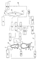
- a reduction reactor designed as a shaft furnace 1, i.e. in its fixed bed reduction zone 2, are 3-piece iron oxide containing from above via a feed line Feedstocks 4, such as ore, optionally together with unfired aggregates 5, are charged.
- the shaft furnace 1 is connected to a melter gasifier 6 in which Carbon carriers and oxygen-containing gas, a reducing gas is generated, which over a feed line 7 is fed to the shaft furnace 1 and this in counterflow to the Flow materials 4.
- a gas cleaning and Gas cooling device 8 which is designed as a scrubber, provided by the at least a partial stream of the reducing gas is passed through for the purpose of temperature adjustment.
- the melter gasifier 6 has a feed line 9 for solid, lumpy carbon carriers 10 and Supply lines 11 for oxygen-containing gases. In the melter gasifier 6 collects below the melting gasification zone 12 molten pig iron 13 and molten slag 14, which is tapped separately, each with its own tapping 15, 16 become.
- the resulting in the washer 19 sludge together with the sludge in the Scrubbers 8 are produced when washing the reduction gas fed to the shaft furnace 1, fed to a thickener 20.
- the thickened sludge from the thickener 20 a conveying line 21 of a sludge drying device 22, e.g. a decanter centrifuge, fed.
- the dewatered sludges are treated with dry oxidic dusts 23, such as ore abrasion and Foundry dust. and coal dust 24 mixed.
- This mixture of sludges and Dusts are then fed to a mixing and granulating device 25a, 25b, in which to further reduce the residual moisture in the dewatered sludge of quicklime 26 is added.
- the mixing and granulating device 25a, 25b granulates the Mixture of sludges, dusts 23, 24 and quicklime 26 to form a granulate two-stage.
- the Process steps mixing and granulation in separate reactors which have different sizes, are equipped with separate drives and on the Tasks mixing on the one hand and granulating on the other hand coordinated mixing and Have pelletizing tools.
- the granules are fed to a drying device 28 via a conveyor line 27 and then via the feed line 3 for the lumpy feedstocks containing iron oxide 4 and Supplements 5 introduced in the shaft furnace 1.
- the granules are dried preferably continuously in a third aggregate after granulation.
- This The unit can be designed with a heatable double jacket.
- the top gas cleaned in the scrubber 19 is subjected to CO 2 elimination, for example in a CO 2 scrubber 29 or a reformer, and is then a reducing gas Another reduction reactor 30 for receiving metal ore - in the illustrated embodiment for receiving iron ore or pellets 31 - available. If necessary, this reducing gas is subjected to heating before it is introduced into the further reduction reactor, but this is not shown in the exemplary embodiment.
- the further reduction reactor 30 is also designed as a shaft furnace and works like the first shaft furnace 1 in the counterflow principle.
- Iron ore in piece and / or pellet form also in a fixed bed reduction zone 32 Directly reduced sponge iron.
- the ore feed line is 33 and the sponge iron discharge device designated with 34.
- the export gas drawn off from the second reduction reactor 30 via the line 35 becomes also subjected to cleaning and cooling in an export gas scrubber 36 to remove it from To clean dust particles and lower the water vapor content, whereupon one can be used for further use.
- the sludges produced in the export gas scrubber 36 are thickened in a thickener 37 and fed via a line 38 to the delivery line 21.
- the invention is not limited to that shown in the drawing Embodiment, but also includes other embodiments.
- the sludge deposited in the washers 8, 19 and 36 can be separated separately separate delivery lines of the reduction zone 2 are supplied, if necessary after dewatering in separate sludge dewatering facilities or after agglomeration in separate agglomeration facilities. This way the chemical in their Composition, if necessary, different sludges before introduction into the Reduction zone 2 are treated specifically.
Landscapes
- Engineering & Computer Science (AREA)
- Chemical & Material Sciences (AREA)
- Manufacturing & Machinery (AREA)
- Materials Engineering (AREA)
- Metallurgy (AREA)
- Organic Chemistry (AREA)
- Manufacture And Refinement Of Metals (AREA)
- Manufacture Of Iron (AREA)
Description
- Eisen und Eisenoxide
- Kalziumhydroxid
- Kohlenstoff
- Kohlenaschebestandteile wie Al2O3, SiO2, etc.
- Durch den Gehalt an Kohlenstoff in den Granulaten wird die Boudouard-Reaktion, C + CO2 → 2 CO, welche wärmeverbrauchend abläuft, gefördert.
- Der Gehalt an Kalziumhydroxid, welches aus zugesetztem CaO gebildet wird, löst eine weitere wärmeverbrauchende Reaktion aus (Rückbildung von CaO).
Claims (20)
- Verfahren zur Herstellung von flüssigem Roheisen (13) oder flüssigen Stahlvorprodukten aus von Eisenerz (4), vorzugsweise in Stück- und/oder Pelletform, und gegebenenfalls Zuschlägen (5) gebildeten Einsatzstoffen, wobei die Einsatzstoffe in einer Reduktionszone (2) zu Eisenschwamm direkt reduziert werden, der Eisenschwamm in eine Einschmelzvergasungszone (12) chargiert und dort unter Zufuhr von Kohlenstoffträgem (10) und sauerstoffhältigem Gas erschmolzen wird, wobei ein CO- und H2-hältiges Reduktionsgas erzeugt, aus der Einschmelzvergasungszone (12) abgezogen und in die Reduktionszone (2) eingeleitet, dort umgesetzt und als Topgas abgezogen wird, und wobei das Topgas einer Wäsche unterzogen wird und die dabei abgeschiedenen Schlämme zumindest teilweise agglomeriert werden, dadurch gekennzeichnet, daß das so gebildete Agglomerat in die Reduktionszone (2), vorzugsweise ausschließlich in die Reduktionszone (2), rezirkuliert wird.
- Verfahren nach Anspruch 1, dadurch gekennzeichnet, daß zumindest eine Teilmenge des aus der Einschmelzvergasungszone (12) austretenden Reduktionsgases gewaschen wird, die dabei anfallenden Schlämme zumindest teilweise agglomeriert werden und das so gebildete Agglomerat in die Reduktionszone (2) rezirkuliert wird.
- Verfahren nach Anspruch 2, dadurch gekennzeichnet, daß die beim Waschen des Reduktionsgases aus der Einschmelzvergasungszone (2) anfallenden, zu agglomerierenden Schlämme gemeinsam mit den beim Waschen des Topgases aus der Reduktionszone (2) anfallenden, zu agglomerierenden Schlämmen weiterbehandelt werden.
- Verfahren nach einem der Ansprüche 1 bis 3, dadurch gekennzeichnet, daß das gereinigte Topgas aus der Reduktionszone (2) nach dem Waschen einer CO2-Eliminierung unterzogen wird und als zumindest weitgehend CO2-freies Reduktionsgas mindestens einer weiteren Reduktionszone (32) zur Direktreduktion von Metallerz, insbesondere von Eisenerz oder Pellets (31), zugeführt wird, nach Umsetzung mit dem Metallerz in der weiteren Reduktionszone (32) als Exportgas abgezogen und in einem Wäscher (36) gereinigt wird und daß die beim Waschen des Exportgases aus der weiteren Reduktionszone (32) anfallenden Schlämme zumindest teilweise agglomeriert werden und das so gebildete Agglomerat in die erste Reduktionszone (2) rezirkuliert wird.
- Verfahren nach Anspruch 4, dadurch gekennzeichnet, daß die beim Waschen des Exportgases aus der weiteren Reduktionszone (32) anfallenden, zu agglomerierenden Schlämme gemeinsam mit den beim Waschen des Topgases aus der ersten Reduktionszone (2) anfallenden und/oder gemeinsam mit den beim Waschen des Reduktionsgases aus der Einschmelzvergasungszone (12) anfallenden, zu agglomerierenden Schlämmen weiterbehandelt werden.
- Verfahren nach einem der Ansprüche 1 bis 5, dadurch gekennzeichnet, daß die zu agglomerierenden Schlämme zunächst auf einen Restfeuchtegehalt entwässert werden.
- Verfahren nach einem der Ansprüche 1 bis 6, dadurch gekennzeichnet, daß den zu agglomerierenden Schlämmen oxidische Stäube (23), gegebenenfalls Kohlestaub (24) und Branntkalk (26) zugesetzt werden.
- Verfahren nach einem der Ansprüche 1 bis 7, dadurch gekennzeichnet, daß die zu agglomerierenden Schlämme in einem zweistufigen kontinuierlichen Verfahren mit oxidischen Stäuben (23), gegebenenfalls Kohlestaub (24) und Branntkalk (26) gemischt und anschließend granuliert werden.
- Verfahren nach Anspruch 7 oder 8, dadurch gekennzeichnet, daß oxidische Stäube aus der Gießhallenentstaubung eines Hüttenwerkes eingesetzt werden.
- Verfahren nach Anspruch 7 oder 8, dadurch gekennzeichnet, daß oxidische Stäube aus einer Anlage zur Durchführung des Verfahrens gemäß einem der Ansprüche 1 bis 8 bzw. aus der Entstaubungsanlage eines Elektroofens eines der Einschmelzvergasungszone (12) und/oder der weiteren Reduktionszone (32) nachgeschalteten Stahlwerks, eingesetzt werden.
- Verfahren nach einem der Ansprüche 1 bis 10, dadurch gekennzeichnet, daß die Agglomerate bzw. Granulate vor dem Rezirkulieren in die Reduktionszone (2) getrocknet werden.
- Anlage zur Herstellung von flüssigem Roheisen (13) oder flüssigen Stahlvorprodukten aus von Eisenerz (4), vorzugsweise in Stück- und/oder Pelletform, und gegebenenfalls Zuschlägen (5) gebildeten Einsatzstoffen, mit einem Reduktionsreaktor (1) für Eisenerz, einem Einschmelzvergaser (6), einer den Einschmelzvergaser (6) mit dem Reduktionsreaktor (1) verbindenden Zuleitung (7) für ein im Einschmelzvergaser (6) gebildetes Reduktionsgas, einer den Reduktionsreaktor (1) mit dem Einschmelzvergaser (6) verbindenden Förderleitung (17) für das im Reduktionsreaktor (1) gebildete Reduktionsprodukt, mit einer vom Reduktionsreaktor (1) ausgehenden, mit einem Wäscher (19) versehenen Topgas-Ableitung (18), mit in den Einschmelzvergaser (6) mündenden Zuleitungen (9,11) für Kohlenstoffträger (10) und sauerstoffhältige Gase und einem am Einschmelzvergaser (6) vorgesehenen Abstich (15,16) für Roheisen (13) und Schlacke (14) und mit einer aus dem Wäscher (19) zu einer Einrichtung (25a, 25b) zum Agglomerieren von zumindest einem Teil der im Wäscher (19) anfallenden Schlämme führenden Schlammableitung (21), dadurch gekennzeichnet, daß die Einrichtung (25a, 25b) zum Agglomerieren der Schlämme leitungsmäßig mit dem Reduktionsreaktor (1) verbunden ist.
- Anlage nach Anspruch 12, dadurch gekennzeichnet, daß in der in den Reduktionsreaktor (1) mündenden Reduktionsgas-Zuleitung (7) ein zweiter Wäscher (8) für zumindest eine Teilmenge des Reduktionsgases vorgesehen ist, von dem eine Schlammableitung zu einer Einrichtung zum Agglomerieren (25a, 25b) von zumindest einem Teil der im zweiten Wäscher (8) anfallenden Schlämme führt, welche Einrichtung (25a, 25b) leitungsmäßig mit dem Reduktionsreaktor (1) verbunden ist.
- Anlage nach Anspruch 13, dadurch gekennzeichnet, daß die dem zweiten Wäscher (8) zugeordnete Schlammableitung leitungsmäßig mit der dem ersten Wäscher (19) zugeordneten Schlammableitung (21) verbunden ist.
- Anlage nach einem der Ansprüche 12 bis 14, dadurch gekennzeichnet, daß mindestens ein weiterer Reduktionsreaktor (30) zur Aufnahme von Metallerz, insbesondere von weiterem Eisenerz oder Pellets (31), mit einer Reduktionsgas-Zuleitung, mit einer mit einem dritten Wäscher (36) versehenen Exportgas-Ableitung (35) und mit einer Austragsvorrichtung (34) für das in diesem Reduktionsreaktor (30) gebildete Reduktionsprodukt vorgesehen ist, wobei die Topgas-Ableitung (18) des ersten Reduktionsreaktors in eine CO2-Eliminierungsanlage (29) mündet, von der die Reduktionsgas-Zuleitung des weiteren Reduktionsreaktors (30) ausgeht und in den weiteren Reduktionsreaktor (30) mündet und wobei eine Schlammableitung (38) aus dem dritten Wäscher (36) zu einer Einrichtung (25a, 25b) zum Agglomerieren von zumindest einem Teil der im dritten Wäscher (36) anfallenden Schlämme führt, welche Einrichtung (25a, 25b) leitungsmäßig mit dem ersten Reduktionsreaktor (1) verbunden ist.
- Anlage nach Anspruch 15, dadurch gekennzeichnet, daß die dem dritten Wäscher (36) zugeordnete Schlammableitung (38) leitungsmäßig mit der dem ersten und/oder zweiten Wäscher (19, 8) zugeordneten Schlammableitung (21) verbunden ist.
- Anlage nach einem der Ansprüche 12 bis 16, dadurch gekennzeichnet, daß die dem ersten, zweiten und/oder dritten Wäscher zugeordnete(n) Schlammableitung(en) (21, 38) vor der (den) Einrichtung(en) (25a, 25b) zum Agglomerieren der Schlämme zu (einer) Schlammentwässerungseinrichtung(en) (22) führt (führen).
- Anlage nach Anspruch 17, dadurch gekennzeichnet, daß die Schlammentwässerungseinrichtung(en) (22) als Dekanterzentrifuge(n) ausgebildet ist (sind).
- Anlage nach einem der Ansprüche 12 bis 18, dadurch gekennzeichnet, daß die Einrichtung(en) (25a, 25b) zum Agglomerieren der Schlämme als zweistufige Misch- und Granuliereinrichtung(en) ausgebildet ist (sind).
- Anlage nach einem der Ansprüche 12 bis 19, dadurch gekennzeichnet, daß die Einrichtung(en) (25a, 25b) zum Agglomerieren der Schlämme über (eine) Trocknungseinrichtung(en) (28) mit dem ersten Reduktionsreaktor (1) leitungsmäßig verbunden ist (sind).
Applications Claiming Priority (3)
| Application Number | Priority Date | Filing Date | Title |
|---|---|---|---|
| AT65997 | 1997-04-16 | ||
| AT97659A AT404598B (de) | 1997-04-16 | 1997-04-16 | Verfahren und anlage zur herstellung von fluessigem roheisen oder fluessigen stahlvorprodukten |
| PCT/EP1998/002086 WO1998046800A1 (de) | 1997-04-16 | 1998-04-09 | Verfahren zur herstellung von flüssigem roheisen oder flüssigen stahlvorprodukten |
Publications (2)
| Publication Number | Publication Date |
|---|---|
| EP0975813A1 EP0975813A1 (de) | 2000-02-02 |
| EP0975813B1 true EP0975813B1 (de) | 2001-10-17 |
Family
ID=3496442
Family Applications (1)
| Application Number | Title | Priority Date | Filing Date |
|---|---|---|---|
| EP98922677A Expired - Lifetime EP0975813B1 (de) | 1997-04-16 | 1998-04-09 | Verfahren zur herstellung von flüssigem roheisen oder flüssigen stahlvorprodukten |
Country Status (14)
| Country | Link |
|---|---|
| US (1) | US6293991B1 (de) |
| EP (1) | EP0975813B1 (de) |
| JP (1) | JP2001521580A (de) |
| KR (1) | KR20010006490A (de) |
| CN (1) | CN1075116C (de) |
| AT (1) | AT404598B (de) |
| AU (1) | AU732983B2 (de) |
| BR (1) | BR9808903A (de) |
| CA (1) | CA2288654A1 (de) |
| DE (1) | DE59801784D1 (de) |
| PL (1) | PL336417A1 (de) |
| TW (1) | TW393514B (de) |
| WO (1) | WO1998046800A1 (de) |
| ZA (1) | ZA983154B (de) |
Families Citing this family (2)
| Publication number | Priority date | Publication date | Assignee | Title |
|---|---|---|---|---|
| KR101321930B1 (ko) * | 2012-06-07 | 2013-10-28 | 주식회사 포스코 | 환원철 제조장치 및 이를 이용한 환원철 제조방법 |
| EP3239306A1 (de) * | 2016-04-27 | 2017-11-01 | Primetals Technologies Austria GmbH | Verfahren und vorrichtung zur herstellung von flüssigem roheisen |
Family Cites Families (7)
| Publication number | Priority date | Publication date | Assignee | Title |
|---|---|---|---|---|
| DE2852964A1 (de) * | 1978-12-07 | 1980-06-26 | Krupp Polysius Ag | Verfahren und anlage zur reduktion von erzen |
| AT376241B (de) | 1983-01-03 | 1984-10-25 | Voest Alpine Ag | Verfahren zum schmelzen von zumindest teilweise reduziertem eisenerz |
| EP0515498B1 (de) * | 1990-02-13 | 1995-08-23 | Illawarra Technology Corporation Ltd. | Gemeinsame behandlung von abwasser und abfällen von stahlwerken |
| DE4123626A1 (de) | 1991-07-17 | 1993-01-21 | Intercept Ag | Verfahren zur metallurgischen aufarbeitung von huettenreststoffen |
| AT403055B (de) * | 1993-05-07 | 1997-11-25 | Voest Alpine Ind Anlagen | Verfahren zur verwertung von eisenhältigen abfall- oder reststoffen |
| AT400725B (de) | 1994-04-11 | 1996-03-25 | Voest Alpine Ind Anlagen | Verfahren zum herstellen einer eisenschmelze |
| AT405294B (de) | 1995-04-24 | 1999-06-25 | Voest Alpine Ind Anlagen | Verfahren zum verwerten von eisenhältigen hüttenreststoffen sowie anlage zur durchführung des verfahrens |
-
1997
- 1997-04-16 AT AT97659A patent/AT404598B/de not_active IP Right Cessation
-
1998
- 1998-04-09 BR BR9808903A patent/BR9808903A/pt not_active IP Right Cessation
- 1998-04-09 KR KR1019997009580A patent/KR20010006490A/ko not_active Abandoned
- 1998-04-09 CA CA 2288654 patent/CA2288654A1/en not_active Abandoned
- 1998-04-09 PL PL98336417A patent/PL336417A1/pl unknown
- 1998-04-09 US US09/402,337 patent/US6293991B1/en not_active Expired - Fee Related
- 1998-04-09 AU AU75235/98A patent/AU732983B2/en not_active Ceased
- 1998-04-09 EP EP98922677A patent/EP0975813B1/de not_active Expired - Lifetime
- 1998-04-09 WO PCT/EP1998/002086 patent/WO1998046800A1/de not_active Ceased
- 1998-04-09 CN CN98804191A patent/CN1075116C/zh not_active Expired - Fee Related
- 1998-04-09 DE DE59801784T patent/DE59801784D1/de not_active Expired - Fee Related
- 1998-04-09 JP JP54346598A patent/JP2001521580A/ja active Pending
- 1998-04-15 ZA ZA983154A patent/ZA983154B/xx unknown
- 1998-04-20 TW TW87105985A patent/TW393514B/zh not_active IP Right Cessation
Also Published As
| Publication number | Publication date |
|---|---|
| BR9808903A (pt) | 2000-08-01 |
| AU732983B2 (en) | 2001-05-03 |
| TW393514B (en) | 2000-06-11 |
| ZA983154B (en) | 1998-10-22 |
| ATA65997A (de) | 1998-05-15 |
| CA2288654A1 (en) | 1998-10-22 |
| EP0975813A1 (de) | 2000-02-02 |
| KR20010006490A (ko) | 2001-01-26 |
| CN1075116C (zh) | 2001-11-21 |
| JP2001521580A (ja) | 2001-11-06 |
| US6293991B1 (en) | 2001-09-25 |
| AT404598B (de) | 1998-12-28 |
| PL336417A1 (en) | 2000-06-19 |
| CN1252841A (zh) | 2000-05-10 |
| DE59801784D1 (de) | 2001-11-22 |
| AU7523598A (en) | 1998-11-11 |
| WO1998046800A1 (de) | 1998-10-22 |
Similar Documents
| Publication | Publication Date | Title |
|---|---|---|
| AT404735B (de) | Verfahren und anlage zur herstellung von flüssigem roheisen oder flüssigen stahlvorprodukten | |
| DE2401909C3 (de) | Verfahren zur Herstellung von Stahl | |
| AT403055B (de) | Verfahren zur verwertung von eisenhältigen abfall- oder reststoffen | |
| EP0657549A1 (de) | Verfahren zum Herstellen einer Eisenschmelze | |
| EP0143102B1 (de) | Verfahren zur Herstellung von flüssigem Roheisen oder Stahlvorprodukten sowie Vorrichtung zur Durchführung des Verfahrens | |
| WO2009146982A1 (de) | Verfahren und vorrichtung zur herstellung von roheisen oder flüssigen stahlvorprodukten | |
| EP0670910B1 (de) | Verfahren zur herstellung von roheisen aus eisenerzen und vorrichtung zur thermischen und/oder chemischen behandlung eines leicht zerfallenden materials oder zur herstellung von roheisen mittels dieses verfahrens | |
| AT405186B (de) | Anlage und verfahren zur herstellung von roheisen und/oder eisenschwamm | |
| AT405054B (de) | Verfahren und anlage zum herstellen einer eisenschmelze unter einsatz von eisenhältigen hüttenwerksreststoffen | |
| AT406272B (de) | Verfahren zur herstellung von direkt reduziertem eisen, flüssigem roheisen und stahl sowie anlage zur durchführung des verfahrens | |
| AT400725B (de) | Verfahren zum herstellen einer eisenschmelze | |
| EP0809713B1 (de) | Verfahren zur herstellung von flüssigem roheisen oder flüssigen stahlvorprodukten und eisenschwamm sowie anlage zur durchführung des verfahrens | |
| EP0766750B1 (de) | Verfahren zum verwerten von eisenhältigen hüttenreststoffen sowie anlage zur durchführung des verfahrens | |
| EP0975813B1 (de) | Verfahren zur herstellung von flüssigem roheisen oder flüssigen stahlvorprodukten | |
| AT405524B (de) | Verfahren zur herstellung von flüssigem roheisen oder flüssigen stahlvorprodukten und metallschwamm | |
| AT405840B (de) | Verfahren und anlage zur herstellung von flüssigem roheisen oder flüssigen stahlvorprodukten | |
| EP0467874A1 (de) | Verfahren zur Wiederverwendung von Hüttenstäuben sowie Vorrichtung zur Durchführung dieses Verfahrens | |
| DE4240194C1 (de) | Verfahren zur Herstellung von Roheisen aus Feinerz und Vorrichtung zu seiner Durchführung | |
| AT407162B (de) | Verfahren zur herstellung von flüssigem roheisen |
Legal Events
| Date | Code | Title | Description |
|---|---|---|---|
| PUAI | Public reference made under article 153(3) epc to a published international application that has entered the european phase |
Free format text: ORIGINAL CODE: 0009012 |
|
| 17P | Request for examination filed |
Effective date: 19990909 |
|
| AK | Designated contracting states |
Kind code of ref document: A1 Designated state(s): DE GB IT LU |
|
| GRAG | Despatch of communication of intention to grant |
Free format text: ORIGINAL CODE: EPIDOS AGRA |
|
| 17Q | First examination report despatched |
Effective date: 20010123 |
|
| GRAG | Despatch of communication of intention to grant |
Free format text: ORIGINAL CODE: EPIDOS AGRA |
|
| GRAH | Despatch of communication of intention to grant a patent |
Free format text: ORIGINAL CODE: EPIDOS IGRA |
|
| GRAH | Despatch of communication of intention to grant a patent |
Free format text: ORIGINAL CODE: EPIDOS IGRA |
|
| GRAA | (expected) grant |
Free format text: ORIGINAL CODE: 0009210 |
|
| RIN1 | Information on inventor provided before grant (corrected) |
Inventor name: SCHREY, GUENTER Inventor name: GRUENBACHER, HERBERT |
|
| AK | Designated contracting states |
Kind code of ref document: B1 Designated state(s): DE GB IT LU |
|
| PG25 | Lapsed in a contracting state [announced via postgrant information from national office to epo] |
Ref country code: IT Free format text: LAPSE BECAUSE OF FAILURE TO SUBMIT A TRANSLATION OF THE DESCRIPTION OR TO PAY THE FEE WITHIN THE PRE;WARNING: LAPSES OF ITALIAN PATENTS WITH EFFECTIVE DATE BEFORE 2007 MAY HAVE OCCURRED AT ANY TIME BEFORE 2007. THE CORRECT EFFECTIVE DATE MAY BE DIFFERENT FROM THE ONE RECORDED.SCRIBED TIME-LIMIT Effective date: 20011017 Ref country code: GB Free format text: LAPSE BECAUSE OF FAILURE TO SUBMIT A TRANSLATION OF THE DESCRIPTION OR TO PAY THE FEE WITHIN THE PRESCRIBED TIME-LIMIT Effective date: 20011017 |
|
| REF | Corresponds to: |
Ref document number: 59801784 Country of ref document: DE Date of ref document: 20011122 |
|
| PGFP | Annual fee paid to national office [announced via postgrant information from national office to epo] |
Ref country code: LU Payment date: 20020404 Year of fee payment: 5 |
|
| GBV | Gb: ep patent (uk) treated as always having been void in accordance with gb section 77(7)/1977 [no translation filed] |
Effective date: 20011017 |
|
| PGFP | Annual fee paid to national office [announced via postgrant information from national office to epo] |
Ref country code: DE Payment date: 20020418 Year of fee payment: 5 |
|
| PLBE | No opposition filed within time limit |
Free format text: ORIGINAL CODE: 0009261 |
|
| STAA | Information on the status of an ep patent application or granted ep patent |
Free format text: STATUS: NO OPPOSITION FILED WITHIN TIME LIMIT |
|
| 26N | No opposition filed | ||
| PG25 | Lapsed in a contracting state [announced via postgrant information from national office to epo] |
Ref country code: LU Free format text: LAPSE BECAUSE OF NON-PAYMENT OF DUE FEES Effective date: 20030409 |
|
| PG25 | Lapsed in a contracting state [announced via postgrant information from national office to epo] |
Ref country code: DE Free format text: LAPSE BECAUSE OF NON-PAYMENT OF DUE FEES Effective date: 20031101 |