EP0809713B1 - Verfahren zur herstellung von flüssigem roheisen oder flüssigen stahlvorprodukten und eisenschwamm sowie anlage zur durchführung des verfahrens - Google Patents
Verfahren zur herstellung von flüssigem roheisen oder flüssigen stahlvorprodukten und eisenschwamm sowie anlage zur durchführung des verfahrens Download PDFInfo
- Publication number
- EP0809713B1 EP0809713B1 EP96925588A EP96925588A EP0809713B1 EP 0809713 B1 EP0809713 B1 EP 0809713B1 EP 96925588 A EP96925588 A EP 96925588A EP 96925588 A EP96925588 A EP 96925588A EP 0809713 B1 EP0809713 B1 EP 0809713B1
- Authority
- EP
- European Patent Office
- Prior art keywords
- gas
- export
- oxygen
- reduction
- duct
- Prior art date
- Legal status (The legal status is an assumption and is not a legal conclusion. Google has not performed a legal analysis and makes no representation as to the accuracy of the status listed.)
- Expired - Lifetime
Links
- XEEYBQQBJWHFJM-UHFFFAOYSA-N Iron Chemical compound [Fe] XEEYBQQBJWHFJM-UHFFFAOYSA-N 0.000 title claims abstract description 72
- 229910052742 iron Inorganic materials 0.000 title claims abstract description 36
- 238000000034 method Methods 0.000 title claims abstract description 35
- 230000008569 process Effects 0.000 title claims abstract description 18
- 239000007788 liquid Substances 0.000 title claims abstract description 9
- 229910000831 Steel Inorganic materials 0.000 title claims abstract description 5
- 239000010959 steel Substances 0.000 title claims abstract description 5
- 239000007789 gas Substances 0.000 claims abstract description 258
- 230000009467 reduction Effects 0.000 claims abstract description 152
- 239000001301 oxygen Substances 0.000 claims abstract description 65
- 229910052760 oxygen Inorganic materials 0.000 claims abstract description 65
- QVGXLLKOCUKJST-UHFFFAOYSA-N atomic oxygen Chemical compound [O] QVGXLLKOCUKJST-UHFFFAOYSA-N 0.000 claims abstract description 64
- 238000010438 heat treatment Methods 0.000 claims abstract description 64
- 230000008030 elimination Effects 0.000 claims abstract description 21
- 238000003379 elimination reaction Methods 0.000 claims abstract description 21
- OKTJSMMVPCPJKN-UHFFFAOYSA-N Carbon Chemical compound [C] OKTJSMMVPCPJKN-UHFFFAOYSA-N 0.000 claims abstract description 10
- 229910052799 carbon Inorganic materials 0.000 claims abstract description 10
- 229910000805 Pig iron Inorganic materials 0.000 claims abstract description 9
- 239000000969 carrier Substances 0.000 claims abstract description 8
- 238000002485 combustion reaction Methods 0.000 claims description 27
- 238000011946 reduction process Methods 0.000 claims description 20
- 239000008188 pellet Substances 0.000 claims description 6
- 239000002893 slag Substances 0.000 claims description 5
- 238000006243 chemical reaction Methods 0.000 claims description 2
- 238000002156 mixing Methods 0.000 claims description 2
- 239000000779 smoke Substances 0.000 claims 7
- 239000000126 substance Substances 0.000 claims 2
- 239000000567 combustion gas Substances 0.000 claims 1
- 230000004907 flux Effects 0.000 claims 1
- 238000005201 scrubbing Methods 0.000 claims 1
- 239000003546 flue gas Substances 0.000 description 17
- UGFAIRIUMAVXCW-UHFFFAOYSA-N Carbon monoxide Chemical compound [O+]#[C-] UGFAIRIUMAVXCW-UHFFFAOYSA-N 0.000 description 15
- 238000002844 melting Methods 0.000 description 8
- 230000008018 melting Effects 0.000 description 8
- 230000008901 benefit Effects 0.000 description 7
- 239000003638 chemical reducing agent Substances 0.000 description 6
- 239000000047 product Substances 0.000 description 5
- UQSXHKLRYXJYBZ-UHFFFAOYSA-N Iron oxide Chemical compound [Fe]=O UQSXHKLRYXJYBZ-UHFFFAOYSA-N 0.000 description 4
- 239000002737 fuel gas Substances 0.000 description 4
- 239000003245 coal Substances 0.000 description 3
- 239000000571 coke Substances 0.000 description 3
- 239000000428 dust Substances 0.000 description 3
- 238000004519 manufacturing process Methods 0.000 description 3
- 238000004140 cleaning Methods 0.000 description 2
- 238000002309 gasification Methods 0.000 description 2
- 230000006872 improvement Effects 0.000 description 2
- 239000000463 material Substances 0.000 description 2
- 239000000155 melt Substances 0.000 description 2
- 230000036284 oxygen consumption Effects 0.000 description 2
- 239000002245 particle Substances 0.000 description 2
- 238000010079 rubber tapping Methods 0.000 description 2
- 238000011144 upstream manufacturing Methods 0.000 description 2
- 239000007795 chemical reaction product Substances 0.000 description 1
- 238000001816 cooling Methods 0.000 description 1
- 238000009795 derivation Methods 0.000 description 1
- 238000006477 desulfuration reaction Methods 0.000 description 1
- 230000023556 desulfurization Effects 0.000 description 1
- 238000010586 diagram Methods 0.000 description 1
- 239000012530 fluid Substances 0.000 description 1
- 239000013067 intermediate product Substances 0.000 description 1
- 239000003077 lignite Substances 0.000 description 1
- 230000001404 mediated effect Effects 0.000 description 1
- 150000002926 oxygen Chemical class 0.000 description 1
- 239000002243 precursor Substances 0.000 description 1
- 238000000746 purification Methods 0.000 description 1
- 238000004064 recycling Methods 0.000 description 1
- 230000000717 retained effect Effects 0.000 description 1
- 239000007787 solid Substances 0.000 description 1
- 238000001179 sorption measurement Methods 0.000 description 1
- 239000013589 supplement Substances 0.000 description 1
- 238000005406 washing Methods 0.000 description 1
- XLYOFNOQVPJJNP-UHFFFAOYSA-N water Chemical compound O XLYOFNOQVPJJNP-UHFFFAOYSA-N 0.000 description 1
Images


Classifications
-
- C—CHEMISTRY; METALLURGY
- C21—METALLURGY OF IRON
- C21B—MANUFACTURE OF IRON OR STEEL
- C21B13/00—Making spongy iron or liquid steel, by direct processes
- C21B13/0033—In fluidised bed furnaces or apparatus containing a dispersion of the material
-
- C—CHEMISTRY; METALLURGY
- C21—METALLURGY OF IRON
- C21B—MANUFACTURE OF IRON OR STEEL
- C21B13/00—Making spongy iron or liquid steel, by direct processes
- C21B13/14—Multi-stage processes processes carried out in different vessels or furnaces
-
- C—CHEMISTRY; METALLURGY
- C21—METALLURGY OF IRON
- C21B—MANUFACTURE OF IRON OR STEEL
- C21B13/00—Making spongy iron or liquid steel, by direct processes
- C21B13/0006—Making spongy iron or liquid steel, by direct processes obtaining iron or steel in a molten state
- C21B13/0013—Making spongy iron or liquid steel, by direct processes obtaining iron or steel in a molten state introduction of iron oxide into a bath of molten iron containing a carbon reductant
- C21B13/002—Reduction of iron ores by passing through a heated column of carbon
-
- C—CHEMISTRY; METALLURGY
- C21—METALLURGY OF IRON
- C21B—MANUFACTURE OF IRON OR STEEL
- C21B2100/00—Handling of exhaust gases produced during the manufacture of iron or steel
- C21B2100/20—Increasing the gas reduction potential of recycled exhaust gases
- C21B2100/28—Increasing the gas reduction potential of recycled exhaust gases by separation
- C21B2100/282—Increasing the gas reduction potential of recycled exhaust gases by separation of carbon dioxide
-
- C—CHEMISTRY; METALLURGY
- C21—METALLURGY OF IRON
- C21B—MANUFACTURE OF IRON OR STEEL
- C21B2100/00—Handling of exhaust gases produced during the manufacture of iron or steel
- C21B2100/60—Process control or energy utilisation in the manufacture of iron or steel
- C21B2100/66—Heat exchange
-
- Y—GENERAL TAGGING OF NEW TECHNOLOGICAL DEVELOPMENTS; GENERAL TAGGING OF CROSS-SECTIONAL TECHNOLOGIES SPANNING OVER SEVERAL SECTIONS OF THE IPC; TECHNICAL SUBJECTS COVERED BY FORMER USPC CROSS-REFERENCE ART COLLECTIONS [XRACs] AND DIGESTS
- Y02—TECHNOLOGIES OR APPLICATIONS FOR MITIGATION OR ADAPTATION AGAINST CLIMATE CHANGE
- Y02P—CLIMATE CHANGE MITIGATION TECHNOLOGIES IN THE PRODUCTION OR PROCESSING OF GOODS
- Y02P10/00—Technologies related to metal processing
- Y02P10/10—Reduction of greenhouse gas [GHG] emissions
- Y02P10/122—Reduction of greenhouse gas [GHG] emissions by capturing or storing CO2
-
- Y—GENERAL TAGGING OF NEW TECHNOLOGICAL DEVELOPMENTS; GENERAL TAGGING OF CROSS-SECTIONAL TECHNOLOGIES SPANNING OVER SEVERAL SECTIONS OF THE IPC; TECHNICAL SUBJECTS COVERED BY FORMER USPC CROSS-REFERENCE ART COLLECTIONS [XRACs] AND DIGESTS
- Y02—TECHNOLOGIES OR APPLICATIONS FOR MITIGATION OR ADAPTATION AGAINST CLIMATE CHANGE
- Y02P—CLIMATE CHANGE MITIGATION TECHNOLOGIES IN THE PRODUCTION OR PROCESSING OF GOODS
- Y02P10/00—Technologies related to metal processing
- Y02P10/10—Reduction of greenhouse gas [GHG] emissions
- Y02P10/134—Reduction of greenhouse gas [GHG] emissions by avoiding CO2, e.g. using hydrogen
Definitions
- the invention relates to a process for the production of molten pig iron or liquid steel precursors and sponge iron from feedstocks formed by iron ore, preferably in bar and / or pellet form, and optionally aggregates, the feedstocks being reduced directly to sponge iron in a first reduction zone, the sponge iron in a melt-down gasification zone with the supply of carbon carriers and oxygen-containing gas is melted and a CO and H 2 -containing reduction gas is generated, which is introduced into the first reduction zone, converted there and extracted as export gas.
- the withdrawn export gas is subjected to CO 2 elimination and heating and, as an at least largely CO 2 -free reducing gas, is fed to at least one further reduction zone for the direct reduction of further iron ore and is withdrawn after conversion with the iron ore as export gas, and a plant for carrying it out of the procedure.
- a method of this type is known, for example, from DE-C 40 37 977.
- export gas drawn off from the further reduction zone is subjected to washing and then subjected to CO 2 elimination and heating together with the export gas originating from the first reduction zone.
- This mixed gas is then fed to the further reduction process as a reducing gas.
- some of the reductants still present in the export gas originating from the further reduction zone can be exploited, since this export gas is fed to the further reduction process as a recycle reduction gas.
- Reduction gas is first subjected to preheating in a heat exchanger and then in a second heating stage to that required for direct reduction Temperature heated, this further heating by partial combustion of the Reducing gas is accomplished.
- the invention aims to avoid these disadvantages and difficulties and has as its object to provide a method and a plant for carrying out the method, which make the most possible use of the energy of the export gas, which comes from the further reduction process, in particular by protecting it Reductants. Furthermore, the energy to be supplied to the further reduction process from the outside should be minimized. In addition, the CO 2 elimination system should be able to be operated efficiently, ie with as little reductant loss as possible, and nevertheless a sufficiently low CO 2 and H 2 O content should be ensured in the reducing gas supplied to the further reduction zone.
- This object is achieved in a method of the type described in the introduction in that for heating the export gas coming from the first reduction zone, heat of the further reduction zone exiting export gas is used without mixing the two export gases.
- This object is achieved in that the heating from the further reduction zone withdrawn export gas in hot, unwashed condition, sensible heat recuperative is withdrawn and the export gas originating from the first reduction zone via a Heat transfer medium is mediated, advantageously the heat transfer medium of washed Export gas of the further reduction zone is formed.
- the flue gases from the first Heat the export gas from the reduction zone recuperatively are used for heating the first Reduction process originating export gas withdrawn from the further reduction zone Export gas after one wash recuperatively from unwashed export gas from the other Reduction zone heated and burned. This allows the amount of Minimize export gas for combustion, which means more export gas for Recycling is available and ultimately a significant increase in capacity the system can be achieved.
- the from the export gas originating from the first reduction zone by combustion from the further Reduction zone originating export gas and through recuperative heat transfer in the Flue gases contain heat and then further heating by a Partial combustion of the export gas originating from the first reduction zone, the Partial combustion process the thermal energy not consumed in the further reduction process is fed.
- oxygen used for partial combustion is advantageously used subject oxygen-containing gas to recuperative heating, specifically by im Export gas, derived from the further reduction process, contains chemically bound gases and / or sensible warmth.
- Originating export gas air is added to this export gas, which is used in the combustion of flue gas produced from the further reduction zone is heated recuperatively.
- the branch line opens into a burner of the heating device and that the flue gas from the burner by means of a flue gas discharge through a Heat exchanger for recuperative heating of one of the heating devices via a line supplied oxygen-containing gas or oxygen is performed.
- the branch line preferably opens into a burner of the heating device and is Flue gas from the burner by means of a flue gas discharge via a heat exchanger recuperative heating of an oxygen-containing gas, such as air, is supplied, the heated Air is fed to the burner of the heating device via a line.
- an oxygen-containing gas such as air
- a preferred embodiment is characterized in that a branch line from the Reduction gas supply line after the heating of the further reduction reactor supplied reducing gas serving heat exchanger and goes into a Afterburner along with an oxygen or an oxygen-containing gas supply line opens.
- the export gas discharge of the first reduction reactor opens into a CO 2 elimination system, from which the reduction gas feed line of the additional reduction reactor emanates and via a heating device for the export gas cleaned of CO 2 opens into the additional reduction reactor is characterized in that the export gas Derivation of the further
- the heated oxygen-containing gas or the heated oxygen expediently opens into this a post-combustion device of the heating device together with one of the Reduction gas supply line outgoing branch line supplied reduction gas.
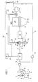
- a first reduction reactor designed as a shaft furnace 1, according to FIG. 1 to 4 in a known manner via a line 2 particulate, iron oxide-containing material, preferably lumpy iron ore, and any supplements supplied.
- reducing gas Via a feed line 3 reducing gas is blown into the reduction shaft furnace 1, which is counter to the flow of sinking iron ore rises and the reduction in use in the Reduction zone 4 causes.
- this gas After flowing through the shaft furnace 1, this gas is considered Export gas discharged via an export gas discharge line 5.
- the iron in the form of Sponge iron contains, in a melter gasifier 7.
- the melter gasifier 7 is in known manner via a line 8 a lumpy carbon carrier, for example in the form of lignite high-temperature coke and optionally as coal, and also via one Line 9 is supplied with an oxygen-containing gas.
- Iron sponge is understood to mean a solid end or intermediate product which consists of a Iron oxide is formed by direct reduction, etc. exclusively via the fixed phase, i.e. without the need to go through a liquid intermediate.
- the miller or sponge iron falls from practice in the melter gasifier 7 Melting gasification zone 10 formed on a formed from lumpy carbon carriers Fluid bed or fluidized bed, which is maintained by the blown-in oxygen-containing gas becomes. By burning the coke and possibly the coal under the influence of the oxygen-containing gas is generated in the fluidized bed or fluidized bed so much heat that the Sponge iron melts. In the molten state, it is finished by the carbon reduced so that there is a pig iron melt at the bottom of the melting gasifier 7 Steel preliminary product accumulates in the liquid state. One forms over the pig iron melt Slag melt out. These two melts are over at predetermined time intervals correspondingly arranged taps 11, 12 deducted.
- a reducing gas consisting essentially of CO and H 2 is generated, which is drawn off from the melting gasifier 7 via the feed line 3 and fed to the reduction shaft furnace 1.
- the reducing gas formed in the melter gasifier 7 is cleaned and cooled to the temperature required for direct reduction in a manner known per se via dust separators or scrubbers, but this is not shown in the drawing.
- the export gas drawn off via the export gas discharge line 5 is first subjected to cleaning, for example in a cyclone 13 or a scrubber, in order to free it of dust particles.
- the export gas then reaches a CO 2 elimination system 15 with the aid of a compressor 14, in which it is largely freed of CO 2 and at the same time of H 2 S.
- the CO 2 elimination system is designed, for example, as a pressure swing adsorption system or as a CO 2 scrubber.
- the export gas cleaned in this way is used as reducing gas via a reducing gas supply line 16 a further reduction reactor which is designed as a reduction shaft furnace 17 and just as the first reduction shaft furnace 1 works in the counterflow principle.
- This shaft furnace 17 is supplied with particulate ore, which is supplied via the ore feed line 18 is directly reduced.
- At 19 is a discharge device for in the shaft furnace 17 from the ore formed formed sponge iron.
- the export gas for CO 2 purification is to be cooled to a temperature level required for this purpose, it is subjected to heating before being introduced into the further reduction shaft furnace 17.
- the heating takes place in two stages: First, the cleaned export gas is subjected to indirect heating in a first stage, the heating device 20 used for this purpose being designed as a heat exchanger.
- the heat exchanger (recuperator) 20 has a burner 21, to which an oxygen-containing gas, such as air, is supplied as fuel gas via a line 22 and purified export gas which is drawn off from the further reduction shaft furnace 17 and fed in via a branch line 23.
- the heating in the heat exchanger 20 takes place to a temperature which is just compatible with the bundle material.
- the reducing gas which has been recuperatively heated in the first stage, is further heated in a second stage to the reducing gas temperature required for the reduction, namely by a partial combustion in the afterburning device 24, in which part of the export gas cleaned of CO 2 , which is supplied via the branch line 16 '
- the reducing gas supply line 16 is branched off, is burned with oxygen supply 25.
- high purity oxygen is used, whereby the reducing gas reaches the temperature required for the reduction in the further reduction shaft furnace 17 with a minimal amount of export gas to be burned.
- the required temperature range is between 600 and 900 ° C.
- Another part of the export gas produced in the further reduction shaft furnace 17 is also fed via a compressor 30 to the CO 2 elimination system 15 via a conveying line 31 which leads into the export gas discharge line 5 and is then also the CO 2 elimination system 15 and then as Recycle reducing gas available for the further reduction process.
- the part of the export gas of the reduction shaft furnace 17 which is not required for the method according to the invention is supplied as an export gas via the export gas line 26 for other purposes.
- the CO 2 -containing exhaust gas separated from the CO 2 elimination system 15 is expediently admixed via an exhaust gas line 32 to the part of the export gas fed to the burner 21 of the heat exchanger 20 via the branch line 23, advantageously before this branch line 23 passes through the heat exchanger 28.
- a branch line 33 branching off the exhaust gas line 32, optionally with a desulfurization device 34, with which a part of the CO 2 -containing exhaust gas is mixed with the export gas, can also lead into the export gas discharge line 26.
- this is in the burner 21 of the heat exchanger 20 Flue gas formed is discharged via a flue gas discharge line 35, being in the flue gas discharge line 35 a heat exchanger 36 is provided for heating oxygen.
- This oxygen will via the oxygen supply 25 that takes place in the afterburning device 24 Partial combustion process supplied.
- One heats up by heating the oxygen Minimize oxygen consumption and also minimize consumption for those Partial combustion reducing gas used.
- the Heat exchanger 20 formed flue gas additionally air with the help of another in the Provided flue gas discharge heat exchanger 37 and this heated air to the Burner 21 of the heat exchanger 20 is fed via the line 22. This allows the Amount of the export gas supplied to the burner 21 of this heat exchanger 20 reduce.
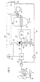
- Fig. 4 illustrates a simplified method variant in which the burner 21 of the Export gas supplied to heat exchanger 20 and originating from the further reduction process is fed into a heat exchanger 28 without prior heating.
- this Process variant is only the sensible heat contained in the flue gas for the Oxygen heating of the oxygen supplied to the partial combustion is used.
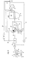
- FIG. 5 illustrates a variant of the method shown in FIG. 1, the method according to FIG. 5 being different from the method according to FIG. Fig. 1 differs in that the branched off via the branch line 23 export gas is no longer passed through the heat exchanger 28, but is directed directly to the burner 21 of the heat exchanger 20.
- the calorific value of the branched export gas is retained and this high-quality export gas is available to the burner 21 as a supporting fuel gas. Since the exhaust gas discharged in the exhaust line 32 from the CO 2 elimination system 15 is no longer mixed with the export gas branched off via the branch line 23, but is heated unmixed in the heat exchanger 28, it reaches a higher temperature level; it is fed to the burner 21 separately from the branched export gas.
- This embodiment also has the advantage that the pressure loss in the branch line 23 is lower than in the variant shown in FIG. 1, since this line 23 no longer leads via the heat exchanger 28.
- the exhaust gas originating from the CO 2 elimination system 15 is no longer enriched by the branched export gas, so that its ignitability is not increased, but this is improved by improving the ignition limits of this exhaust gas by means of those taking place in the heat exchanger 28 Temperature increase in combination with an auxiliary burner operated by the branched export gas is more than weighed out.
- the expon gas branched off via line 23 is also no longer mixed with the exhaust gas from the CO 2 elimination system 15, but rather both gases are fed separately to the burner 21 four heating device 20. again the branched export gas assumes a support burning function.
- the invention is not limited to those set out in the description of the figures Embodiments, but can be modified in various ways.
- the shaft furnace 1 instead of the fixed bed method to also provide for a reduction of fine ore in the fluidized bed process, i.e. the shaft furnace 1 to be replaced by one or more fluidized bed reactors.
- This also applies to the rest Reduction process, i.e. that the reduction shaft furnace 17 by fluidized bed reactors, in which fine ore is reduced in the fluidized bed process can be replaced.
- the heat exchanger 36 is connected upstream of the heat exchanger 20 for heating oxygen, so that the hot gases generated in the burner 21 first heat the oxygen and only then the cleaned export gas.
- the oxygen can be heated to a higher temperature and can therefore be used in a smaller amount. This results in an additional advantage that less CO and H 2 are converted in the afterburning device 24, so that the CO / CO 2 and H 2 / H 2 O ratios can be further improved.
- oxygen is also via the line 25 fed to the afterburning device 24, in which a hot gas of 4.755 ° C is formed.
- This hot gas is in the afterburning device 24 in the Heat exchanger 20 mixed to 514 ° C heated export gas, so that ultimately one Reducing gas with a temperature of about 800 ° C is generated, which over the Reduction gas supply line 16 is fed to the further reduction shaft furnace 17.
- the amount of oxygen supplied can also be reduced here, and a CO / CO 2 ratio is obtained which is 3.2% better than in the prior art.
- the H 2 / H 2 O ratio improves by 7.8%.
- the heat exchanger 36 is arranged upstream of the heat exchanger 20, so that the hot gases guided in the burner 21 first flow through the heat exchanger 36 and only then the heat exchanger 20, the oxygen is heated to 500 ° C., so that this can be further reduced in its quantity for the combustion in the afterburning device 24.
- hot gas is formed at a temperature of 5,051 ° C, which, when mixed with the remaining export gas heated to 514 ° C, becomes a reducing gas at a temperature of 800 ° C and results in a 3.9% improvement in the CO / CO 2 ratio.
- the H 2 / H 2 O ratio improves by 8.9%.
- the advantage of heating the CO 2 -containing exhaust gas separated from the CO 2 elimination system 1 via the exhaust gas line 32 in the heat exchanger 28 is explained below, but in the heat exchanger 28 only CO 2 -containing exhaust gas and no via the line 26 from the further reduction shaft furnace 17 escaping export gas is heated.
- the CO 2 -containing exhaust gas separated from the CO 2 elimination system 15 has a temperature of 45 ° C. and is heated in the heat exchanger 2X to increase the ignitability, etc. to a temperature of about 280 ° C.
- Such heating of the exhaust gas has the advantage that no export gas of the further reduction process has to be supplied for combustion thereof.
- the CO 2 -containing exhaust gas thus heated to 280 ° C. is fed to the burner 21 via line 23 and burned there with non-preheated air, that is to say air at approximately 25 ° C.
- a hot gas with a temperature of 851 ° C is formed. by means of which 20 export gas from the first reduction process can be heated in the heat exchanger. This heating of the CO 2 -containing exhaust gas above the ignition temperature makes it possible. to completely recirculate the export gas which arises in the further reduction process via line 31 and thus to be fully used for direct reduction.
Landscapes
- Chemical & Material Sciences (AREA)
- Engineering & Computer Science (AREA)
- Manufacturing & Machinery (AREA)
- Materials Engineering (AREA)
- Metallurgy (AREA)
- Organic Chemistry (AREA)
- Dispersion Chemistry (AREA)
- Waste-Gas Treatment And Other Accessory Devices For Furnaces (AREA)
- Manufacture Of Iron (AREA)
- Chemical Treatment Of Metals (AREA)
- Physical Or Chemical Processes And Apparatus (AREA)
- Carbon And Carbon Compounds (AREA)
- Catalysts (AREA)
Description
Claims (15)
- Verfahren zur Herstellung von flüssigem Roheisen oder flüssigen Stahlvorprodukten und Eisenschwamm aus von Eisenerz, vorzugsweise in Stück- und/oder Pelletform, und gegebenenfalls Zuschlägen gebildeten Einsatzstoffen, wobei die Einsatzstoffe in einer ersten Reduktionszone (4) zu Eisenschwamm direkt reduziert werden, der Eisenschwamm in einer Einschmelz-Vergasungszone (10) unter Zufuhr von Kohlenstoffträgern und sauerstoffhältigem Gas erschmolzen und ein CO- und H2-hältiges Reduktionsgas erzeugt wird, welches in die erste Reduktionszone (4) eingeleitet, dort umgesetzt und als Exportgas abgezogen wird, und wobei das abgezogene Exportgas einer CO2-Eliminierung sowie einer Aufheizung unterzogen wird und als zumindest weitgehend CO2-freies Reduktionsgas mindestens einer weiteren Reduktionszone (29) zur Direktreduktion von weiterem Eisenerz zugeführt und nach Umsetzung mit dem Eisenerz als Exportgas abgezogen wird, dadurch gekennzeichnet, daß für die Aufheizung des aus der ersten Reduktionszone (4) stammenden Exportgases Wärme des der weiteren Reduktionszone (29) austretenden Exportgases ohne Mischung der beiden Exportgase eingesetzt wird.
- Verfahren nach Anspruch 1, dadurch gekennzeichnet, daß zur Aufheizung dem aus der weiteren Reduktionszone (29) abgezogenen Exportgas im heißen, ungewaschenen Zustand fühlbare Wärme rekuperativ entzogen wird und dem aus der ersten Reduktionszone (4) stammenden Exportgas über einen Wärmeträger übermittelt wird (Fig. 1 bis 3).
- Verfahren nach Anspruch 2, dadurch gekennzeichnet, daß der Wärmeträger von gewaschenem Exportgas der weiteren Reduktionszone (29) gebildet ist.
- Verfahren nach Anspruch 3, dadurch gekennzeichnet, daß zur Aufheizung des aus dem ersten Reduktionsprozeß stammenden Exportgases aus der weiteren Reduktionszone (29) abgezogenes Exportgas nach einer Wäsche rekuperativ von ungewaschenem Exportgas der weiteren Reduktionszone (29) erhitzt und verbrannt wird, wobei die Rauchgase das aus der ersten Reduktionszone (4) stammende Exportgas rekuperativ erhitzen (Fig. 1 bis 3).
- Verfahren nach einem oder mehreren der Ansprüche 1 bis 4, dadurch gekennzeichnet, daß eine Voraufheizung des aus der ersten Reduktionszone (4) stammenden Exportgases durch Verbrennung von aus der weiteren Reduktionszone (29) stammendem Exportgas und durch rekuperativen Wärmeübergang der in den Rauchgasen enthaltenen Wärme erfolgt und anschließend eine weitere Aufheizung durch eine Teilverbrennung des aus der ersten Reduktionszone (4) stammenden Exportgases erfolgt, wobei dem Teilverbrennungsprozeß die beim weiteren Reduktionsprozeß nicht verbrauchte Wärmeenergie zugeführt wird (Fig. 1 bis 4).
- Verfahren nach Anspruch 5, dadurch gekennzeichnet, daß für die Teilverbrennung eingesetzter Sauerstoff bzw. eingesetztes sauerstoffhältiges Gas einer rekuperativen Erhitzung unterworfen wird, und zwar durch im Exportgas, stammend aus dem weiteren Reduktionsprozeß, enthaltene chemisch gebundene und/oder fühlbare Wärme (Fig. 1 bis 4).
- Verfahren nach Anspruch 6, dadurch gekennzeichnet, daß zumindest ein Teil des aus der weiteren Reduktionszone (29) abgezogenen Exportgases verbrannt wird und daß das dabei entstehende Rauchgas fühlbare Wärme an den Sauerstoff bzw. das sauerstoffhältige Gas rekuperativ abgibt (Fig. 1 bis 4).
- Verfahren nach einem oder mehreren der Ansprüche 5 bis 6, dadurch gekennzeichnet, daß ein Teil des voraufgeheizten, aus der ersten Reduktionszone (4) abgezogenen Exportgases als Brenngas zur Verbrennung desselben zusammen mit Sauerstoff bzw. einem sauerstoffhältigen Gas eingesetzt wird (Fig. 3).
- Verfahren nach einem oder mehreren der Ansprüche 4 bis 5, dadurch gekennzeichnet, daß zur Verbrennung von aus der weiteren Reduktionszone (29) stammendem Exportgas diesem Exportgas Luft beigemengt wird, die mit bei der Verbrennung von aus der weiteren Reduktionszone (29) abgezogenem Exportgas entstehendem Rauchgas rekuperativ erhitzt wird (Fig. 2, 3).
- Anlage zur Durchführung des Verfahrens nach einem oder mehreren der Ansprüche 1 bis 9, mit einem ersten Reduktionsreaktor (1) für Eisenerz, vorzugsweise in Stück- und/oder Pelletform, einem Einschmelzvergaser (7), einer den Einschmelzvergaser (7) mit dem ersten Reduktionsreaktor (1) verbindenden Zuleitung (3) für ein Reduktionsgas, einer den ersten Reduktionsreaktor (1) mit dem Einschmelzvergaser (7) verbindenden Förderleitung (6) für das im ersten Reduktionsreaktor (1) gebildete Reduktionsprodukt, mit einer vom ersten Reduktionsreaktor (1) ausgehenden Exportgas-Ableitung (5), mit in den Einschmelzvergaser (7) mündenden Zuleitungen (8, 9) für sauerstoffhältige Gase und Kohlenstoffträger, einem am Einschmelzvergaser (7) vorgesehenen Abstich (11, 12) für Roheisen und Schlacke, und mit mindestens einem zusätzlichen Reduktionsreaktor (17) zur Aufnahme von weiterem Eisenerz, einer Reduktionsgas-Zuleitung (16) zu diesem Reduktionsreaktor (17), einer Exportgas-Ableitung (26) aus diesem weiteren Reduktionsreaktor (17) und einer Austragsvorrichtung (19) für das in diesem weiteren Reduktionsreaktor (17) gebildete Reduktionsprodukt, wobei die Exportgas-Ableitung (5) des ersten Reduktionsreaktors (1) in eine CO2-Eliminierungsanlage (15) mündet, von der die Reduktionsgas-Zuleitung (16) des zusätzlichen Reduktionsreaktors (17) ausgeht und über eine Heizeinrichtung (20, 24) für das von CO2 gereinigte Exportgas in den zusätzlichen Reduktionsreaktor (17) mündet, dadurch gekennzeichnet, daß die Exportgas-Ableitung (26) des weiteren Reduktionsreaktors (17) in einen Wärmetauscher (28) mündet und von diesem zu einem Wäscher (27) führt, daß nach diesem Wäscher (27) eine Zweigleitung (23) von der Exportgas-Ableitung (26) abzweigt, in den Wärmetauscher (28) zwecks rekuperativer Aufheizung des abgezweigten gewaschenen Exportgases durch ungewaschenes Exportgas mündet und von diesem ausgehend der Heizeinrichtung (20) zugeführt ist (Fig. 1 bis 3).
- Anlage nach Anspruch 10, dadurch gekennzeichnet, daß die Zweigleitung (23) in einen Brenner (21) der Heizeinrichtung (20) mündet und daß das Rauchgas des Brenners (21) mittels einer Rauchgasableitung (35) über einen Wärmetauscher (36) zur rekuperativen Erhitzung eines der Heizeinrichtung (24) über eine Leitung (25) zugeführten sauerstoffhältigen Gases oder Sauerstoffes geführt ist (Fig. 1 bis 3).
- Anlage nach Anspruch 10 oder 11, dadurch gekennzeichnet, daß die Zweigleitung (23) in einen Brenner (21) der Heizeinrichtung (20) mündet und daß das Rauchgas des Brenners (21) mittels einer Rauchgasableitung (35) über einen Wärmetauscher (37) zur rekuperativen Erhitzung eines sauerstoffhältigen Gases, wie Luft, zugeführt ist, wobei die erhitzte Luft dem Brenner (21) der Heizeinrichtung (20) über eine Leitung (22) zugeführt ist (Fig. 2, 3).
- Anlage nach einem oder mehreren der Ansprüche 10 bis 12, dadurch gekennzeichnet, daß eine Zweigleitung (16") von der Reduktionsgas-Zuleitung (16) nach dem der Aufheizung des dem weiteren Reduktionsreaktor (17) zugeleiteten Reduktionsgases dienenden Wärmetauscher (20) ausgeht und in eine Nachverbrennungseinrichtung (24) zusammen mit einer Sauerstoff oder ein sauerstoffhältiges Gas zuführenden Leitung (25) mündet (Fig. 3).
- Anlage zur Durchführung des Verfahrens nach einem oder mehreren der Ansprüche 10 bis 13, mit einem ersten Reduktionsreaktor (1) für Eisenerz, vorzugsweise in Stück- und/oder Pelletform, einem Einschmelzvergaser (7), einer den Einschmelzvergaser (7) mit dem ersten Reduktionsreaktor (1) verbindenden Zuleitung (3) für ein Reduktionsgas, einer den ersten Reduktionsreaktor (1) mit dem Einschmelzvergaser (7) verbindenden Förderleitung (6) für das im ersten Reduktionsreaktor (1) gebildete Reduktionsprodukt, mit einer vom ersten Reduktionsreaktor (1) ausgehenden Exportgas-Ableitung (5), mit in den Einschmelzvergaser (7) mündenden Zuleitungen (8, 9) für sauerstoffhältige Gase und Kohlenstoffträger, einem am Einschmelzvergaser (7) vorgesehenen Abstich (11, 12) für Roheisen und Schlacke, und mit mindestens einem zusätzlichen Reduktionsreaktor (17) zur Aufnahme von weiterem Eisenerz, einer Reduktionsgas-Zuleitung (16) zu diesem Reduktionsreaktor (17), einer Exportgas-Ableitung (26) aus diesem weiteren Reduktionsreaktor (17) und einer Austragsvorrichtung (19) für das in diesem weiteren Reduktionsreaktor (17) gebildete Reduktionsprodukt, wobei die Exportgas-Ableitung (5) des ersten Reduktionsreaktors (1) in eine CO2-Eliminierungsanlage (15) mündet, von der die Reduktionsgas-Zuleitung (16) des zusätzlichen Reduktionsreaktors (17) ausgeht und über eine Heizeinrichtung (20, 24) für das von CO2 gereinigte Exportgas in den zusätzlichen Reduktionsreaktor (17) mündet, dadurch gekennzeichnet, daß von der Exportgas-Ableitung (26) des weiteren Reduktionsreaktors (17) eine Zweigleitung (23) in einen Brenner (21) der Heizeinrichtung (20) mündet und daß das Rauchgas des Brenners (21) mittels einer Rauchgasableitung (35) über einen Wärmetauscher (36) zur rekuperativen Erhitzung eines sauerstoffhältigen Gases, wie Luft, oder von Sauerstoff geführt ist und das erhitzte sauerstoffhältige Gas bzw. der Sauerstoff zur Heizeinrichtung (24) über eine Leitung (25) geführt ist (Fig. 4).
- Anlage nach Anspruch 14, dadurch gekennzeichnet, daß das erhitzte sauerstoffhältige Gas bzw. der erhitzte Sauerstoff in eine Nachverbrennungseinrichtung (24) der Heizeinrichtung zusammen mit über eine von der Reduktionsgaszuleitung (16) ausgehende Zweigleitung (16', 16") zugeleitetem Reduktionsgas mündet (Fig. 4).
Applications Claiming Priority (4)
| Application Number | Priority Date | Filing Date | Title |
|---|---|---|---|
| AT137995 | 1995-08-16 | ||
| AT0137995A AT406484B (de) | 1995-08-16 | 1995-08-16 | Verfahren zur herstellung von flüssigem roheisen oder flüssigen stahlvorprodukten und eisenschwamm sowie anlage zur durchführung des verfahrens |
| AT1379/95 | 1995-08-16 | ||
| PCT/AT1996/000140 WO1997007247A1 (de) | 1995-08-16 | 1996-08-01 | Verfahren zur herstellung von flüssigem roheisen oder flüssigen stahlvorprodukten und eisenschwamm sowie anlage zur durchführung des verfahrens |
Publications (2)
| Publication Number | Publication Date |
|---|---|
| EP0809713A1 EP0809713A1 (de) | 1997-12-03 |
| EP0809713B1 true EP0809713B1 (de) | 2000-10-04 |
Family
ID=3512610
Family Applications (1)
| Application Number | Title | Priority Date | Filing Date |
|---|---|---|---|
| EP96925588A Expired - Lifetime EP0809713B1 (de) | 1995-08-16 | 1996-08-01 | Verfahren zur herstellung von flüssigem roheisen oder flüssigen stahlvorprodukten und eisenschwamm sowie anlage zur durchführung des verfahrens |
Country Status (12)
| Country | Link |
|---|---|
| US (1) | US5846268A (de) |
| EP (1) | EP0809713B1 (de) |
| JP (1) | JPH10506682A (de) |
| KR (1) | KR100244977B1 (de) |
| CN (1) | CN1046962C (de) |
| AT (2) | AT406484B (de) |
| AU (1) | AU695747B2 (de) |
| DE (1) | DE59605961D1 (de) |
| ES (1) | ES2152544T3 (de) |
| TW (1) | TW343998B (de) |
| WO (1) | WO1997007247A1 (de) |
| ZA (1) | ZA966914B (de) |
Families Citing this family (9)
| Publication number | Priority date | Publication date | Assignee | Title |
|---|---|---|---|---|
| AT409634B (de) * | 2000-05-15 | 2002-09-25 | Voest Alpine Ind Anlagen | Verfahren und vorrichtung zur herstellung von roheisen oder flüssigen stahlvorprodukten aus eisenerzhältigen einsatzstoffen |
| US6478841B1 (en) | 2001-09-12 | 2002-11-12 | Techint Technologies Inc. | Integrated mini-mill for iron and steel making |
| CN100451133C (zh) * | 2005-09-15 | 2009-01-14 | 中冶东方工程技术有限公司 | 利用焦炉煤气生产直接还原铁的方法及其设备 |
| AT507955B1 (de) * | 2009-02-20 | 2011-02-15 | Siemens Vai Metals Tech Gmbh | Verfahren und anlage zum herstellen von substitutgas |
| EP2459755B1 (de) * | 2009-07-31 | 2014-09-03 | HYL Technologies, S.A. de C.V. | Verfahren zur herstellung von eisenschwamm mit verminderten co2-emissionen und deren vorrichtung |
| IT1402250B1 (it) | 2010-09-29 | 2013-08-28 | Danieli Off Mecc | Procedimento ed apparato per la produzione di ferro di riduzione diretta utilizzando una sorgente di gas riducente comprendente idrogeno e monossido di carbonio |
| AT511243B1 (de) * | 2011-03-17 | 2013-01-15 | Siemens Vai Metals Tech Gmbh | Hüttentechnische anlage mit effizienter abwärmenutzung |
| US9562201B2 (en) | 2014-06-28 | 2017-02-07 | Saudi Arabian Oil Company | Energy efficient apparatus employing energy efficient process schemes providing enhanced integration of gasification-based multi-generation and hydrocarbon refining facilities and related methods |
| EP3239306A1 (de) * | 2016-04-27 | 2017-11-01 | Primetals Technologies Austria GmbH | Verfahren und vorrichtung zur herstellung von flüssigem roheisen |
Family Cites Families (7)
| Publication number | Priority date | Publication date | Assignee | Title |
|---|---|---|---|---|
| DE2459876B1 (de) * | 1974-12-18 | 1976-06-24 | Thyssen Purofer Gmbh | Anlage fuer die direktreduktion von eisenerzen |
| US4173465A (en) * | 1978-08-15 | 1979-11-06 | Midrex Corporation | Method for the direct reduction of iron using gas from coal |
| DE3626027A1 (de) * | 1986-08-01 | 1988-02-11 | Metallgesellschaft Ag | Verfahren zur reduktion feinkoerniger, eisenhaltiger materialien mit festen kohlenstoffhaltigen reduktionsmitteln |
| DE3713630A1 (de) * | 1987-04-23 | 1988-11-17 | Voest Alpine Ag | Huettenwerk und verfahren zur erzeugung von stahl |
| DE4037977A1 (de) * | 1990-11-29 | 1992-06-11 | Voest Alpine Ind Anlagen | Verfahren zur herstellung von roheisen bzw. eisenschwamm |
| AT396255B (de) * | 1991-09-19 | 1993-07-26 | Voest Alpine Ind Anlagen | Anlage und verfahren zur erzeugung von roheisen und eisenschwamm |
| AT404254B (de) * | 1993-07-05 | 1998-10-27 | Voest Alpine Ind Anlagen | Verfahren und anlage zur herstellung von roheisen oder flüssigen stahlvorprodukten aus eisenerzhältigen einsatzstoffen |
-
1995
- 1995-08-16 AT AT0137995A patent/AT406484B/de not_active IP Right Cessation
-
1996
- 1996-07-23 TW TW085108963A patent/TW343998B/zh active
- 1996-08-01 US US08/817,151 patent/US5846268A/en not_active Expired - Fee Related
- 1996-08-01 AU AU66058/96A patent/AU695747B2/en not_active Ceased
- 1996-08-01 DE DE59605961T patent/DE59605961D1/de not_active Expired - Fee Related
- 1996-08-01 EP EP96925588A patent/EP0809713B1/de not_active Expired - Lifetime
- 1996-08-01 ES ES96925588T patent/ES2152544T3/es not_active Expired - Lifetime
- 1996-08-01 AT AT96925588T patent/ATE196779T1/de active
- 1996-08-01 WO PCT/AT1996/000140 patent/WO1997007247A1/de not_active Ceased
- 1996-08-01 CN CN96190922A patent/CN1046962C/zh not_active Expired - Fee Related
- 1996-08-01 JP JP9508731A patent/JPH10506682A/ja active Pending
- 1996-08-01 KR KR1019970702492A patent/KR100244977B1/ko not_active Expired - Fee Related
- 1996-08-15 ZA ZA9606914A patent/ZA966914B/xx unknown
Also Published As
| Publication number | Publication date |
|---|---|
| ES2152544T3 (es) | 2001-02-01 |
| ZA966914B (en) | 1997-02-27 |
| ATE196779T1 (de) | 2000-10-15 |
| TW343998B (en) | 1998-11-01 |
| CN1046962C (zh) | 1999-12-01 |
| AT406484B (de) | 2000-05-25 |
| US5846268A (en) | 1998-12-08 |
| AU6605896A (en) | 1997-03-12 |
| KR100244977B1 (ko) | 2000-03-02 |
| ATA137995A (de) | 1999-10-15 |
| WO1997007247A1 (de) | 1997-02-27 |
| KR970707305A (ko) | 1997-12-01 |
| JPH10506682A (ja) | 1998-06-30 |
| CN1161063A (zh) | 1997-10-01 |
| AU695747B2 (en) | 1998-08-20 |
| EP0809713A1 (de) | 1997-12-03 |
| DE59605961D1 (de) | 2000-11-09 |
Similar Documents
| Publication | Publication Date | Title |
|---|---|---|
| AT507113B1 (de) | Verfahren und anlage zur energie- und co2-emissionsoptimierten eisenerzeugung | |
| EP0126391B2 (de) | Verfahren zur Eisenherstellung | |
| AT403056B (de) | Verfahren und anlage zur herstellung von flüssigem roheisen oder flüssigen stahlvorprodukten und heissbrikettiertem eisen | |
| DE2401909C3 (de) | Verfahren zur Herstellung von Stahl | |
| EP0796350B1 (de) | Verfahren zur herstellung von flüssigem roheisen oder flüssigen stahlvorprodukten und anlage zur durchführung des verfahrens | |
| EP0487856B1 (de) | Verfahren zur Herstellung von Roheisen bzw. Eisenschwamm | |
| AT406380B (de) | Verfahren zum herstellen von flüssigem roheisen oder flüssigen stahlvorprodukten sowie anlage zur durchführung des verfahrens | |
| AT405186B (de) | Anlage und verfahren zur herstellung von roheisen und/oder eisenschwamm | |
| AT405187B (de) | Verfahren zum herstellen von eisenschwamm sowie anlage zur durchführung des verfahrens | |
| EP0809713B1 (de) | Verfahren zur herstellung von flüssigem roheisen oder flüssigen stahlvorprodukten und eisenschwamm sowie anlage zur durchführung des verfahrens | |
| AT409634B (de) | Verfahren und vorrichtung zur herstellung von roheisen oder flüssigen stahlvorprodukten aus eisenerzhältigen einsatzstoffen | |
| AT507713B1 (de) | Verfahren und vorrichtung zur herstellung von roheisen oder flüssigen stahlvorprodukten | |
| EP0783591B1 (de) | Verfahren zur herstellung von flüssigem roheisen oder stahlvorprodukten und anlage zur durchführung des verfahrens | |
| EP0183677A3 (de) | Verfahren und Anlage zur Direktreduktion von Eisenoxidteilchen und zum Einschmelzen der erhaltenen Eisenschwammpartikel in einem Einschmelzvergaser | |
| DE2132150A1 (de) | Verfahren zum direkten herstellen von stahl | |
| DE3530240A1 (de) | Verfahren zum schmelzen von zumindest teilweise reduziertem eisenerz, vorrichtung zur durchfuehrung dieses verfahrens sowie verwendung der reaktionsgase und gichtgase einer derartigen vorrichtung | |
| AT404254B (de) | Verfahren und anlage zur herstellung von roheisen oder flüssigen stahlvorprodukten aus eisenerzhältigen einsatzstoffen | |
| AT406381B (de) | Anlage und verfahren zur herstellung von metallschwamm | |
| EP0946758B1 (de) | Verfahren zur herstellung von flüssigem metall | |
| EP0871783A1 (de) | Verfahren zum herstellen von eisenschwamm | |
| AT405524B (de) | Verfahren zur herstellung von flüssigem roheisen oder flüssigen stahlvorprodukten und metallschwamm | |
| AT404598B (de) | Verfahren und anlage zur herstellung von fluessigem roheisen oder fluessigen stahlvorprodukten | |
| DE10227056A1 (de) | Verfahren zur Roheisenerzeugung in einem Sauerstoff-Hochofen |
Legal Events
| Date | Code | Title | Description |
|---|---|---|---|
| PUAI | Public reference made under article 153(3) epc to a published international application that has entered the european phase |
Free format text: ORIGINAL CODE: 0009012 |
|
| 17P | Request for examination filed |
Effective date: 19970827 |
|
| AK | Designated contracting states |
Kind code of ref document: A1 Designated state(s): AT BE CH DE DK ES FI FR GB GR IE IT LI LU MC NL PT SE |
|
| 17Q | First examination report despatched |
Effective date: 19991001 |
|
| GRAG | Despatch of communication of intention to grant |
Free format text: ORIGINAL CODE: EPIDOS AGRA |
|
| 17Q | First examination report despatched |
Effective date: 19991001 |
|
| GRAG | Despatch of communication of intention to grant |
Free format text: ORIGINAL CODE: EPIDOS AGRA |
|
| GRAH | Despatch of communication of intention to grant a patent |
Free format text: ORIGINAL CODE: EPIDOS IGRA |
|
| GRAH | Despatch of communication of intention to grant a patent |
Free format text: ORIGINAL CODE: EPIDOS IGRA |
|
| GRAA | (expected) grant |
Free format text: ORIGINAL CODE: 0009210 |
|
| AK | Designated contracting states |
Kind code of ref document: B1 Designated state(s): AT BE CH DE DK ES FI FR GB GR IE IT LI LU MC NL PT SE |
|
| PG25 | Lapsed in a contracting state [announced via postgrant information from national office to epo] |
Ref country code: NL Free format text: LAPSE BECAUSE OF FAILURE TO SUBMIT A TRANSLATION OF THE DESCRIPTION OR TO PAY THE FEE WITHIN THE PRESCRIBED TIME-LIMIT Effective date: 20001004 Ref country code: IT Free format text: LAPSE BECAUSE OF FAILURE TO SUBMIT A TRANSLATION OF THE DESCRIPTION OR TO PAY THE FEE WITHIN THE PRESCRIBED TIME-LIMIT;WARNING: LAPSES OF ITALIAN PATENTS WITH EFFECTIVE DATE BEFORE 2007 MAY HAVE OCCURRED AT ANY TIME BEFORE 2007. THE CORRECT EFFECTIVE DATE MAY BE DIFFERENT FROM THE ONE RECORDED. Effective date: 20001004 Ref country code: IE Free format text: LAPSE BECAUSE OF NON-PAYMENT OF DUE FEES Effective date: 20001004 Ref country code: FI Free format text: LAPSE BECAUSE OF FAILURE TO SUBMIT A TRANSLATION OF THE DESCRIPTION OR TO PAY THE FEE WITHIN THE PRESCRIBED TIME-LIMIT Effective date: 20001004 |
|
| REF | Corresponds to: |
Ref document number: 196779 Country of ref document: AT Date of ref document: 20001015 Kind code of ref document: T |
|
| REG | Reference to a national code |
Ref country code: CH Ref legal event code: EP |
|
| REG | Reference to a national code |
Ref country code: IE Ref legal event code: FG4D Free format text: GERMAN |
|
| REF | Corresponds to: |
Ref document number: 59605961 Country of ref document: DE Date of ref document: 20001109 |
|
| ET | Fr: translation filed | ||
| GBT | Gb: translation of ep patent filed (gb section 77(6)(a)/1977) |
Effective date: 20001116 |
|
| PG25 | Lapsed in a contracting state [announced via postgrant information from national office to epo] |
Ref country code: SE Free format text: LAPSE BECAUSE OF FAILURE TO SUBMIT A TRANSLATION OF THE DESCRIPTION OR TO PAY THE FEE WITHIN THE PRESCRIBED TIME-LIMIT Effective date: 20010104 Ref country code: PT Free format text: LAPSE BECAUSE OF FAILURE TO SUBMIT A TRANSLATION OF THE DESCRIPTION OR TO PAY THE FEE WITHIN THE PRESCRIBED TIME-LIMIT Effective date: 20010104 Ref country code: DK Free format text: LAPSE BECAUSE OF FAILURE TO SUBMIT A TRANSLATION OF THE DESCRIPTION OR TO PAY THE FEE WITHIN THE PRESCRIBED TIME-LIMIT Effective date: 20010104 |
|
| PG25 | Lapsed in a contracting state [announced via postgrant information from national office to epo] |
Ref country code: GR Free format text: LAPSE BECAUSE OF FAILURE TO SUBMIT A TRANSLATION OF THE DESCRIPTION OR TO PAY THE FEE WITHIN THE PRESCRIBED TIME-LIMIT Effective date: 20010105 |
|
| REG | Reference to a national code |
Ref country code: ES Ref legal event code: FG2A Ref document number: 2152544 Country of ref document: ES Kind code of ref document: T3 |
|
| NLV1 | Nl: lapsed or annulled due to failure to fulfill the requirements of art. 29p and 29m of the patents act | ||
| PG25 | Lapsed in a contracting state [announced via postgrant information from national office to epo] |
Ref country code: LU Free format text: LAPSE BECAUSE OF NON-PAYMENT OF DUE FEES Effective date: 20010801 Ref country code: GB Free format text: LAPSE BECAUSE OF NON-PAYMENT OF DUE FEES Effective date: 20010801 Ref country code: AT Free format text: LAPSE BECAUSE OF NON-PAYMENT OF DUE FEES Effective date: 20010801 |
|
| PGFP | Annual fee paid to national office [announced via postgrant information from national office to epo] |
Ref country code: DE Payment date: 20010801 Year of fee payment: 6 |
|
| PG25 | Lapsed in a contracting state [announced via postgrant information from national office to epo] |
Ref country code: ES Free format text: LAPSE BECAUSE OF NON-PAYMENT OF DUE FEES Effective date: 20010802 |
|
| PLBE | No opposition filed within time limit |
Free format text: ORIGINAL CODE: 0009261 |
|
| STAA | Information on the status of an ep patent application or granted ep patent |
Free format text: STATUS: NO OPPOSITION FILED WITHIN TIME LIMIT |
|
| REG | Reference to a national code |
Ref country code: IE Ref legal event code: FD4D |
|
| PG25 | Lapsed in a contracting state [announced via postgrant information from national office to epo] |
Ref country code: LI Free format text: LAPSE BECAUSE OF NON-PAYMENT OF DUE FEES Effective date: 20010831 Ref country code: CH Free format text: LAPSE BECAUSE OF NON-PAYMENT OF DUE FEES Effective date: 20010831 Ref country code: BE Free format text: LAPSE BECAUSE OF NON-PAYMENT OF DUE FEES Effective date: 20010831 |
|
| 26N | No opposition filed | ||
| BERE | Be: lapsed |
Owner name: VOEST-ALPINE INDUSTRIEANLAGENBAU G.M.B.H. Effective date: 20010831 |
|
| PG25 | Lapsed in a contracting state [announced via postgrant information from national office to epo] |
Ref country code: MC Free format text: LAPSE BECAUSE OF NON-PAYMENT OF DUE FEES Effective date: 20020301 |
|
| GBPC | Gb: european patent ceased through non-payment of renewal fee |
Effective date: 20010801 |
|
| REG | Reference to a national code |
Ref country code: CH Ref legal event code: PL |
|
| PG25 | Lapsed in a contracting state [announced via postgrant information from national office to epo] |
Ref country code: FR Free format text: LAPSE BECAUSE OF NON-PAYMENT OF DUE FEES Effective date: 20020430 |
|
| REG | Reference to a national code |
Ref country code: FR Ref legal event code: ST |
|
| PG25 | Lapsed in a contracting state [announced via postgrant information from national office to epo] |
Ref country code: DE Free format text: LAPSE BECAUSE OF NON-PAYMENT OF DUE FEES Effective date: 20030301 |
|
| REG | Reference to a national code |
Ref country code: ES Ref legal event code: FD2A Effective date: 20020911 |