EP0975485B1 - Krafstofftank mit integrierter ansaugstelle - Google Patents
Krafstofftank mit integrierter ansaugstelle Download PDFInfo
- Publication number
- EP0975485B1 EP0975485B1 EP99904912A EP99904912A EP0975485B1 EP 0975485 B1 EP0975485 B1 EP 0975485B1 EP 99904912 A EP99904912 A EP 99904912A EP 99904912 A EP99904912 A EP 99904912A EP 0975485 B1 EP0975485 B1 EP 0975485B1
- Authority
- EP
- European Patent Office
- Prior art keywords
- fuel
- trap
- tank
- fuel trap
- suction strainer
- Prior art date
- Legal status (The legal status is an assumption and is not a legal conclusion. Google has not performed a legal analysis and makes no representation as to the accuracy of the status listed.)
- Expired - Lifetime
Links
Images

Classifications
-
- B—PERFORMING OPERATIONS; TRANSPORTING
- B60—VEHICLES IN GENERAL
- B60K—ARRANGEMENT OR MOUNTING OF PROPULSION UNITS OR OF TRANSMISSIONS IN VEHICLES; ARRANGEMENT OR MOUNTING OF PLURAL DIVERSE PRIME-MOVERS IN VEHICLES; AUXILIARY DRIVES FOR VEHICLES; INSTRUMENTATION OR DASHBOARDS FOR VEHICLES; ARRANGEMENTS IN CONNECTION WITH COOLING, AIR INTAKE, GAS EXHAUST OR FUEL SUPPLY OF PROPULSION UNITS IN VEHICLES
- B60K15/00—Arrangement in connection with fuel supply of combustion engines or other fuel consuming energy converters, e.g. fuel cells; Mounting or construction of fuel tanks
- B60K15/03—Fuel tanks
- B60K15/077—Fuel tanks with means modifying or controlling distribution or motion of fuel, e.g. to prevent noise, surge, splash or fuel starvation
-
- B—PERFORMING OPERATIONS; TRANSPORTING
- B60—VEHICLES IN GENERAL
- B60K—ARRANGEMENT OR MOUNTING OF PROPULSION UNITS OR OF TRANSMISSIONS IN VEHICLES; ARRANGEMENT OR MOUNTING OF PLURAL DIVERSE PRIME-MOVERS IN VEHICLES; AUXILIARY DRIVES FOR VEHICLES; INSTRUMENTATION OR DASHBOARDS FOR VEHICLES; ARRANGEMENTS IN CONNECTION WITH COOLING, AIR INTAKE, GAS EXHAUST OR FUEL SUPPLY OF PROPULSION UNITS IN VEHICLES
- B60K15/00—Arrangement in connection with fuel supply of combustion engines or other fuel consuming energy converters, e.g. fuel cells; Mounting or construction of fuel tanks
- B60K15/03—Fuel tanks
- B60K2015/03105—Fuel tanks with supplementary interior tanks inside the fuel tank
-
- B—PERFORMING OPERATIONS; TRANSPORTING
- B60—VEHICLES IN GENERAL
- B60K—ARRANGEMENT OR MOUNTING OF PROPULSION UNITS OR OF TRANSMISSIONS IN VEHICLES; ARRANGEMENT OR MOUNTING OF PLURAL DIVERSE PRIME-MOVERS IN VEHICLES; AUXILIARY DRIVES FOR VEHICLES; INSTRUMENTATION OR DASHBOARDS FOR VEHICLES; ARRANGEMENTS IN CONNECTION WITH COOLING, AIR INTAKE, GAS EXHAUST OR FUEL SUPPLY OF PROPULSION UNITS IN VEHICLES
- B60K15/00—Arrangement in connection with fuel supply of combustion engines or other fuel consuming energy converters, e.g. fuel cells; Mounting or construction of fuel tanks
- B60K15/03—Fuel tanks
- B60K2015/03236—Fuel tanks characterised by special filters, the mounting thereof
-
- B—PERFORMING OPERATIONS; TRANSPORTING
- B60—VEHICLES IN GENERAL
- B60K—ARRANGEMENT OR MOUNTING OF PROPULSION UNITS OR OF TRANSMISSIONS IN VEHICLES; ARRANGEMENT OR MOUNTING OF PLURAL DIVERSE PRIME-MOVERS IN VEHICLES; AUXILIARY DRIVES FOR VEHICLES; INSTRUMENTATION OR DASHBOARDS FOR VEHICLES; ARRANGEMENTS IN CONNECTION WITH COOLING, AIR INTAKE, GAS EXHAUST OR FUEL SUPPLY OF PROPULSION UNITS IN VEHICLES
- B60K15/00—Arrangement in connection with fuel supply of combustion engines or other fuel consuming energy converters, e.g. fuel cells; Mounting or construction of fuel tanks
- B60K15/03—Fuel tanks
- B60K2015/03328—Arrangements or special measures related to fuel tanks or fuel handling
- B60K2015/03453—Arrangements or special measures related to fuel tanks or fuel handling for fixing or mounting parts of the fuel tank together
- B60K2015/03467—Arrangements or special measures related to fuel tanks or fuel handling for fixing or mounting parts of the fuel tank together by clip or snap fit fittings
-
- B—PERFORMING OPERATIONS; TRANSPORTING
- B60—VEHICLES IN GENERAL
- B60K—ARRANGEMENT OR MOUNTING OF PROPULSION UNITS OR OF TRANSMISSIONS IN VEHICLES; ARRANGEMENT OR MOUNTING OF PLURAL DIVERSE PRIME-MOVERS IN VEHICLES; AUXILIARY DRIVES FOR VEHICLES; INSTRUMENTATION OR DASHBOARDS FOR VEHICLES; ARRANGEMENTS IN CONNECTION WITH COOLING, AIR INTAKE, GAS EXHAUST OR FUEL SUPPLY OF PROPULSION UNITS IN VEHICLES
- B60K15/00—Arrangement in connection with fuel supply of combustion engines or other fuel consuming energy converters, e.g. fuel cells; Mounting or construction of fuel tanks
- B60K15/03—Fuel tanks
- B60K15/077—Fuel tanks with means modifying or controlling distribution or motion of fuel, e.g. to prevent noise, surge, splash or fuel starvation
- B60K2015/0777—Fuel tanks with means modifying or controlling distribution or motion of fuel, e.g. to prevent noise, surge, splash or fuel starvation in-tank reservoirs or baffles integrally manufactured with the fuel Tank
Definitions
- the present invention relates to a fuel tank comprising a integrated fuel trap.
- the suction assemblies which are integral blocks of the type comprising, from top to bottom: a fixing plate which, being subject to the upper wall of the tank to fuel, keeps the suction assembly in the use position and allows, among other things different pipes to circulate the fuel; a pump ; a portion of connected pipe at the pump; a strainer whose function is to filter the sucked fuel; and a foot suction consisting of a bowl whose function is to trap the fuel, the foot of the suction assembly resting on the lower wall of the fuel tank.
- the suction unit mounting plate must therefore be in a region of the tank coinciding with the opening for access to the tank provided on the vehicle.
- the optimal suction point which is determined to be the point of the tank most suitable for bathing in liquid fuel for all driving conditions of the vehicle, is not located in this region of the tank, that is to say vertically thereof when the tank is in position on the vehicle, the suction unit is badly positioned, given the problem of the suction of the fuel, which ultimately happens quite often.
- the present invention aims to solve this problem by proposing a reservoir fuel in which fuel is efficiently sucked in all circumstances, that is to say even if the mounting plate of the suction assembly cannot not be placed in line with the optimal suction point of the tank.
- the present invention relates to a fuel tank envelope having a bottom wall and comprising a fuel trap made integrally with its bottom wall, characterized in that the fuel trap comprises means allowing the attachment of a strainer directly on said fuel trap.
- the envelope according to the invention is made in two parts obtained by injection molding and joined by gluing or welding.
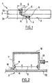
- the fuel tank of FIG. 1 comprises an envelope 1 constituted by a lower half 1 a and by an upper half 1 b joined by welding or gluing along a welding plane 3.
- the lower half 1a has no low point when the tank is horizontal, as shown, but on the contrary a plane and horizontal background 2 when the tank is in position on the vehicle.
- the optimal suction point, 4 i.e. the tank point most suitable for bathing in liquid fuel for all driving conditions of the vehicle, is located substantially in the center of the tank.
- the fuel tank 1 Due to its location in the vehicle for which it is intended, the fuel tank 1 only has an interval D, to receive the plate 5 of a suction assembly 6 without suction foot.
- a fuel trap 7 is secured to the bottom wall of the envelope, above from the optimal suction point 4, being mechanically independent of the assembly suction 6.
- the fuel trap 7 is produced by molding with the lower part of the envelope. It is therefore made in one piece with it.
- This orifice 10 may, in an embodiment not shown, but that the person skilled in the art will be able to carry out without difficulty, to be combined with the return circuit of fuel in order to create a boosting or overfeeding of the fuel trap by Venturi effect 7, which thus permanently contains a sufficient quantity of fuel to ensure the correct supply of the engine fuel system.
- the inner wall of the fuel trap 7 is provided with latching means 11 which allow the fixing of the filter strainer 9 extending over the entire horizontal section of the fuel trap 7 and filtering the fuel coming from orifice 10.
- the upper opening of the fuel trap 7 is closed by a plug 12 so as to prevent fuel from entering the fuel trap otherwise than through hole 10 and strainer 9.
- the fuel trap is further provided with a connection end piece 13 opening into the fuel trap above the strainer 9.
- This tip is designed to receive the tube portion 8 of the assembly suction 6.
- connection end piece 13 ' is integral plug 12 ', which simplifies the injection mold of the lower part of the tank, whose imprint conforms to the fuel trap at the same time as the bottom wall of the envelope.
- the fuel trap 7 "also comes from molding with the lower half of the envelope.
- latching means 11 are provided in the fuel trap for fixing a 9 "bag-shaped strainer which is suitable for filtering both the fuel that enters the fuel trap through its upper opening than the one entering the fuel trap through port 10.
- connection piece 13 ", integral with the strainer 15" is intended for receive the pipe portion 8.
Landscapes
- Engineering & Computer Science (AREA)
- Life Sciences & Earth Sciences (AREA)
- Sustainable Development (AREA)
- Sustainable Energy (AREA)
- Chemical & Material Sciences (AREA)
- Combustion & Propulsion (AREA)
- Transportation (AREA)
- Mechanical Engineering (AREA)
- Cooling, Air Intake And Gas Exhaust, And Fuel Tank Arrangements In Propulsion Units (AREA)
Claims (5)
- Behälter für die Aufnahme von Kraftstoff, der eine Ansaugstelle für Kraftstoff hat, welche einstückig mit der Wand des Bodens des Behälters hergestellt ist, dadurch gekennzeichnet, dass die Ansaugstelle (7,7'7") Mittel (11,11") aufweist, die eine Befestigung eines Saugkorbs direkt an der Ansaugstelle ermöglichen.
- Behälter nach Anspruch 1, dadurch gekennzeichnet, dass die eine Befestigung des Saugkorbs ermöglichen dem Mittel als Einklipsmittel (11,11") ausgebildet sind.
- Behälter nach einem beliebigen der Ansprüche 1 und 2, dadurch gekennzeichnet, dass der Saugkorb (9") sich über den gesamten horizontalen Querschnitt der Ansaugstelle (7, 7") für Kraftstoff erstreckt, welche nach oben so abgeschlossen (12, 12") ist, dass der Kraftstoff nur durch eine Öffnung (10"), die in der Basis der Ansaugstelle ausgebildet ist, in die Ansaugstelle hineingelangen kann, dabei ist ein Ansatz (13, 13') oberhalb des Saugkorbs (9") vorgesehen, um Kraftstoff anzusaugen.
- Behälter nach einem beliebigen der Ansprüche 1 und 2, dadurch gekennzeichnet, dass der Saugkorb (9") die Form einer Tasche hat und im Inneren der Ansaugstelle (7') für Kraftstoff befestigt ist, dabei ist ein Ansatz (13"), der mit dem Saugkorb verbunden ist, zum Ansaugen von Kraftstoff vorgesehen.
- Behälter nach einem beliebigen der Ansprüche 1 bis 4, dadurch gekennzeichnet, dass er aus zwei Teilstücken hergestellt ist die im Spritzgussverfahren aus einem Kunststoff hergestellt sind und durch Kleben oder Schweißen miteinander verbunden sind.
Applications Claiming Priority (3)
| Application Number | Priority Date | Filing Date | Title |
|---|---|---|---|
| FR9802018 | 1998-02-19 | ||
| FR9802018A FR2774948B1 (fr) | 1998-02-19 | 1998-02-19 | Reservoir a carburant a piege a carburant integre |
| PCT/FR1999/000379 WO1999042319A1 (fr) | 1998-02-19 | 1999-02-19 | Reservoir a carburant a piege a carburant integre |
Publications (2)
| Publication Number | Publication Date |
|---|---|
| EP0975485A1 EP0975485A1 (de) | 2000-02-02 |
| EP0975485B1 true EP0975485B1 (de) | 2002-12-04 |
Family
ID=9523144
Family Applications (1)
| Application Number | Title | Priority Date | Filing Date |
|---|---|---|---|
| EP99904912A Expired - Lifetime EP0975485B1 (de) | 1998-02-19 | 1999-02-19 | Krafstofftank mit integrierter ansaugstelle |
Country Status (5)
| Country | Link |
|---|---|
| EP (1) | EP0975485B1 (de) |
| CA (1) | CA2286568A1 (de) |
| DE (1) | DE69904267T2 (de) |
| FR (1) | FR2774948B1 (de) |
| WO (1) | WO1999042319A1 (de) |
Cited By (1)
| Publication number | Priority date | Publication date | Assignee | Title |
|---|---|---|---|---|
| DE102005045110A1 (de) * | 2005-09-21 | 2007-03-29 | Webasto Ag | Vorrichtung zur Entnahme von Brennstoff für eine Kraftfahrzeugheizung |
Families Citing this family (4)
| Publication number | Priority date | Publication date | Assignee | Title |
|---|---|---|---|---|
| FR2808471B1 (fr) | 2000-05-03 | 2003-02-14 | Plastic Omnium Cie | Reservoir a carburant et procede de fabrication |
| US6557581B2 (en) * | 2001-03-01 | 2003-05-06 | Raviv Precision Injection Molding | Liquid fuel trap |
| DE10327525A1 (de) * | 2003-06-17 | 2005-01-13 | Siemens Ag | Befestigungseinrichtung |
| DE102013226295B4 (de) * | 2013-12-17 | 2023-03-23 | Bayerische Motoren Werke Aktiengesellschaft | Kraftstoff-Sammeleinrichtung für einen Kraftstoffbehälter eines Kraftfahrzeuges |
Family Cites Families (7)
| Publication number | Priority date | Publication date | Assignee | Title |
|---|---|---|---|---|
| US3726310A (en) * | 1971-02-18 | 1973-04-10 | Bendix Corp | Fluid amplified auxiliary reservoir |
| FR2460196A2 (fr) * | 1979-07-04 | 1981-01-23 | Transformat Mat Plastiques | Procede d'obtention de corps monobloc par soufflage et pourvu d'une partie saillante sur l'une de ses parois interieures |
| DE3510890A1 (de) * | 1985-03-26 | 1986-10-09 | Pierburg Gmbh & Co Kg, 4040 Neuss | Kraftstoffoerdersystem |
| DE3915185C1 (de) * | 1989-05-10 | 1990-10-04 | Daimler-Benz Aktiengesellschaft, 7000 Stuttgart, De | |
| DE4023037C2 (de) * | 1990-07-20 | 1995-05-18 | Vdo Schindling | Kraftstoff-Fördersystem |
| US5127432A (en) * | 1991-09-16 | 1992-07-07 | Ford Motor Company | Fuel tank reservoir |
| DE4306973A1 (de) * | 1993-03-05 | 1994-09-08 | Kautex Werke Gmbh | Verfahren zum Herstellen von Hohlkörpern aus thermoplastischem Kunststoff |
-
1998
- 1998-02-19 FR FR9802018A patent/FR2774948B1/fr not_active Expired - Fee Related
-
1999
- 1999-02-19 EP EP99904912A patent/EP0975485B1/de not_active Expired - Lifetime
- 1999-02-19 CA CA002286568A patent/CA2286568A1/fr not_active Abandoned
- 1999-02-19 WO PCT/FR1999/000379 patent/WO1999042319A1/fr active IP Right Grant
- 1999-02-19 DE DE69904267T patent/DE69904267T2/de not_active Expired - Lifetime
Cited By (1)
| Publication number | Priority date | Publication date | Assignee | Title |
|---|---|---|---|---|
| DE102005045110A1 (de) * | 2005-09-21 | 2007-03-29 | Webasto Ag | Vorrichtung zur Entnahme von Brennstoff für eine Kraftfahrzeugheizung |
Also Published As
| Publication number | Publication date |
|---|---|
| EP0975485A1 (de) | 2000-02-02 |
| DE69904267D1 (de) | 2003-01-16 |
| DE69904267T2 (de) | 2003-11-13 |
| CA2286568A1 (fr) | 1999-08-26 |
| FR2774948A1 (fr) | 1999-08-20 |
| FR2774948B1 (fr) | 2000-05-05 |
| WO1999042319A1 (fr) | 1999-08-26 |
Similar Documents
| Publication | Publication Date | Title |
|---|---|---|
| EP1267687B1 (de) | Elektrische kaffeemaschine mit einem drehbaren wasserbehälter | |
| EP0928252B1 (de) | Kraftstoffzuführeinrichtung für einen kraftfahrzeugtank | |
| EP0588708B1 (de) | Wasch- und Wischanlage für Scheiben an Kraftfahrzeugen | |
| FR2685388A1 (fr) | Circuit d'alimentation en carburant d'un moteur a combustion interne. | |
| FR2503557A1 (fr) | Dispositif de tamis a l'interieur de puisards de lave-vaisselle | |
| FR2873330A1 (fr) | Systeme de reservoir de carburant | |
| EP0975485B1 (de) | Krafstofftank mit integrierter ansaugstelle | |
| EP0922603B1 (de) | Vorratsbehälter für den Kraftstofftank eines Kraftfahrzeuges | |
| FR2845425A1 (fr) | Appareil d'alimentation en carburant pour vehicules | |
| FR2600909A1 (fr) | Dispositif de filtration | |
| EP1135589B1 (de) | Flüssigkeitsdruckbeaufschlagungseinrichtung, insbesondere für brennstoffzusatzmittel | |
| FR2802979A1 (fr) | Installation d'alimentation en carburant d'un moteur a combustion interne de vehicule automobile | |
| FR2677597A1 (fr) | Dispositif d'ejection de liquide de lave-galce monte sur un balai d'essuie-glace. | |
| FR2683444A1 (fr) | Lave-vaisselle domestique avec corbeille superieure reglable en hauteur. | |
| FR2792620A1 (fr) | Support de poche souple et distributeur comprenant un tel support | |
| FR2609482A1 (fr) | Appareil de robinetterie pour le remplissage d'une baignoire | |
| FR2642104A1 (fr) | Dispositif de regulation de debit pour circuit de nettoyage d'un bassin, en particulier d'une piscine | |
| FR2802980A1 (fr) | Module de transfert de carburant pour vehicules automobiles | |
| FR2663991A1 (fr) | Dispositif de retention du combustible dans la conduite d'aspiration du circuit d'alimentation d'un moteur. | |
| FR3121693A1 (fr) | Dispositif d’équipement sanitaire pour cuvette de toilette | |
| FR2762361A1 (fr) | Boitier en forme de pot destine a recevoir une pompe de transfert de liquide | |
| FR2909137A1 (fr) | Dispositif d'assemblage pour un actionneur electromagnetique d'un injecteur pour moteur a combustion interne. | |
| FR2802576A1 (fr) | Module de transfert de carburant pour un vehicule automobile | |
| FR2630059A3 (fr) | Feu pour automobiles | |
| FR2784059A1 (fr) | Systeme de filtre a air pour motocycle |
Legal Events
| Date | Code | Title | Description |
|---|---|---|---|
| PUAI | Public reference made under article 153(3) epc to a published international application that has entered the european phase |
Free format text: ORIGINAL CODE: 0009012 |
|
| AK | Designated contracting states |
Kind code of ref document: A1 Designated state(s): DE ES FR GB IT SE |
|
| 17P | Request for examination filed |
Effective date: 20000211 |
|
| GRAG | Despatch of communication of intention to grant |
Free format text: ORIGINAL CODE: EPIDOS AGRA |
|
| 17Q | First examination report despatched |
Effective date: 20020206 |
|
| GRAG | Despatch of communication of intention to grant |
Free format text: ORIGINAL CODE: EPIDOS AGRA |
|
| GRAG | Despatch of communication of intention to grant |
Free format text: ORIGINAL CODE: EPIDOS AGRA |
|
| GRAH | Despatch of communication of intention to grant a patent |
Free format text: ORIGINAL CODE: EPIDOS IGRA |
|
| GRAH | Despatch of communication of intention to grant a patent |
Free format text: ORIGINAL CODE: EPIDOS IGRA |
|
| GRAA | (expected) grant |
Free format text: ORIGINAL CODE: 0009210 |
|
| AK | Designated contracting states |
Kind code of ref document: B1 Designated state(s): DE ES FR GB IT SE |
|
| PG25 | Lapsed in a contracting state [announced via postgrant information from national office to epo] |
Ref country code: IT Free format text: LAPSE BECAUSE OF FAILURE TO SUBMIT A TRANSLATION OF THE DESCRIPTION OR TO PAY THE FEE WITHIN THE PRESCRIBED TIME-LIMIT;WARNING: LAPSES OF ITALIAN PATENTS WITH EFFECTIVE DATE BEFORE 2007 MAY HAVE OCCURRED AT ANY TIME BEFORE 2007. THE CORRECT EFFECTIVE DATE MAY BE DIFFERENT FROM THE ONE RECORDED. Effective date: 20021204 |
|
| REG | Reference to a national code |
Ref country code: GB Ref legal event code: FG4D Free format text: NOT ENGLISH |
|
| REF | Corresponds to: |
Ref document number: 69904267 Country of ref document: DE Date of ref document: 20030116 |
|
| PG25 | Lapsed in a contracting state [announced via postgrant information from national office to epo] |
Ref country code: SE Free format text: LAPSE BECAUSE OF FAILURE TO SUBMIT A TRANSLATION OF THE DESCRIPTION OR TO PAY THE FEE WITHIN THE PRESCRIBED TIME-LIMIT Effective date: 20030304 |
|
| GBT | Gb: translation of ep patent filed (gb section 77(6)(a)/1977) |
Effective date: 20030314 |
|
| PG25 | Lapsed in a contracting state [announced via postgrant information from national office to epo] |
Ref country code: ES Free format text: LAPSE BECAUSE OF FAILURE TO SUBMIT A TRANSLATION OF THE DESCRIPTION OR TO PAY THE FEE WITHIN THE PRESCRIBED TIME-LIMIT Effective date: 20030627 |
|
| PLBE | No opposition filed within time limit |
Free format text: ORIGINAL CODE: 0009261 |
|
| STAA | Information on the status of an ep patent application or granted ep patent |
Free format text: STATUS: NO OPPOSITION FILED WITHIN TIME LIMIT |
|
| 26N | No opposition filed |
Effective date: 20030905 |
|
| REG | Reference to a national code |
Ref country code: FR Ref legal event code: TP |
|
| REG | Reference to a national code |
Ref country code: GB Ref legal event code: 732E |
|
| GBPC | Gb: european patent ceased through non-payment of renewal fee |
Effective date: 20070219 |
|
| PG25 | Lapsed in a contracting state [announced via postgrant information from national office to epo] |
Ref country code: GB Free format text: LAPSE BECAUSE OF NON-PAYMENT OF DUE FEES Effective date: 20070219 |
|
| PGFP | Annual fee paid to national office [announced via postgrant information from national office to epo] |
Ref country code: GB Payment date: 20060215 Year of fee payment: 8 |
|
| PGFP | Annual fee paid to national office [announced via postgrant information from national office to epo] |
Ref country code: FR Payment date: 20100223 Year of fee payment: 12 |
|
| REG | Reference to a national code |
Ref country code: FR Ref legal event code: ST Effective date: 20111102 |
|
| PG25 | Lapsed in a contracting state [announced via postgrant information from national office to epo] |
Ref country code: FR Free format text: LAPSE BECAUSE OF NON-PAYMENT OF DUE FEES Effective date: 20110228 |
|
| PGFP | Annual fee paid to national office [announced via postgrant information from national office to epo] |
Ref country code: DE Payment date: 20140227 Year of fee payment: 16 |
|
| REG | Reference to a national code |
Ref country code: DE Ref legal event code: R119 Ref document number: 69904267 Country of ref document: DE |
|
| PG25 | Lapsed in a contracting state [announced via postgrant information from national office to epo] |
Ref country code: DE Free format text: LAPSE BECAUSE OF NON-PAYMENT OF DUE FEES Effective date: 20150901 |