EP0975460B1 - Method for attaching a fastener to a surface treating article, and such an article having a fastener - Google Patents
Method for attaching a fastener to a surface treating article, and such an article having a fastener Download PDFInfo
- Publication number
- EP0975460B1 EP0975460B1 EP19970938495 EP97938495A EP0975460B1 EP 0975460 B1 EP0975460 B1 EP 0975460B1 EP 19970938495 EP19970938495 EP 19970938495 EP 97938495 A EP97938495 A EP 97938495A EP 0975460 B1 EP0975460 B1 EP 0975460B1
- Authority
- EP
- European Patent Office
- Prior art keywords
- fastener
- article
- woven scrim
- woven
- backing
- Prior art date
- Legal status (The legal status is an assumption and is not a legal conclusion. Google has not performed a legal analysis and makes no representation as to the accuracy of the status listed.)
- Expired - Lifetime
Links
- 238000000034 method Methods 0.000 title claims abstract description 37
- 230000003750 conditioning effect Effects 0.000 claims abstract description 38
- 239000000835 fiber Substances 0.000 claims description 13
- 239000004677 Nylon Substances 0.000 claims description 5
- 229920001778 nylon Polymers 0.000 claims description 5
- 230000001939 inductive effect Effects 0.000 claims description 4
- 239000012815 thermoplastic material Substances 0.000 claims description 4
- 235000004879 dioscorea Nutrition 0.000 claims 1
- 238000003466 welding Methods 0.000 abstract description 22
- 239000000463 material Substances 0.000 description 17
- 238000004519 manufacturing process Methods 0.000 description 9
- 230000001965 increasing effect Effects 0.000 description 7
- 238000005065 mining Methods 0.000 description 7
- 229920002302 Nylon 6,6 Polymers 0.000 description 6
- 239000003365 glass fiber Substances 0.000 description 4
- 239000002245 particle Substances 0.000 description 4
- 230000008569 process Effects 0.000 description 4
- 229920005989 resin Polymers 0.000 description 4
- 239000011347 resin Substances 0.000 description 4
- 229920001169 thermoplastic Polymers 0.000 description 4
- 229920001187 thermosetting polymer Polymers 0.000 description 4
- 239000004416 thermosoftening plastic Substances 0.000 description 4
- 238000000576 coating method Methods 0.000 description 3
- 239000000945 filler Substances 0.000 description 3
- 230000007246 mechanism Effects 0.000 description 3
- VTYYLEPIZMXCLO-UHFFFAOYSA-L Calcium carbonate Chemical compound [Ca+2].[O-]C([O-])=O VTYYLEPIZMXCLO-UHFFFAOYSA-L 0.000 description 2
- 239000004952 Polyamide Substances 0.000 description 2
- 239000004614 Process Aid Substances 0.000 description 2
- 239000000853 adhesive Substances 0.000 description 2
- 230000001070 adhesive effect Effects 0.000 description 2
- 239000003086 colorant Substances 0.000 description 2
- -1 copolyamides Polymers 0.000 description 2
- 238000001746 injection moulding Methods 0.000 description 2
- 239000000155 melt Substances 0.000 description 2
- 238000005498 polishing Methods 0.000 description 2
- 229920002647 polyamide Polymers 0.000 description 2
- 239000012744 reinforcing agent Substances 0.000 description 2
- 230000003014 reinforcing effect Effects 0.000 description 2
- 230000004044 response Effects 0.000 description 2
- 238000012360 testing method Methods 0.000 description 2
- 229920000049 Carbon (fiber) Polymers 0.000 description 1
- 229920001634 Copolyester Polymers 0.000 description 1
- 241001481828 Glyptocephalus cynoglossus Species 0.000 description 1
- 239000004642 Polyimide Substances 0.000 description 1
- 230000003213 activating effect Effects 0.000 description 1
- 229910000019 calcium carbonate Inorganic materials 0.000 description 1
- 239000004917 carbon fiber Substances 0.000 description 1
- 239000003795 chemical substances by application Substances 0.000 description 1
- 239000011248 coating agent Substances 0.000 description 1
- 230000000295 complement effect Effects 0.000 description 1
- 238000010276 construction Methods 0.000 description 1
- 239000000975 dye Substances 0.000 description 1
- 230000000694 effects Effects 0.000 description 1
- 239000004744 fabric Substances 0.000 description 1
- 229920002313 fluoropolymer Polymers 0.000 description 1
- 239000004811 fluoropolymer Substances 0.000 description 1
- 239000011521 glass Substances 0.000 description 1
- 230000006872 improvement Effects 0.000 description 1
- 238000002347 injection Methods 0.000 description 1
- 239000007924 injection Substances 0.000 description 1
- 238000009434 installation Methods 0.000 description 1
- HGPXWXLYXNVULB-UHFFFAOYSA-M lithium stearate Chemical compound [Li+].CCCCCCCCCCCCCCCCCC([O-])=O HGPXWXLYXNVULB-UHFFFAOYSA-M 0.000 description 1
- 238000003754 machining Methods 0.000 description 1
- 230000013011 mating Effects 0.000 description 1
- 238000005259 measurement Methods 0.000 description 1
- 229910052751 metal Inorganic materials 0.000 description 1
- 239000002184 metal Substances 0.000 description 1
- VNWKTOKETHGBQD-UHFFFAOYSA-N methane Chemical compound C VNWKTOKETHGBQD-UHFFFAOYSA-N 0.000 description 1
- 239000010445 mica Substances 0.000 description 1
- 229910052618 mica group Inorganic materials 0.000 description 1
- 238000012986 modification Methods 0.000 description 1
- 230000004048 modification Effects 0.000 description 1
- 238000000465 moulding Methods 0.000 description 1
- 229920003986 novolac Polymers 0.000 description 1
- 230000035515 penetration Effects 0.000 description 1
- 239000000049 pigment Substances 0.000 description 1
- 239000004033 plastic Substances 0.000 description 1
- 229920003023 plastic Polymers 0.000 description 1
- 229920002492 poly(sulfone) Polymers 0.000 description 1
- 229920000728 polyester Polymers 0.000 description 1
- 229920001721 polyimide Polymers 0.000 description 1
- 229920000098 polyolefin Polymers 0.000 description 1
- 229920002635 polyurethane Polymers 0.000 description 1
- 239000004814 polyurethane Substances 0.000 description 1
- 239000000843 powder Substances 0.000 description 1
- 238000010107 reaction injection moulding Methods 0.000 description 1
- 230000002787 reinforcement Effects 0.000 description 1
- 238000009987 spinning Methods 0.000 description 1
- 229920002994 synthetic fiber Polymers 0.000 description 1
- 239000012209 synthetic fiber Substances 0.000 description 1
- 238000012956 testing procedure Methods 0.000 description 1
- XOOUIPVCVHRTMJ-UHFFFAOYSA-L zinc stearate Chemical compound [Zn+2].CCCCCCCCCCCCCCCCCC([O-])=O.CCCCCCCCCCCCCCCCCC([O-])=O XOOUIPVCVHRTMJ-UHFFFAOYSA-L 0.000 description 1
Images
Classifications
-
- B—PERFORMING OPERATIONS; TRANSPORTING
- B29—WORKING OF PLASTICS; WORKING OF SUBSTANCES IN A PLASTIC STATE IN GENERAL
- B29C—SHAPING OR JOINING OF PLASTICS; SHAPING OF MATERIAL IN A PLASTIC STATE, NOT OTHERWISE PROVIDED FOR; AFTER-TREATMENT OF THE SHAPED PRODUCTS, e.g. REPAIRING
- B29C66/00—General aspects of processes or apparatus for joining preformed parts
- B29C66/40—General aspects of joining substantially flat articles, e.g. plates, sheets or web-like materials; Making flat seams in tubular or hollow articles; Joining single elements to substantially flat surfaces
- B29C66/47—Joining single elements to sheets, plates or other substantially flat surfaces
- B29C66/474—Joining single elements to sheets, plates or other substantially flat surfaces said single elements being substantially non-flat
-
- B—PERFORMING OPERATIONS; TRANSPORTING
- B24—GRINDING; POLISHING
- B24D—TOOLS FOR GRINDING, BUFFING OR SHARPENING
- B24D13/00—Wheels having flexibly-acting working parts, e.g. buffing wheels; Mountings therefor
- B24D13/20—Mountings for the wheels
-
- B—PERFORMING OPERATIONS; TRANSPORTING
- B24—GRINDING; POLISHING
- B24D—TOOLS FOR GRINDING, BUFFING OR SHARPENING
- B24D18/00—Manufacture of grinding tools or other grinding devices, e.g. wheels, not otherwise provided for
-
- B—PERFORMING OPERATIONS; TRANSPORTING
- B24—GRINDING; POLISHING
- B24D—TOOLS FOR GRINDING, BUFFING OR SHARPENING
- B24D7/00—Bonded abrasive wheels, or wheels with inserted abrasive blocks, designed for acting otherwise than only by their periphery, e.g. by the front face; Bushings or mountings therefor
- B24D7/16—Bushings; Mountings
-
- B—PERFORMING OPERATIONS; TRANSPORTING
- B29—WORKING OF PLASTICS; WORKING OF SUBSTANCES IN A PLASTIC STATE IN GENERAL
- B29C—SHAPING OR JOINING OF PLASTICS; SHAPING OF MATERIAL IN A PLASTIC STATE, NOT OTHERWISE PROVIDED FOR; AFTER-TREATMENT OF THE SHAPED PRODUCTS, e.g. REPAIRING
- B29C65/00—Joining or sealing of preformed parts, e.g. welding of plastics materials; Apparatus therefor
- B29C65/02—Joining or sealing of preformed parts, e.g. welding of plastics materials; Apparatus therefor by heating, with or without pressure
- B29C65/06—Joining or sealing of preformed parts, e.g. welding of plastics materials; Apparatus therefor by heating, with or without pressure using friction, e.g. spin welding
- B29C65/0672—Spin welding
-
- B—PERFORMING OPERATIONS; TRANSPORTING
- B29—WORKING OF PLASTICS; WORKING OF SUBSTANCES IN A PLASTIC STATE IN GENERAL
- B29C—SHAPING OR JOINING OF PLASTICS; SHAPING OF MATERIAL IN A PLASTIC STATE, NOT OTHERWISE PROVIDED FOR; AFTER-TREATMENT OF THE SHAPED PRODUCTS, e.g. REPAIRING
- B29C66/00—General aspects of processes or apparatus for joining preformed parts
- B29C66/01—General aspects dealing with the joint area or with the area to be joined
- B29C66/05—Particular design of joint configurations
- B29C66/10—Particular design of joint configurations particular design of the joint cross-sections
- B29C66/11—Joint cross-sections comprising a single joint-segment, i.e. one of the parts to be joined comprising a single joint-segment in the joint cross-section
- B29C66/112—Single lapped joints
- B29C66/1122—Single lap to lap joints, i.e. overlap joints
-
- B—PERFORMING OPERATIONS; TRANSPORTING
- B29—WORKING OF PLASTICS; WORKING OF SUBSTANCES IN A PLASTIC STATE IN GENERAL
- B29C—SHAPING OR JOINING OF PLASTICS; SHAPING OF MATERIAL IN A PLASTIC STATE, NOT OTHERWISE PROVIDED FOR; AFTER-TREATMENT OF THE SHAPED PRODUCTS, e.g. REPAIRING
- B29C66/00—General aspects of processes or apparatus for joining preformed parts
- B29C66/80—General aspects of machine operations or constructions and parts thereof
- B29C66/82—Pressure application arrangements, e.g. transmission or actuating mechanisms for joining tools or clamps
- B29C66/824—Actuating mechanisms
- B29C66/8242—Pneumatic or hydraulic drives
-
- B—PERFORMING OPERATIONS; TRANSPORTING
- B29—WORKING OF PLASTICS; WORKING OF SUBSTANCES IN A PLASTIC STATE IN GENERAL
- B29C—SHAPING OR JOINING OF PLASTICS; SHAPING OF MATERIAL IN A PLASTIC STATE, NOT OTHERWISE PROVIDED FOR; AFTER-TREATMENT OF THE SHAPED PRODUCTS, e.g. REPAIRING
- B29C66/00—General aspects of processes or apparatus for joining preformed parts
- B29C66/80—General aspects of machine operations or constructions and parts thereof
- B29C66/83—General aspects of machine operations or constructions and parts thereof characterised by the movement of the joining or pressing tools
- B29C66/832—Reciprocating joining or pressing tools
- B29C66/8322—Joining or pressing tools reciprocating along one axis
-
- B—PERFORMING OPERATIONS; TRANSPORTING
- B29—WORKING OF PLASTICS; WORKING OF SUBSTANCES IN A PLASTIC STATE IN GENERAL
- B29C—SHAPING OR JOINING OF PLASTICS; SHAPING OF MATERIAL IN A PLASTIC STATE, NOT OTHERWISE PROVIDED FOR; AFTER-TREATMENT OF THE SHAPED PRODUCTS, e.g. REPAIRING
- B29C66/00—General aspects of processes or apparatus for joining preformed parts
- B29C66/40—General aspects of joining substantially flat articles, e.g. plates, sheets or web-like materials; Making flat seams in tubular or hollow articles; Joining single elements to substantially flat surfaces
- B29C66/41—Joining substantially flat articles ; Making flat seams in tubular or hollow articles
- B29C66/45—Joining of substantially the whole surface of the articles
- B29C66/452—Joining of substantially the whole surface of the articles the article having a disc form, e.g. making CDs or DVDs
-
- B—PERFORMING OPERATIONS; TRANSPORTING
- B29—WORKING OF PLASTICS; WORKING OF SUBSTANCES IN A PLASTIC STATE IN GENERAL
- B29C—SHAPING OR JOINING OF PLASTICS; SHAPING OF MATERIAL IN A PLASTIC STATE, NOT OTHERWISE PROVIDED FOR; AFTER-TREATMENT OF THE SHAPED PRODUCTS, e.g. REPAIRING
- B29C66/00—General aspects of processes or apparatus for joining preformed parts
- B29C66/70—General aspects of processes or apparatus for joining preformed parts characterised by the composition, physical properties or the structure of the material of the parts to be joined; Joining with non-plastics material
- B29C66/71—General aspects of processes or apparatus for joining preformed parts characterised by the composition, physical properties or the structure of the material of the parts to be joined; Joining with non-plastics material characterised by the composition of the plastics material of the parts to be joined
-
- B—PERFORMING OPERATIONS; TRANSPORTING
- B29—WORKING OF PLASTICS; WORKING OF SUBSTANCES IN A PLASTIC STATE IN GENERAL
- B29C—SHAPING OR JOINING OF PLASTICS; SHAPING OF MATERIAL IN A PLASTIC STATE, NOT OTHERWISE PROVIDED FOR; AFTER-TREATMENT OF THE SHAPED PRODUCTS, e.g. REPAIRING
- B29C66/00—General aspects of processes or apparatus for joining preformed parts
- B29C66/70—General aspects of processes or apparatus for joining preformed parts characterised by the composition, physical properties or the structure of the material of the parts to be joined; Joining with non-plastics material
- B29C66/73—General aspects of processes or apparatus for joining preformed parts characterised by the composition, physical properties or the structure of the material of the parts to be joined; Joining with non-plastics material characterised by the intensive physical properties of the material of the parts to be joined, by the optical properties of the material of the parts to be joined, by the extensive physical properties of the parts to be joined, by the state of the material of the parts to be joined or by the material of the parts to be joined being a thermoplastic or a thermoset
- B29C66/731—General aspects of processes or apparatus for joining preformed parts characterised by the composition, physical properties or the structure of the material of the parts to be joined; Joining with non-plastics material characterised by the intensive physical properties of the material of the parts to be joined, by the optical properties of the material of the parts to be joined, by the extensive physical properties of the parts to be joined, by the state of the material of the parts to be joined or by the material of the parts to be joined being a thermoplastic or a thermoset characterised by the intensive physical properties of the material of the parts to be joined
- B29C66/7316—Surface properties
- B29C66/73161—Roughness or rugosity
-
- B—PERFORMING OPERATIONS; TRANSPORTING
- B29—WORKING OF PLASTICS; WORKING OF SUBSTANCES IN A PLASTIC STATE IN GENERAL
- B29L—INDEXING SCHEME ASSOCIATED WITH SUBCLASS B29C, RELATING TO PARTICULAR ARTICLES
- B29L2031/00—Other particular articles
- B29L2031/727—Fastening elements
Definitions
- the present invention relates generally to a method of spin welding a fastener to an article and such an article, and more particularly to a method of spin welding a fastener to a surface conditioning disc and such a disc.
- U.S. Patent No. 3,562,968 to Johnson et al. discloses a surface treating tool providing for easy installation of the surface treating article.
- the surface treating article has adhered thereto a drive button that engages a complementary cylindrical opening in a drive assembly comprising a back-up pad which is driven by a driving means.
- the adhesively-bonded drive button provides for quick and easy attachment and removal of surface treating elements without special mounting tools.
- Surface conditioning discs having a threaded male button bonded to the back side of the disc by an adhesive are available commercially as RolocTM surface conditioning discs from Minnesota Mining and Manufacturing Company, St. Paul, Minnesota. These surface conditioning discs have on the front side a conformable, three-dimensional non-woven open web material formed of synthetic fibers and abrasive particles. This web is needle tacked to an open weave scrim backing.
- U.S. Patent No. 3,688,453 to Legacy et al. describes abrasive articles which comprise a lofty non-woven web needle tacked to a woven backing and impregnated with resin and abrasive.
- U.S. Patent No. 3,851,357, "Fastener,” (Ribich et al.) discloses a fastening structure and method of making same which comprises a fastener member having a base element and a plurality of hooking elements projecting from one surface of the base element.
- the fastening structure also comprises a snap fastening member having a base member and a holding means protruding centrally from one side of the base member for attaching the snap fastening member to a mounting plate.
- the fastening member and snap fastening member are secured together in a melt-bonded relationship.
- the hook-type hooking elements and base element of the fastening member are molded of a thermoplastic material as an integral unit.
- the fastening tape member may comprise a woven or knitted thermoplastic material such as described in U.S. Patent No. 2,717,437, "Velvet Type Fabric and Method of Producing Same," (De Mestral) or in U.S. Patent No. 3,539,436, "Knitted Product Having a Material-Engaging Surface,” (Hamano).
- the fastener comprises a generally planar base including a first side, a second side, and a drive member extending from the second side.
- the surface treating article comprises a working surface adapted to treat a workpiece surface, and a back surface, the back surface comprising an open woven scrim backing having at least 5% open area.
- the method comprises the steps of: a) inducing relative rotation between the fastener and the surface treating article; b) contacting the first side of the fastener and the scrim backing together under pressure; c) maintaining relative rotation and pressure between the fastener and scrim backing sufficient to cause the fastener and scrim backing to become melt-bonded together, and d) thereafter stopping the relative rotation between the fastener and the surface treating article.
- the fastener comprises a generally planar base including a first side, a second side, and an drive member extending from the second side.
- the woven scrim has at least 5% open area.
- the method comprises the steps of: a) inducing relative rotation between the fastener and the woven scrim; b) while there is relative rotation between the fastener and the woven scrim, contacting the first side of the fastener and the woven scrim together under pressure; c) maintaining relative rotation and pressure between the fastener and woven scrim sufficient to cause the fastener and woven scrim to become melt-bonded together; and d) thereafter stopping the relative rotation between the fastener and the woven scrim.
- the surface treating article comprises a surface conditioning disc including a working surface adapted to treat a workpiece surface, and a back surface, the back surface comprising an open woven scrim backing having at least 5% open area; and a fastener including a generally planar base including a first side, a second side opposite said first side, and a drive member extending from the second side.
- the first side of the fastener and the scrim backing are melt-bonded together.
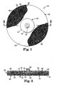
- FIG. 1 A preferred embodiment of a surface treating article 10 of the present invention is illustrated in Figure 1.
- the surface treating article 10 includes surface conditioning disc 30 having fastener 12 attached thereto.
- the fastener 12 is melt-bonded to the back of the surface conditioning disc.
- the preferred spin welding method for achieving a melt-bond between the fastener 12 and surface conditioning disc 30 is described below.
- Fastener 12 includes a generally planar base 14.
- the base 14 includes a first side 16 that is spin welded to the surface conditioning disc 30 so as to melt-bond the fastener 12 to the disc.
- the first side 16 of the fastener base is preferably smooth and planar so as to provide sufficient surface area to achieve the desired strength of the melt bond. It is also preferred that the base 14 of the fastener is circular. In one preferred embodiment, the base 14 of the fastener 12 has a diameter of approximately 3 cm (1.2 in), although larger and smaller fasteners are within the scope of the invention.
- second side 18 tapers toward the outer edge of the base 14. Extending from the center of the second side 18 is drive member 20.
- Drive member 20 is configured for attaching the surface treating article 10 to a desired power tool.
- the drive member 20 is a threaded stud which fits with a corresponding female threaded back-up pad (not illustrated).
- a suitable back-up pad is available commercially as a RolocTM disc pad from Minnesota Mining and Manufacturing Company, St. Paul, Minnesota.
- the fastener 12 may comprise any polymeric material that has the appropriate melt, flow, and adhesion characteristics to become securely melt-bonded to the surface treating article by an appropriate spin welding process.
- useful polymeric materials will be thermoplastic in nature.
- thermosetting polymeric. materials may be employed if they are only lightly crosslinked or have a stable intermediate or "B-stage" state and therefore can be caused to flow under heat and pressure.
- thermoplastic polymeric materials include polyamides, polyesters, copolyamides, copolyesters, polyimides, polysulfone, and polyolefins.
- An example of a suitable thermosetting polymeric material is a novolak molding powder.
- thermoplastics are preferred, and of the thermoplastics, polyamides are preferred, with poly(hexamethylene adipamide) (nylon 6,6) being most preferred.
- the polymeric material may optionally include colorants, fillers, process aids, and reinforcing agents.
- colorants include pigments and dyes.
- fillers include, glass bubbles or spheres, particulate calcium carbonate, mica, and the like.
- Process aids may be materials such as lithium stearate, zinc stearate, and fluoropolymer materials that are known to enhance the flow characteristics of molten polymeric materials.
- Reinforcing agents may include glass fiber, carbon fiber, and metal fiber, all at levels up to about 50% by weight.
- the drive button may be made by any process known to one skilled in the art of plastic article manufacture. These include but are not limited to injection molding, reaction injection molding, and conventional machining. Preferred is injection molding. A preferred drive button is disclosed in U.S. Patent No. 3,562,968, "Surface Treating Tool," Johnson et al.
- the surface treating article 10 has a nonwoven abrasive surface conditioning disc 30 as the abrasive component of the article. It is also possible for the surface treating article of the present invention to be a coated abrasive disc, a polishing pad, a brush, or similar surface treating element.
- the term "abrasive" must be considered relative to the targeted workpiece and the intended effect, and commonly-used abrasive particles may or may not be present in the surface treating element, as, for example, in a fine polishing operation.
- Surface treating elements have a working surface and backing surface. The driving button is attached centrally to the backing surface.
- the preferred surface treating article is a nonwoven abrasive surface conditioning disc 30, such as is commercially available from Minnesota Mining and Manufacturing Company, St. Paul, Minnesota, under the trade designation "SCOTCH-BRITE" A-CRS Surface Conditioning Disc.
- the working surface 31 of such discs preferably comprises a lofty nonwoven web 40 of nylon 6,6 staple fibers 42 that has been needle punched through a reinforcing woven nylon scrim backing 32.
- Preferably, about 40% of the staple fibers 42 of the web protrude through interstices 38 formed by the warp yarns 34 and fill yarns 36 of the woven scrim 32 to attach the nonwoven web 40 and the woven scrim 32 together.
- the needle tacked fibers which penetrate through the woven scrim 32 are illustrated as 44.
- the remaining fibers 42 remain on the working surface side of the surface conditioning disc 30.
- a preferred surface conditioning article is described in detail in U.S. Patent No. 3,688,453, "Abrasive Articles," Legacy et al.
- the melt-bond obtained by spin welding is primarily obtained by softening the first side 16 of fastener base 14.
- the softened material of the fastener is forced under pressure to penetrate at 22 into a plurality of the interstices 38 of the woven scrim 32. Because the linear speed caused by the rotation of the fastener 12 is greater at the outer diameter of the base 14, the frictional temperatures at the outer diameter are greatest. Accordingly, the material of the fastener is sufficiently softened at the outer diameter portion of the first side 16 of the fastener base 14. This allows the fastener material 22 at the outer portion of the base 14 to bond at least partially around the yarns 34, 36 of the woven scrim 32, and to at least partially penetrate the interstices 38 in the woven scrim.
- This material 22 upon hardening, provides a strong mechanical bond between the fastener 12 and the scrim 32. Additionally, the material of the woven scrim may soften during spin welding to melt bond with the fastener 12. At the center of the base 14, where rotation causes a smaller linear speed, the frictional heat is less, and the first side 16 of the fastener base may not sufficiently soften to obtain penetration of fastener material 22 into the interstices of the woven scrim 32.
- the woven scrim backing is an open weave.
- the woven scrim comprise at least 5 warp yarns per inch and 5 fill yarns per inch, and more preferably about 16 warp yarns and fill yarns per inch.
- the preferred yarns are at least 100 denier, and more preferably approximately 840 denier.
- a yarn may be one or more fibers that act as or are treated as one unit.
- a yarn may be continuous filament or "spun" (aligned and twisted) from staple into a unified bundle.
- a yarn may be multifilament (more than one continuous filament) or monofilament.
- the open area between the warp and weft fibers is preferably at least 5% of the total area of the scrim, and more preferable approximately 30%.
- the fastener 12 preferably has a 3 cm diameter base 14 and is injection molded from nylon 6,6 having up to 45% by weight reinforcing glass fibers.
- the scrim 32 preferably includes sixteen warp yarns 34 per inch and sixteen fill yarns 36 per inch.
- the yarns 34, 36 are preferably 840 denier multifilament nylon yarns.
- the scrim 32 preferably includes a PVC coating to maintain the weave.
- Non-woven web 40 comprises nylon 6,6 staple fibers 42 needle tacked to the scrim 32 such that approximately 40% of the fibers 44 extend through the interstices 38 of the woven scrim 30.
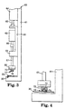
- FIG. 3 illustrates schematically an apparatus 60 for spin welding the fastener 12 and surface conditioning disc 30 together.
- Apparatus 60 includes a frame 61 to which a motor 62 and drive mechanism 64 are mounted.
- the drive mechanism 64 is an air cylinder.
- the motor 62 is mounted via a slidable frame 63 to allow the slidable frame 63 and motor 62 to be driven vertically by the rod 65 extending from the air cylinder 64.
- Rod 65 is attached to the slidable frame 63 so as to raise and lower the slidable frame in response to actuating the cylinder 64.
- Extending from the motor 62 is a first shaft 66.
- the first shaft is coupled to a second shaft 67.
- an optional flywheel 68 is mounted to the distal end of the second shaft 67. Also mounted at the distal end of the shaft is a fixture 70 for holding the fastener 12.
- the second shaft may optionally pass through bearing support 69 which extends from the slidable frame 63. It is thus seen that the motor 62 drives first shaft 66, second shaft 67, optional flywheel 68 and fixture 70; and that all of these components are raised and lowered together with slidable frame 63 in response to actuating the cylinder 64.
- Fixture 70 can be any suitable fixture that will hold the fastener 12 during the spin weld operation. Fixture 70 must grip the fastener 12 securely enough to avoid slippage of the fastener 12 within the fixture 70 when the fastener is spun against the surface conditioning disc 30. Fixture 70 should also provide for easy release of the fastener 12 after the spin weld process. Fixture 70 thus may include moveable elements for gripping and releasing the fastener 12 as is well known in the art. In the embodiment illustrated in Figure 4, the fixture 70 includes a fixture body 72 having a cavity 74 therein. The cavity is sized to receive the threaded stud 20 of the fastener. Cavity 74 may optionally be threaded for mating with the fastener threaded stud 20.
- cavity 74 may include moveable elements (not illustrated) for gripping and releasing the threaded stud 20.
- Fixture 70 optionally includes an o-ring 76.
- O-ring 76 engages with the second side 18 of the fastener base 14.
- O-ring 76 is particularly preferred when there are no moveable elements in the fixture 70 for grabbing and releasing the threaded stud 20. This helps eliminate slippage between the fastener 12 and fixture 70 during the spin welding.
- the face of the fixture 70 which comes into contact with the second side 18 of the fastener base can be rough or textured to minimize slippage between the fixture and the fastener during spin welding. Whatever such arrangement is used, care should be taken so as not to damage the threaded stud 20 or the fastener 12 during spin welding.
- the surface treating article 30 may be clamped or otherwise mechanically held to the frame 60 to keep the disc 30 from rotating during spin welding.
- Any suitable methods for loading the fastener 12 and surface treating disc 30 before spin welding and unloading after spin welding may be provided for and would not be expected to affect the spin weld itself or the strength of the melt-bond.
- a preferred method of spin welding the fastener 12 to the surface conditioning disc 30 is as follows.
- the spin weld method comprises the steps of holding stationary the surface conditioning disc 30, mounting the fastener 12 in a suitable fixture 70 to be driven by the spin weld apparatus 60, accelerating the fixture 70 and fastener 12 to the desired rotational speed, activating the drive mechanism 64 to move the first side 16 of the fastener base 14 into contact with back side 33 of the woven scrim 32, applying sufficient force between the fastener and scrim while the fastener is spinning to soften at least one of the fastener 12 and scrim 32, allowing the fixture 70 and fastener 12 motor 62 to stop rotation, maintaining force between the fastener and scrim while the softened material sufficiently hardens, and removing the fastener 12 from the fixture 70 and releasing the surface conditioning disc 30.
- Any commercially available spin welding apparatus 60 capable of obtaining the conditions described herein may be used, such as the PMA Spinweld 90 available from Powell, McGee Associates, Inc., of Shoreview, Minnesota.
- Another suitable apparatus includes an Allen-Bradley servo motor model number 1326AB-B410J-21 or model number 1326AS-B330H-21, with a 1394-AM04 axis module, all available from Allen-Bradley Company, Inc. located in Milwaukee, Wisconsin.
- the spin weld apparatus is operated in a mode that removes power from the motor 62 after the fastener and scrim are brought into contact under pressure, allowing the friction between the fastener and scrim to bring the rotating fastener to a stop.
- rotation of the fixture 70 and fastener 12 can be resistance stopped.
- the parameters found to affect the strength of the melt-bond between the fastener 12 and surface conditioning disc 30 are as follows. These parameters are provided for a spin weld apparatus 60 having a system inertia of approximately 40 ounce-inches 2 used to fasten the preferred embodiments of the fastener 12 and surface conditioning disc 30 described herein.
- the force that the cylinder 64 applies to the system is preferably between about 125 and 1257 lb. (10 to 100 psi for a 4 inch diameter cylinder), more preferably between about 188 and 628 lb. (15 to 50 psi), and most preferably between about 375 and 628 lb. (30 to 50 psi).
- the speed of the motor 64 is preferably from about 3300 to 5700 RPM.
- the spin time is preferably between about 0.28 seconds and 0.38 seconds.
- the spin time is a measurement of how long the motor 62 is maintained under power from the time the solenoid valve is signaled to apply air pressure for the cylinder to move the fixture 70 and fastener 12 towards the scrim (a travel distance of from approximately 1/8 inch to 13/16 inch), and ends with the command to remove power from the motor 62 after the fastener 12 contacts the scrim.
- a useful parameter for determining suitable bond strengths is the speed of the motor (RPM) multiplied by the spin time (seconds). It has been determined that this parameter should be above a desired minimum to obtain the desired bond strength. Increasing the parameter beyond the desired minimum shifts the failure mode from release of the melt-bond to breakage of the threaded stud.
- (RPM)x(spin time) be between about 1254 and 2166.
- the cylinder 64 should maintain the fastener 12 in contact with the scrim 32 with at least a minimum preferred force to obtain a desired melt-bonded force between the scrim and fastener, and that increasing force shifts the release mode from release of the melt bond to breakage of the threaded stud. Therefore, increasing the force to beyond the point at witch the release mode switches does not significantly increase the overall strength of the surface treating article.
- the preferred force for the preferred embodiments of the fasteners 12 and surface treating discs 30 described herein is from about 377 pounds to about 628 pounds.
- a number of surface treating articles 10 were made by spin welding nylon 6,6 fasteners 12 with 33% by weight glass fibers, having a 3 cm diameter base 14 to the specified surface conditioning disc 30.
- the spin weld apparatus used had a system inertia of approximately 40 ounce-inches 2 .
- a 2 inch diameter surface conditioning disc was held stationary.
- the motor 62 was accelerated to the specified RPM, and then the cylinder 64 was actuated with the indicated force to bring the fastener 12 into contact with the scrim 32 of the surface conditioning disc 30 (a travel distance of approximately 13/16 inch).
- the power to the motor was removed at the end of the indicated spin time.
- the spin time indicates the time from actuating the cylinder 64 until the power was removed after the fastener and scrim were brought into contact.
- the spin time thus includes the sum of the travel time before contacting the fastener and scrim and the time the motor was under power upon contacting the fastener and scrim. Friction between the fastener 12 and the scrim 32 then stops rotation of the fastener 12.
- Example 1 illustrates that for a given spin time and rotational speed, increasing cylinder pressure 64 beyond a desired minimum does not significantly increase the strength of the surface treating article.
- the fastener 12 was spin welded to a 2 inch diameter surface conditioning disc of the type available as A-Med surface conditioning discs from Minnesota Mining and Manufacturing Company, St. Paul, Minnesota.
- the spin time (as defined above) was 0.33 seconds.
- the spin weld speed was 4500 RPM.
- the force imparted by the cylinder 64 varied from 125 to 628 pounds. Tensile strength was determined by measuring the peak force observed in separating the melt-bonded fastener 12 from the surface conditioning disc 30.
- the failure mode changes from predominately spin weld release to predominately breakage of the threaded stud 20 from the base 14. Accordingly, at forces at or above 377 pounds, with the other parameters held constant, any increase in strength of the spin weld cannot be measured by this technique, and would not be expected to provide any improvement in overall strength of the surface treating article 10.
- Examples 2-4 demonstrate that after a minimum desired level of (spin time)x(RPM) is obtained, the failure mode changes from predominately release of the spin weld bond to predominately breakage of the threaded stud 20 from the base 14 of the fastener. Therefore, increased spin weld strength above the change-over point cannot be measured by this technique. Furthermore, for all other parameters held constant, increasing this parameter would not be expected to significantly increase the overall strength of the surface treating article. For examples 2-4, for values of (spin time)x(RPM) at or above 1254, failure mode is breakage of the threaded stud.
- the surface conditioning discs 30 were 2 inch diameter discs of the type available as A-VFN from Minnesota Mining and Manufacturing Company, St. Paul, Minnesota.
- the surface conditioning discs 30 were 2 inch diameter discs of the type available as A-MED from Minnesota Mining and Manufacturing Company, St. Paul, Minnesota.
- the surface conditioning discs 30 were 2 inch diameter discs of the type available as A-CRS from Minnesota Mining and Manufacturing Company, St. Paul, Minnesota.
- the force imparted by cylinder 64 was 628 pounds. Tensile strength was determined by measuring the peak force observed in separating the melt-bonded fastener 12 from the surface conditioning disc 30. The results for Examples 2-4 are presented in Tables 2-4, respectively.
- test results described above are intended solely to be illustrative, rather than predictive, and variations in the testing procedure can be expected to yield different results.
Landscapes
- Engineering & Computer Science (AREA)
- Mechanical Engineering (AREA)
- Physics & Mathematics (AREA)
- Fluid Mechanics (AREA)
- Manufacturing & Machinery (AREA)
- Lining Or Joining Of Plastics Or The Like (AREA)
- Polishing Bodies And Polishing Tools (AREA)
Applications Claiming Priority (3)
| Application Number | Priority Date | Filing Date | Title |
|---|---|---|---|
| US834268 | 1997-04-15 | ||
| US08/834,268 US5931729A (en) | 1997-04-15 | 1997-04-15 | Article made by spin welding a fastener thereto |
| PCT/US1997/014716 WO1998046413A1 (en) | 1997-04-15 | 1997-08-21 | Method for attaching a fastener to a surface treating article, and such an article having a fastener |
Publications (2)
| Publication Number | Publication Date |
|---|---|
| EP0975460A1 EP0975460A1 (en) | 2000-02-02 |
| EP0975460B1 true EP0975460B1 (en) | 2001-11-07 |
Family
ID=25266528
Family Applications (1)
| Application Number | Title | Priority Date | Filing Date |
|---|---|---|---|
| EP19970938495 Expired - Lifetime EP0975460B1 (en) | 1997-04-15 | 1997-08-21 | Method for attaching a fastener to a surface treating article, and such an article having a fastener |
Country Status (6)
| Country | Link |
|---|---|
| US (2) | US5931729A (enExample) |
| EP (1) | EP0975460B1 (enExample) |
| JP (1) | JP4318757B2 (enExample) |
| AU (1) | AU4080297A (enExample) |
| DE (1) | DE69708158T2 (enExample) |
| WO (1) | WO1998046413A1 (enExample) |
Families Citing this family (30)
| Publication number | Priority date | Publication date | Assignee | Title |
|---|---|---|---|---|
| GB9803604D0 (en) * | 1998-02-21 | 1998-04-15 | Merit Abrasives Europ Limited | Surface treatment |
| US6153035A (en) * | 1999-02-12 | 2000-11-28 | The Boeing Company | Method and apparatus for securing a thermoplastic insert within a sandwich panel |
| US6152814A (en) * | 1999-09-16 | 2000-11-28 | Rp Abrasives & Machine Co. Inc. | Expandable abrasive belt for use with inflatable tool |
| EP1276594B1 (en) * | 2000-04-18 | 2006-01-25 | 3M Innovative Properties Company | Method for attaching a fastener to a surface treating member, and such an article having a fastener |
| US6632130B1 (en) | 2000-05-23 | 2003-10-14 | Thomas Whiting | Abrade and cut disc |
| US6609951B1 (en) * | 2000-06-30 | 2003-08-26 | 3M Innovative Properties Company | Method of making a surface treating article |
| US6814824B2 (en) * | 2002-09-26 | 2004-11-09 | Sonics & Materials, Inc. | Method for vibration welding fabrics to substrates |
| DE102004013836A1 (de) * | 2004-03-16 | 2005-10-06 | Bielomatik Leuze Gmbh + Co.Kg | Verfahren zum Rotationsreibschweißen von Kunststoffteilen sowie Vorrichtung zur Durchführung des Verfahrens |
| US7121924B2 (en) * | 2004-04-20 | 2006-10-17 | 3M Innovative Properties Company | Abrasive articles, and methods of making and using the same |
| GB0418633D0 (en) * | 2004-08-20 | 2004-09-22 | 3M Innovative Properties Co | Method of making abrasive article |
| US8764517B2 (en) * | 2006-02-28 | 2014-07-01 | 3M Innovative Properties Company | Abrasive article and method of making the same |
| JP5448289B2 (ja) * | 2006-06-15 | 2014-03-19 | スリーエム イノベイティブ プロパティズ カンパニー | 研磨ディスク |
| DE102007003357A1 (de) * | 2007-01-17 | 2008-07-24 | Airbus Deutschland Gmbh | Verfahren zum Verbinden eines thermoplastischen Materials mit einem Faserverbundmaterial |
| US20080295947A1 (en) * | 2007-06-01 | 2008-12-04 | Bourbeau Alain | Method for ultrasonic welding and ultrasonic welding fastener and joining systems |
| CN102107397B (zh) | 2009-12-25 | 2015-02-04 | 3M新设资产公司 | 研磨砂轮的制造方法及研磨砂轮 |
| FR2954723B1 (fr) * | 2009-12-29 | 2012-04-20 | Saint Gobain Abrasives Inc | Article abrasif comprenant un espace creux entre ses faces avant et arriere, et procede de fabrication |
| BR112013031621B1 (pt) * | 2011-06-30 | 2021-03-09 | Saint-Gobain Abrasives, Inc. | artigo abrasivo e um método para sua fabricação |
| US20130225051A1 (en) * | 2012-02-27 | 2013-08-29 | Raymond Vankouwenberg | Abrasive pad assembly |
| WO2014176143A1 (en) * | 2013-04-22 | 2014-10-30 | Veerag Mehta | Toughening and flexibilizing thermoplastic and thermoset polymers |
| JP6185183B2 (ja) * | 2013-12-27 | 2017-08-23 | サンーゴバン アブレイシブズ,インコーポレイティド | 摩擦溶接により製造される不織布研磨材物品 |
| US10343260B2 (en) | 2014-02-14 | 2019-07-09 | 3M Innovative Properties Company | Abrasive article and method of using the same |
| TWI583730B (zh) | 2014-05-29 | 2017-05-21 | 聖高拜磨料有限公司 | 具有包含聚合物材料之核的磨料製品 |
| US9878489B2 (en) | 2014-12-18 | 2018-01-30 | GM Global Technology Operations LLC | Spin-welding of polymeric components having large surface area or non-complementary weld interfaces |
| EP3081434A1 (en) * | 2015-04-15 | 2016-10-19 | Autoneum Management AG | Engine cover arrangement |
| US20210146635A1 (en) * | 2017-09-27 | 2021-05-20 | Woodwelding Ag | Securing a second object to a first object |
| USD910396S1 (en) | 2018-09-24 | 2021-02-16 | 3M Innovative Properties Company | Attachment for a sanding device |
| CN115397617A (zh) | 2020-03-18 | 2022-11-25 | 3M创新有限公司 | 用于研磨盘的附接系统和方法 |
| DE102020128377A1 (de) * | 2020-10-28 | 2022-04-28 | Jobra Metall-GmbH | Verfahren zur Herstellung einer Schleifscheibenvorrichtung für ein Schleifgerät und Schleifscheibenvorrichtung |
| FR3139029A1 (fr) | 2022-08-25 | 2024-03-01 | Oberthur Fiduciaire Sas | Procédé d’authentification ou d’identification d’un document de sécurité |
| GB2700096A (en) * | 2023-12-15 | 2025-09-24 | Autex Industries Ltd | Fixing of pet panels to allow for recycling |
Family Cites Families (33)
| Publication number | Priority date | Publication date | Assignee | Title |
|---|---|---|---|---|
| NL173040B (nl) * | 1951-10-22 | Akerlund & Rausing Ab | Inrichting voor het vormen van een houder uit een stuk ruw gevormd karton of plano. | |
| US3362114A (en) * | 1964-11-04 | 1968-01-09 | Rexall Drug Chemical | Universal driving spindle and wheel assembly |
| US3468732A (en) * | 1966-08-19 | 1969-09-23 | Uniroyal Inc | Method of butt joining thermoplastic sheet material by a spin welding operation |
| US3580793A (en) * | 1966-08-19 | 1971-05-25 | Uniroyal Inc | Apparatus for welding thermoplastic sheet material |
| US3539436A (en) * | 1966-08-29 | 1970-11-10 | Int Knitlock Corp | Knitted product having a material-engaging surface |
| US3500592A (en) * | 1968-01-09 | 1970-03-17 | Robert A Harrist | Plastic hub and the application thereof to an abrasive wheel |
| US3562968A (en) * | 1969-03-12 | 1971-02-16 | Minnesota Mining & Mfg | Surface treating tool |
| US3653857A (en) * | 1970-03-20 | 1972-04-04 | Albert Field | Abrading implement |
| US3688453A (en) * | 1970-12-11 | 1972-09-05 | Minnesota Mining & Mfg | Abrasive articles |
| US3800483A (en) * | 1971-01-22 | 1974-04-02 | W Sherman | Method of making grinding wheel mounts |
| US4054425A (en) * | 1971-01-22 | 1977-10-18 | Sherman William F | Process of making a grinding wheel assembly |
| US3851357A (en) * | 1971-02-03 | 1974-12-03 | American Velcro Inc | Fastener |
| ZA726548B (en) * | 1971-10-02 | 1973-06-27 | Lucas Industries Ltd | Friction welding apparatus |
| US4075820A (en) * | 1976-07-28 | 1978-02-28 | Abbott Laboratories | Spin welding apparatus |
| GB2061183A (en) * | 1979-10-19 | 1981-05-13 | Tucker Fasteners Ltd | Friction welding |
| US4353761A (en) * | 1981-07-30 | 1982-10-12 | Boise Cascade Corporation | Method for spin bonding ends for composite containers |
| US4457795A (en) * | 1982-05-27 | 1984-07-03 | Baxter Travenol Laboratories, Inc. | Method and apparatus for spin welding soft, flexible thermoplastics |
| US4477307A (en) * | 1982-12-06 | 1984-10-16 | Illinois Tool Works Inc. | Friction welded fastener system |
| US4551189A (en) * | 1984-12-12 | 1985-11-05 | Illinois Tool Works Inc. | Friction welded fastener system |
| US4636124A (en) * | 1985-05-06 | 1987-01-13 | Illinois Tool Works Inc. | Adhesive friction weld fastener |
| US4599768A (en) * | 1985-05-13 | 1986-07-15 | Illinois Tool Works Inc. | Spin welded fastening assembly |
| JPS6328633A (ja) * | 1986-07-23 | 1988-02-06 | Nifco Inc | 樹脂製回転溶着部材 |
| JPS6328631A (ja) * | 1986-07-23 | 1988-02-06 | Nifco Inc | 樹脂製回転溶着部材 |
| JPS6328632A (ja) * | 1986-07-23 | 1988-02-06 | Nifco Inc | 樹脂製回転溶着部材 |
| US5064485A (en) * | 1990-04-23 | 1991-11-12 | Shell Oil Company | Method for the resilient spinwelding of thermoplastic articles |
| US5108539A (en) * | 1990-04-23 | 1992-04-28 | Shell Oil Company | Apparatus for the resilient spinwelding of thermoplastic articles |
| US5026445A (en) * | 1990-05-11 | 1991-06-25 | Branson Ultrasonics Corporation | Method and apparatus for producing carpeted panels |
| US5238521A (en) * | 1991-10-30 | 1993-08-24 | Signode Corporation | Apparatus for engaging thermoplastic strap in a friction-fusion welding system |
| DE4210066C1 (en) * | 1992-03-27 | 1993-06-09 | Mercedes-Benz Aktiengesellschaft, 7000 Stuttgart, De | Fabric clip mounting - has injection moulding appts. to shape plastics component and be bonded to fabric at defined location within assembly |
| US5306383A (en) * | 1992-10-30 | 1994-04-26 | Signode Corporation | Method and apparatus for producing a welded joint in thermoplastic strap with differential pressure |
| US5297366A (en) * | 1993-03-26 | 1994-03-29 | Huddleston Michael D | Self affixing sanding and buffing pads/system and apparatus |
| US5593120A (en) * | 1994-11-21 | 1997-01-14 | Minnesota Mining And Manufacturing Company | Quick-mounting fastening assembly |
| US5573844A (en) * | 1995-01-06 | 1996-11-12 | Minnesota Mining And Manufacturing Company | Conformable surface finishing article and method for manufacture of same |
-
1997
- 1997-04-15 US US08/834,268 patent/US5931729A/en not_active Expired - Lifetime
- 1997-08-21 JP JP54384998A patent/JP4318757B2/ja not_active Expired - Lifetime
- 1997-08-21 WO PCT/US1997/014716 patent/WO1998046413A1/en not_active Ceased
- 1997-08-21 AU AU40802/97A patent/AU4080297A/en not_active Abandoned
- 1997-08-21 DE DE69708158T patent/DE69708158T2/de not_active Expired - Lifetime
- 1997-08-21 EP EP19970938495 patent/EP0975460B1/en not_active Expired - Lifetime
-
1999
- 1999-03-24 US US09/275,344 patent/US6001202A/en not_active Expired - Lifetime
Also Published As
| Publication number | Publication date |
|---|---|
| WO1998046413A1 (en) | 1998-10-22 |
| JP4318757B2 (ja) | 2009-08-26 |
| US6001202A (en) | 1999-12-14 |
| DE69708158D1 (de) | 2001-12-13 |
| JP2001524039A (ja) | 2001-11-27 |
| AU4080297A (en) | 1998-11-11 |
| EP0975460A1 (en) | 2000-02-02 |
| US5931729A (en) | 1999-08-03 |
| DE69708158T2 (de) | 2002-07-11 |
Similar Documents
| Publication | Publication Date | Title |
|---|---|---|
| EP0975460B1 (en) | Method for attaching a fastener to a surface treating article, and such an article having a fastener | |
| EP0861137B1 (en) | Back-up pad for use with abrasive articles | |
| US5725423A (en) | Abrading apparatus | |
| US6579161B1 (en) | Abrasive article | |
| EP1037728B1 (en) | Surface treatment article having a quick release fastener | |
| AU2014370191B2 (en) | Nonwoven abrasive articles made by friction welding | |
| EP1276594B1 (en) | Method for attaching a fastener to a surface treating member, and such an article having a fastener | |
| US6988941B2 (en) | Engaging assembly for abrasive back-up pad | |
| AU652788B2 (en) | Attachment mechanism for nonwoven thermoformed articles | |
| CA2307794A1 (en) | Plate tool having quick-engaging element, provided with work surface | |
| US20030136508A1 (en) | Method of manufacturing a buffing pad | |
| JPH057547A (ja) | 靴拭いセパレートマツト |
Legal Events
| Date | Code | Title | Description |
|---|---|---|---|
| PUAI | Public reference made under article 153(3) epc to a published international application that has entered the european phase |
Free format text: ORIGINAL CODE: 0009012 |
|
| 17P | Request for examination filed |
Effective date: 19990917 |
|
| AK | Designated contracting states |
Kind code of ref document: A1 Designated state(s): DE FR GB |
|
| GRAG | Despatch of communication of intention to grant |
Free format text: ORIGINAL CODE: EPIDOS AGRA |
|
| 17Q | First examination report despatched |
Effective date: 20001004 |
|
| GRAG | Despatch of communication of intention to grant |
Free format text: ORIGINAL CODE: EPIDOS AGRA |
|
| GRAG | Despatch of communication of intention to grant |
Free format text: ORIGINAL CODE: EPIDOS AGRA |
|
| GRAH | Despatch of communication of intention to grant a patent |
Free format text: ORIGINAL CODE: EPIDOS IGRA |
|
| GRAH | Despatch of communication of intention to grant a patent |
Free format text: ORIGINAL CODE: EPIDOS IGRA |
|
| GRAA | (expected) grant |
Free format text: ORIGINAL CODE: 0009210 |
|
| AK | Designated contracting states |
Kind code of ref document: B1 Designated state(s): DE FR GB |
|
| REF | Corresponds to: |
Ref document number: 69708158 Country of ref document: DE Date of ref document: 20011213 |
|
| REG | Reference to a national code |
Ref country code: GB Ref legal event code: IF02 |
|
| PLBE | No opposition filed within time limit |
Free format text: ORIGINAL CODE: 0009261 |
|
| STAA | Information on the status of an ep patent application or granted ep patent |
Free format text: STATUS: NO OPPOSITION FILED WITHIN TIME LIMIT |
|
| 26N | No opposition filed | ||
| REG | Reference to a national code |
Ref country code: FR Ref legal event code: PLFP Year of fee payment: 20 |
|
| PGFP | Annual fee paid to national office [announced via postgrant information from national office to epo] |
Ref country code: GB Payment date: 20160817 Year of fee payment: 20 Ref country code: DE Payment date: 20160816 Year of fee payment: 20 |
|
| PGFP | Annual fee paid to national office [announced via postgrant information from national office to epo] |
Ref country code: FR Payment date: 20160712 Year of fee payment: 20 |
|
| REG | Reference to a national code |
Ref country code: DE Ref legal event code: R071 Ref document number: 69708158 Country of ref document: DE |
|
| REG | Reference to a national code |
Ref country code: GB Ref legal event code: PE20 Expiry date: 20170820 |
|
| PG25 | Lapsed in a contracting state [announced via postgrant information from national office to epo] |
Ref country code: GB Free format text: LAPSE BECAUSE OF EXPIRATION OF PROTECTION Effective date: 20170820 |