EP0975112B1 - Méthode de synchronisation d'éléments externes à un dispositif de commutation par des sorties d'horloge - Google Patents
Méthode de synchronisation d'éléments externes à un dispositif de commutation par des sorties d'horloge Download PDFInfo
- Publication number
- EP0975112B1 EP0975112B1 EP99113313A EP99113313A EP0975112B1 EP 0975112 B1 EP0975112 B1 EP 0975112B1 EP 99113313 A EP99113313 A EP 99113313A EP 99113313 A EP99113313 A EP 99113313A EP 0975112 B1 EP0975112 B1 EP 0975112B1
- Authority
- EP
- European Patent Office
- Prior art keywords
- clock
- switching device
- clock outputs
- type
- outputs
- Prior art date
- Legal status (The legal status is an assumption and is not a legal conclusion. Google has not performed a legal analysis and makes no representation as to the accuracy of the status listed.)
- Expired - Lifetime
Links
- 230000001419 dependent effect Effects 0.000 description 3
- 230000000712 assembly Effects 0.000 description 2
- 238000000429 assembly Methods 0.000 description 2
- 230000005540 biological transmission Effects 0.000 description 2
- 210000000056 organ Anatomy 0.000 description 2
- 230000001360 synchronised effect Effects 0.000 description 2
- 150000001875 compounds Chemical class 0.000 description 1
- 230000008878 coupling Effects 0.000 description 1
- 238000010168 coupling process Methods 0.000 description 1
- 238000005859 coupling reaction Methods 0.000 description 1
- 230000009849 deactivation Effects 0.000 description 1
- 238000011156 evaluation Methods 0.000 description 1
- 230000011664 signaling Effects 0.000 description 1
Images
Classifications
-
- H—ELECTRICITY
- H04—ELECTRIC COMMUNICATION TECHNIQUE
- H04J—MULTIPLEX COMMUNICATION
- H04J3/00—Time-division multiplex systems
- H04J3/02—Details
- H04J3/06—Synchronising arrangements
- H04J3/0635—Clock or time synchronisation in a network
- H04J3/0685—Clock or time synchronisation in a node; Intranode synchronisation
Definitions
- the invention relates to an arrangement for the synchronization of external components of a switching device.
- Existing switching devices in particular private branch exchanges, have clock outputs which are always permanently switched.
- the supply cable or the corresponding connector assembly must be pulled.
- each switch may act as a master or slave clock.
- Each switch has a mechanism for selecting the clock with the highest quality or quality.
- clock outputs thereafter, which type of external components can be connected.
- the control of the clock outputs is dependent on their function, in particular by the central control of the switching device. All types of clock outputs can be manually switched, for example via a service program.
- For some kind of clock outputs is an automatic on or off possible, so that no removal of cables or connection assemblies is necessary for deactivation.
- an automatic control switching on or off means a more accurate and reliable operation.
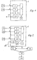
- FIG. 1 shows the connection of external components to a switching device via clock outputs
- Figure 2 shows a system network of switching equipment with external components connected.
- Figure 1 shows schematically a switching device 1, e.g. a private branch exchange, with a plurality of external component connections 7, 10, for example external multiplexers, antennas, with a plurality of external component connections 4, 20, for example subscriber terminals or trunk lines, e.g. 19, a coupling network 5 and a central controller 6.
- External components 7, 10 are connected via clock outputs 8, 9 to terminal assemblies - here connection modules 2 and 3 - connected. For the connection of external components several connections per switching device or connection module are possible.
- a connection module tells the central controller 6 that there are clock outputs on it as well as which type of Clock outputs.
- the clock outputs are to be distinguished according to which type of external components 7, 10 are connected. At least two types of external components and thus also two types of clock outputs are distinguished here. All types of clock outputs are manually z. B. be switchable via a service program. Furthermore, for a certain type of clock outputs, which depends on their function, an automatic control, that is, in particular a connection or disconnection from the central controller 6 of the switching device 1, for example, by a corresponding system software.
- the type of clock output is defined in each case by a specific connection element type of connectable external components. Because of this type of terminal organ of the clock output, the central controller 6 determines whether automatic control (on or off) is required for this clock output or not. The automatic switching on and off of the clock outputs is initiated by the central controller 6. This controller determines when to enable or disable the clock outputs.
- the external clock generator 15 connected to the switching device 1 is given precedence as the clock standard for the system network, irrespective of whether the switching devices 11, 12, 13 or 14 have other clock sources for synchronization, such as the office clock DIVO (digital mediation, location) - management.
- DIVO digital mediation, location
- connection module In order for an external clock generator 15 connected to a connection module - here 16 - to be able to be recognized by the central controller 6, the connection module must be designed to be correspondingly configurable, eg by a service program. It is determined that it is an external clock generator due to the terminal organ type of the clock input 18. Once the connector assembly 16 determines that the external clock generator 15 is providing a clock, it reports this to the central controller. The controller 6 is an evaluation logic 17 associated with the selection of the synchronization clock. If the external clock generator 15 supplies a clock, it is given priority as a clock standard before, for example, a DIVO connection.
- the further switching devices 11, 12, 13, 14 is in particular via a signaling channel in the compound line at the output 19, for example, the D channel in ISDN, communicated that the external clock generator 15 is available as a clock standard for synchronization purposes.
- the external clock generator 15 is now irrespective of which of the switching devices it is connected, the priority as clock normal for synchronization for the other switching equipment of the network granted so that all switching devices synchronize to the switching device with external clock connected, even if they have their own Have DIVO connection.
- External components can thus be easily synchronized to a very accurate clock standard of the system network.
Landscapes
- Engineering & Computer Science (AREA)
- Computer Networks & Wireless Communication (AREA)
- Signal Processing (AREA)
- Synchronisation In Digital Transmission Systems (AREA)
- Use Of Switch Circuits For Exchanges And Methods Of Control Of Multiplex Exchanges (AREA)
- Electric Clocks (AREA)
Claims (7)
- Dispositif de synchronisation d'éléments (7, 10) externes d'un dispositif (1) de commutation par ses sorties (8, 9) d'horloge, caractérisé par des sorties (8) d'horloge au moins d'un type qui, en fonction de son fonctionnement, peut être branché ou débranché par le dispositif (1) de commutation.
- Dispositif suivant la revendication 1, comprenant des sorties (9, 9) d'horloge d'un deuxième type, les deux types pouvant être commutés manuellement et un type de sorties (8) d'horloge pouvant être branché et débranché automatiquement par une commande (6) centrale du dispositif (1) de commutation.
- Dispositif suivant la revendication 1 ou 2, caractérisé en ce que les sorties (8) d'horloge d'un type peuvent être activées lorsque le dispositif (1) de commutation travaille comme maître d'horloge dans une installation complexe.
- Dispositif suivant la revendication 1 ou 2, caractérisé en ce que les sorties (8) d'horloge d'un type peuvent être déactivées lorsqu'elles opèrent comme esclave d'horloge dans le fonctionnement stand-alone ou dans une installation complexe.
- Dispositif suivant l'une des revendications 1 à 4, caractérisé en ce que les sorties (8, 9) d'horloge sont prévues sur un module (2,3) de connexion du dispositif de commutation, dans lequel, lors de la mise en fonctionnement d'un module (3) de connexion, une commande (6) centrale fait part au dispositif (1) de commutation que des sorties d'horloges y sont prévues et également du type de sorties d'horloge.
- Dispositif suivant l'une des revendications 1 à 5, caractérisé en ce que le type d'une sortie d'horloge dépend de son type d'organe de connexion, qui dépend à son tour du type des éléments (7, 10) externes raccordés.
- Dispositif suivant l'une des revendications 1 à 6, caractérisé en ce que, pour des éléments (7) externes qui dépendent de la synchronisation du dispositif (1) de commutation d'une installation complexe, il est prévu une commande automatique de la sortie (8) d'horloge, qui peut lui être raccordé.
Applications Claiming Priority (2)
| Application Number | Priority Date | Filing Date | Title |
|---|---|---|---|
| DE19833282A DE19833282A1 (de) | 1998-07-24 | 1998-07-24 | Verfahren zur Synchronisation externer Komponenten einer Vermittlungseinrichtung über Taktausgänge |
| DE19833282 | 1998-07-24 |
Publications (3)
| Publication Number | Publication Date |
|---|---|
| EP0975112A2 EP0975112A2 (fr) | 2000-01-26 |
| EP0975112A3 EP0975112A3 (fr) | 2004-05-12 |
| EP0975112B1 true EP0975112B1 (fr) | 2007-09-12 |
Family
ID=7875129
Family Applications (1)
| Application Number | Title | Priority Date | Filing Date |
|---|---|---|---|
| EP99113313A Expired - Lifetime EP0975112B1 (fr) | 1998-07-24 | 1999-07-09 | Méthode de synchronisation d'éléments externes à un dispositif de commutation par des sorties d'horloge |
Country Status (3)
| Country | Link |
|---|---|
| EP (1) | EP0975112B1 (fr) |
| AT (1) | ATE373261T1 (fr) |
| DE (2) | DE19833282A1 (fr) |
Family Cites Families (4)
| Publication number | Priority date | Publication date | Assignee | Title |
|---|---|---|---|---|
| ATE115342T1 (de) * | 1991-09-02 | 1994-12-15 | Siemens Ag | Verfahren und vorrichtung zur synchronisation einer takteinrichtung eines fernmeldevermittlungssystems. |
| DE4131061C1 (en) * | 1991-09-18 | 1992-09-10 | Siemens Ag, 8000 Muenchen, De | Switching procedure for external reference pulse signal in telephone exchange - conducting external reference signals to module delivering reference pulse series for synchronising central pulse generator or clock |
| US5577075A (en) * | 1991-09-26 | 1996-11-19 | Ipc Information Systems, Inc. | Distributed clocking system |
| DE4227283C1 (de) * | 1992-08-18 | 1993-12-16 | Siemens Ag | Verfahren zum automatischen Ankoppeln eines Kommunikationssysstems an einen externen Referenztakt |
-
1998
- 1998-07-24 DE DE19833282A patent/DE19833282A1/de not_active Withdrawn
-
1999
- 1999-07-09 AT AT99113313T patent/ATE373261T1/de not_active IP Right Cessation
- 1999-07-09 DE DE59914495T patent/DE59914495D1/de not_active Expired - Lifetime
- 1999-07-09 EP EP99113313A patent/EP0975112B1/fr not_active Expired - Lifetime
Non-Patent Citations (1)
| Title |
|---|
| None * |
Also Published As
| Publication number | Publication date |
|---|---|
| DE59914495D1 (de) | 2007-10-25 |
| ATE373261T1 (de) | 2007-09-15 |
| DE19833282A1 (de) | 2000-01-27 |
| EP0975112A2 (fr) | 2000-01-26 |
| EP0975112A3 (fr) | 2004-05-12 |
Similar Documents
| Publication | Publication Date | Title |
|---|---|---|
| DE69129258T2 (de) | Vermittlungssystem von optischen Übertragungsleitungen zum Störungsschutz | |
| EP3955529B1 (fr) | Unité pour un système de bus, système de bus maître-esclave doté d'une pluralité d'unités et procédé d'adressage des unités d'un système de bus | |
| EP1757112B1 (fr) | Dispositif et procede de transmission de donnees avec risque de defaillance limite | |
| EP1356619B1 (fr) | Procede et circuit electro-optique destines a la protection de ligne dans un lien de transmission de donnees wdm | |
| DE69130199T2 (de) | Teilnehmerschnittstelle für ein Kommunikationsendgerät mit optischen Fasern | |
| DE19615174B4 (de) | Vorrichtung zur Signalübertragung in einem synchronen digitalen hierarchischen Netzwerk | |
| EP0975112B1 (fr) | Méthode de synchronisation d'éléments externes à un dispositif de commutation par des sorties d'horloge | |
| EP0241011B1 (fr) | Dispositif pour commuter des signaux de télévision en couleurs | |
| EP1695158B1 (fr) | Dispositif de transmission de donnees a securite intrinseque | |
| DE4306032C2 (de) | Schaltungsanordnung zum redundanten Aufbau in Kommunikationssystemen | |
| EP1151569B1 (fr) | Dispositif multiplexeur a insertion-extraction et systeme de transmission optique a multiplexage par repartition en longueur d'onde (wdm) | |
| DE60034412T2 (de) | Kommunikationssystem | |
| DE102008037610A1 (de) | Vorrichtung und Verfahren zur wahlweisen Umschaltung zweier Master für zugeordnete Slaves | |
| DE4038749C1 (en) | Subscriber peripheral circuit for ISDN - has coupling device to connect one of subscriber peripherals to digital network line | |
| EP0975113B1 (fr) | Méthode de synchronisation de dispositifs de commutation fonctionnant en interconnection | |
| DE4139265C2 (de) | Telekommunikations-Datenzugriffsgerät | |
| EP1252791B1 (fr) | Repartiteur optique | |
| EP0549862B1 (fr) | Réseau de transmissions optique | |
| DE4122276A1 (de) | Digitales kommunikationssystem | |
| DE102010005989B4 (de) | Verfahren zur Datenübertragung in zeitgesteuerten Kommunikationssystemen und zeitgesteuertes Kommunikationssystem | |
| DE69832080T2 (de) | Modulares digitales telefonsystem and verfahren mit einer universalen telefonanlage | |
| DE69430737T2 (de) | Schalteinrichtung | |
| DE19623480C1 (de) | Verfahren zur Generierung eines zur Steuerung einer Datenausgabe verwendbaren Ausgabetaktsignals in Abhängigkeit von einem von mehreren Eingabetaktsignalen | |
| DE3121774C2 (fr) | ||
| EP4300898A2 (fr) | Machine à vide |
Legal Events
| Date | Code | Title | Description |
|---|---|---|---|
| PUAI | Public reference made under article 153(3) epc to a published international application that has entered the european phase |
Free format text: ORIGINAL CODE: 0009012 |
|
| AK | Designated contracting states |
Kind code of ref document: A2 Designated state(s): AT BE CH CY DE DK ES FI FR GB GR IE IT LI LU MC NL PT SE |
|
| AX | Request for extension of the european patent |
Free format text: AL;LT;LV;MK;RO;SI |
|
| RAP1 | Party data changed (applicant data changed or rights of an application transferred) |
Owner name: TENOVIS GMBH & CO. KG |
|
| PUAL | Search report despatched |
Free format text: ORIGINAL CODE: 0009013 |
|
| AK | Designated contracting states |
Kind code of ref document: A3 Designated state(s): AT BE CH CY DE DK ES FI FR GB GR IE IT LI LU MC NL PT SE |
|
| AX | Request for extension of the european patent |
Extension state: AL LT LV MK RO SI |
|
| RIC1 | Information provided on ipc code assigned before grant |
Ipc: 7H 04Q 11/04 B Ipc: 7H 04J 3/06 B Ipc: 7G 06F 1/10 A |
|
| AKX | Designation fees paid | ||
| 17P | Request for examination filed |
Effective date: 20041210 |
|
| RBV | Designated contracting states (corrected) |
Designated state(s): AT BE CH CY DE DK ES FI FR GB GR IE IT LI LU MC NL PT SE |
|
| REG | Reference to a national code |
Ref country code: DE Ref legal event code: 8566 |
|
| 17Q | First examination report despatched |
Effective date: 20050329 |
|
| GRAP | Despatch of communication of intention to grant a patent |
Free format text: ORIGINAL CODE: EPIDOSNIGR1 |
|
| GRAS | Grant fee paid |
Free format text: ORIGINAL CODE: EPIDOSNIGR3 |
|
| GRAA | (expected) grant |
Free format text: ORIGINAL CODE: 0009210 |
|
| AK | Designated contracting states |
Kind code of ref document: B1 Designated state(s): AT BE CH CY DE DK ES FI FR GB GR IE IT LI LU MC NL PT SE |
|
| REG | Reference to a national code |
Ref country code: GB Ref legal event code: FG4D Free format text: NOT ENGLISH |
|
| REG | Reference to a national code |
Ref country code: CH Ref legal event code: EP |
|
| REF | Corresponds to: |
Ref document number: 59914495 Country of ref document: DE Date of ref document: 20071025 Kind code of ref document: P |
|
| REG | Reference to a national code |
Ref country code: IE Ref legal event code: FG4D Free format text: LANGUAGE OF EP DOCUMENT: GERMAN |
|
| GBT | Gb: translation of ep patent filed (gb section 77(6)(a)/1977) |
Effective date: 20071121 |
|
| PG25 | Lapsed in a contracting state [announced via postgrant information from national office to epo] |
Ref country code: FI Free format text: LAPSE BECAUSE OF FAILURE TO SUBMIT A TRANSLATION OF THE DESCRIPTION OR TO PAY THE FEE WITHIN THE PRESCRIBED TIME-LIMIT Effective date: 20070912 |
|
| NLV1 | Nl: lapsed or annulled due to failure to fulfill the requirements of art. 29p and 29m of the patents act | ||
| ET | Fr: translation filed | ||
| PG25 | Lapsed in a contracting state [announced via postgrant information from national office to epo] |
Ref country code: NL Free format text: LAPSE BECAUSE OF FAILURE TO SUBMIT A TRANSLATION OF THE DESCRIPTION OR TO PAY THE FEE WITHIN THE PRESCRIBED TIME-LIMIT Effective date: 20070912 Ref country code: GR Free format text: LAPSE BECAUSE OF FAILURE TO SUBMIT A TRANSLATION OF THE DESCRIPTION OR TO PAY THE FEE WITHIN THE PRESCRIBED TIME-LIMIT Effective date: 20071213 Ref country code: ES Free format text: LAPSE BECAUSE OF FAILURE TO SUBMIT A TRANSLATION OF THE DESCRIPTION OR TO PAY THE FEE WITHIN THE PRESCRIBED TIME-LIMIT Effective date: 20071223 |
|
| REG | Reference to a national code |
Ref country code: IE Ref legal event code: FD4D |
|
| PG25 | Lapsed in a contracting state [announced via postgrant information from national office to epo] |
Ref country code: PT Free format text: LAPSE BECAUSE OF FAILURE TO SUBMIT A TRANSLATION OF THE DESCRIPTION OR TO PAY THE FEE WITHIN THE PRESCRIBED TIME-LIMIT Effective date: 20080212 |
|
| PG25 | Lapsed in a contracting state [announced via postgrant information from national office to epo] |
Ref country code: SE Free format text: LAPSE BECAUSE OF FAILURE TO SUBMIT A TRANSLATION OF THE DESCRIPTION OR TO PAY THE FEE WITHIN THE PRESCRIBED TIME-LIMIT Effective date: 20071212 |
|
| PLBE | No opposition filed within time limit |
Free format text: ORIGINAL CODE: 0009261 |
|
| STAA | Information on the status of an ep patent application or granted ep patent |
Free format text: STATUS: NO OPPOSITION FILED WITHIN TIME LIMIT |
|
| 26N | No opposition filed |
Effective date: 20080613 |
|
| PG25 | Lapsed in a contracting state [announced via postgrant information from national office to epo] |
Ref country code: IE Free format text: LAPSE BECAUSE OF FAILURE TO SUBMIT A TRANSLATION OF THE DESCRIPTION OR TO PAY THE FEE WITHIN THE PRESCRIBED TIME-LIMIT Effective date: 20070912 |
|
| REG | Reference to a national code |
Ref country code: CH Ref legal event code: PL |
|
| PG25 | Lapsed in a contracting state [announced via postgrant information from national office to epo] |
Ref country code: MC Free format text: LAPSE BECAUSE OF NON-PAYMENT OF DUE FEES Effective date: 20080731 |
|
| PG25 | Lapsed in a contracting state [announced via postgrant information from national office to epo] |
Ref country code: LI Free format text: LAPSE BECAUSE OF NON-PAYMENT OF DUE FEES Effective date: 20080731 Ref country code: CH Free format text: LAPSE BECAUSE OF NON-PAYMENT OF DUE FEES Effective date: 20080731 |
|
| PG25 | Lapsed in a contracting state [announced via postgrant information from national office to epo] |
Ref country code: CY Free format text: LAPSE BECAUSE OF FAILURE TO SUBMIT A TRANSLATION OF THE DESCRIPTION OR TO PAY THE FEE WITHIN THE PRESCRIBED TIME-LIMIT Effective date: 20070912 |
|
| PG25 | Lapsed in a contracting state [announced via postgrant information from national office to epo] |
Ref country code: AT Free format text: LAPSE BECAUSE OF NON-PAYMENT OF DUE FEES Effective date: 20080709 |
|
| PG25 | Lapsed in a contracting state [announced via postgrant information from national office to epo] |
Ref country code: DK Free format text: LAPSE BECAUSE OF FAILURE TO SUBMIT A TRANSLATION OF THE DESCRIPTION OR TO PAY THE FEE WITHIN THE PRESCRIBED TIME-LIMIT Effective date: 20070912 |
|
| PG25 | Lapsed in a contracting state [announced via postgrant information from national office to epo] |
Ref country code: LU Free format text: LAPSE BECAUSE OF NON-PAYMENT OF DUE FEES Effective date: 20080709 |
|
| PG25 | Lapsed in a contracting state [announced via postgrant information from national office to epo] |
Ref country code: BE Free format text: LAPSE BECAUSE OF NON-PAYMENT OF DUE FEES Effective date: 20080731 |
|
| PGFP | Annual fee paid to national office [announced via postgrant information from national office to epo] |
Ref country code: FR Payment date: 20100802 Year of fee payment: 12 Ref country code: DE Payment date: 20100726 Year of fee payment: 12 |
|
| PGFP | Annual fee paid to national office [announced via postgrant information from national office to epo] |
Ref country code: GB Payment date: 20100726 Year of fee payment: 12 |
|
| PG25 | Lapsed in a contracting state [announced via postgrant information from national office to epo] |
Ref country code: IT Free format text: LAPSE BECAUSE OF NON-PAYMENT OF DUE FEES Effective date: 20080731 |
|
| GBPC | Gb: european patent ceased through non-payment of renewal fee |
Effective date: 20110709 |
|
| REG | Reference to a national code |
Ref country code: FR Ref legal event code: ST Effective date: 20120330 |
|
| PG25 | Lapsed in a contracting state [announced via postgrant information from national office to epo] |
Ref country code: DE Free format text: LAPSE BECAUSE OF NON-PAYMENT OF DUE FEES Effective date: 20120201 Ref country code: FR Free format text: LAPSE BECAUSE OF NON-PAYMENT OF DUE FEES Effective date: 20110801 |
|
| REG | Reference to a national code |
Ref country code: DE Ref legal event code: R119 Ref document number: 59914495 Country of ref document: DE Effective date: 20120201 |
|
| PG25 | Lapsed in a contracting state [announced via postgrant information from national office to epo] |
Ref country code: GB Free format text: LAPSE BECAUSE OF NON-PAYMENT OF DUE FEES Effective date: 20110709 |