EP0974015B1 - Aktives flüssigkeitslager - Google Patents
Aktives flüssigkeitslager Download PDFInfo
- Publication number
- EP0974015B1 EP0974015B1 EP98915315A EP98915315A EP0974015B1 EP 0974015 B1 EP0974015 B1 EP 0974015B1 EP 98915315 A EP98915315 A EP 98915315A EP 98915315 A EP98915315 A EP 98915315A EP 0974015 B1 EP0974015 B1 EP 0974015B1
- Authority
- EP
- European Patent Office
- Prior art keywords
- fluid
- piston
- active
- mounting
- active fluid
- Prior art date
- Legal status (The legal status is an assumption and is not a legal conclusion. Google has not performed a legal analysis and makes no representation as to the accuracy of the status listed.)
- Expired - Lifetime
Links
- 239000012530 fluid Substances 0.000 title claims description 284
- 238000005086 pumping Methods 0.000 claims description 16
- 230000003068 static effect Effects 0.000 claims description 15
- 230000008878 coupling Effects 0.000 claims description 3
- 238000010168 coupling process Methods 0.000 claims description 3
- 238000005859 coupling reaction Methods 0.000 claims description 3
- 230000002452 interceptive effect Effects 0.000 claims description 3
- 230000001939 inductive effect Effects 0.000 claims description 2
- 230000001747 exhibiting effect Effects 0.000 claims 1
- 229920001971 elastomer Polymers 0.000 description 21
- 239000000806 elastomer Substances 0.000 description 21
- 230000004907 flux Effects 0.000 description 11
- 239000000463 material Substances 0.000 description 11
- 230000008901 benefit Effects 0.000 description 10
- RYGMFSIKBFXOCR-UHFFFAOYSA-N Copper Chemical compound [Cu] RYGMFSIKBFXOCR-UHFFFAOYSA-N 0.000 description 8
- 229910000831 Steel Inorganic materials 0.000 description 7
- 229910052782 aluminium Inorganic materials 0.000 description 7
- XAGFODPZIPBFFR-UHFFFAOYSA-N aluminium Chemical compound [Al] XAGFODPZIPBFFR-UHFFFAOYSA-N 0.000 description 7
- 238000005192 partition Methods 0.000 description 7
- 239000010959 steel Substances 0.000 description 7
- 238000009419 refurbishment Methods 0.000 description 6
- 229910052802 copper Inorganic materials 0.000 description 5
- 239000010949 copper Substances 0.000 description 5
- 238000006073 displacement reaction Methods 0.000 description 5
- 230000005540 biological transmission Effects 0.000 description 4
- 230000000670 limiting effect Effects 0.000 description 4
- 230000035699 permeability Effects 0.000 description 4
- 229920003051 synthetic elastomer Polymers 0.000 description 4
- 230000000694 effects Effects 0.000 description 3
- 230000006870 function Effects 0.000 description 3
- 238000012986 modification Methods 0.000 description 3
- 230000004048 modification Effects 0.000 description 3
- 229920003052 natural elastomer Polymers 0.000 description 3
- 229920001194 natural rubber Polymers 0.000 description 3
- 239000004033 plastic Substances 0.000 description 3
- 229920001296 polysiloxane Polymers 0.000 description 3
- 238000005476 soldering Methods 0.000 description 3
- IJGRMHOSHXDMSA-UHFFFAOYSA-N Atomic nitrogen Chemical compound N#N IJGRMHOSHXDMSA-UHFFFAOYSA-N 0.000 description 2
- 229910001369 Brass Inorganic materials 0.000 description 2
- 244000043261 Hevea brasiliensis Species 0.000 description 2
- 230000004075 alteration Effects 0.000 description 2
- 239000010951 brass Substances 0.000 description 2
- 230000008859 change Effects 0.000 description 2
- 230000006835 compression Effects 0.000 description 2
- 238000007906 compression Methods 0.000 description 2
- 238000010276 construction Methods 0.000 description 2
- 238000013461 design Methods 0.000 description 2
- 239000007789 gas Substances 0.000 description 2
- 238000002955 isolation Methods 0.000 description 2
- 229910052751 metal Inorganic materials 0.000 description 2
- 239000002184 metal Substances 0.000 description 2
- 238000000034 method Methods 0.000 description 2
- 239000000203 mixture Substances 0.000 description 2
- 230000003534 oscillatory effect Effects 0.000 description 2
- 239000005061 synthetic rubber Substances 0.000 description 2
- 238000012360 testing method Methods 0.000 description 2
- 230000001052 transient effect Effects 0.000 description 2
- WFKWXMTUELFFGS-UHFFFAOYSA-N tungsten Chemical compound [W] WFKWXMTUELFFGS-UHFFFAOYSA-N 0.000 description 2
- 229910052721 tungsten Inorganic materials 0.000 description 2
- 239000010937 tungsten Substances 0.000 description 2
- RYXPMWYHEBGTRV-UHFFFAOYSA-N Omeprazole sodium Chemical compound [Na+].N=1C2=CC(OC)=CC=C2[N-]C=1S(=O)CC1=NC=C(C)C(OC)=C1C RYXPMWYHEBGTRV-UHFFFAOYSA-N 0.000 description 1
- 239000004721 Polyphenylene oxide Substances 0.000 description 1
- 239000006096 absorbing agent Substances 0.000 description 1
- 230000009471 action Effects 0.000 description 1
- 230000006978 adaptation Effects 0.000 description 1
- 230000003321 amplification Effects 0.000 description 1
- 230000003190 augmentative effect Effects 0.000 description 1
- DMFGNRRURHSENX-UHFFFAOYSA-N beryllium copper Chemical compound [Be].[Cu] DMFGNRRURHSENX-UHFFFAOYSA-N 0.000 description 1
- ZDVYABSQRRRIOJ-UHFFFAOYSA-N boron;iron Chemical compound [Fe]#B ZDVYABSQRRRIOJ-UHFFFAOYSA-N 0.000 description 1
- 230000005465 channeling Effects 0.000 description 1
- 238000013016 damping Methods 0.000 description 1
- 230000001419 dependent effect Effects 0.000 description 1
- 238000005265 energy consumption Methods 0.000 description 1
- 239000010720 hydraulic oil Substances 0.000 description 1
- 238000003780 insertion Methods 0.000 description 1
- 230000037431 insertion Effects 0.000 description 1
- 238000009434 installation Methods 0.000 description 1
- 230000003993 interaction Effects 0.000 description 1
- 238000011835 investigation Methods 0.000 description 1
- 239000007788 liquid Substances 0.000 description 1
- 229910052757 nitrogen Inorganic materials 0.000 description 1
- 238000003199 nucleic acid amplification method Methods 0.000 description 1
- 230000010355 oscillation Effects 0.000 description 1
- 238000013021 overheating Methods 0.000 description 1
- 230000036961 partial effect Effects 0.000 description 1
- 229920000570 polyether Polymers 0.000 description 1
- 238000004382 potting Methods 0.000 description 1
- 230000008569 process Effects 0.000 description 1
- 230000002829 reductive effect Effects 0.000 description 1
- 230000000717 retained effect Effects 0.000 description 1
- 238000005096 rolling process Methods 0.000 description 1
- 229920002379 silicone rubber Polymers 0.000 description 1
- 125000006850 spacer group Chemical group 0.000 description 1
- 229910001220 stainless steel Inorganic materials 0.000 description 1
- 239000010935 stainless steel Substances 0.000 description 1
- 238000012546 transfer Methods 0.000 description 1
Images



Classifications
-
- F—MECHANICAL ENGINEERING; LIGHTING; HEATING; WEAPONS; BLASTING
- F16—ENGINEERING ELEMENTS AND UNITS; GENERAL MEASURES FOR PRODUCING AND MAINTAINING EFFECTIVE FUNCTIONING OF MACHINES OR INSTALLATIONS; THERMAL INSULATION IN GENERAL
- F16F—SPRINGS; SHOCK-ABSORBERS; MEANS FOR DAMPING VIBRATION
- F16F13/00—Units comprising springs of the non-fluid type as well as vibration-dampers, shock-absorbers, or fluid springs
- F16F13/04—Units comprising springs of the non-fluid type as well as vibration-dampers, shock-absorbers, or fluid springs comprising both a plastics spring and a damper, e.g. a friction damper
- F16F13/06—Units comprising springs of the non-fluid type as well as vibration-dampers, shock-absorbers, or fluid springs comprising both a plastics spring and a damper, e.g. a friction damper the damper being a fluid damper, e.g. the plastics spring not forming a part of the wall of the fluid chamber of the damper
- F16F13/22—Units comprising springs of the non-fluid type as well as vibration-dampers, shock-absorbers, or fluid springs comprising both a plastics spring and a damper, e.g. a friction damper the damper being a fluid damper, e.g. the plastics spring not forming a part of the wall of the fluid chamber of the damper characterised by comprising also a dynamic damper
-
- F—MECHANICAL ENGINEERING; LIGHTING; HEATING; WEAPONS; BLASTING
- F16—ENGINEERING ELEMENTS AND UNITS; GENERAL MEASURES FOR PRODUCING AND MAINTAINING EFFECTIVE FUNCTIONING OF MACHINES OR INSTALLATIONS; THERMAL INSULATION IN GENERAL
- F16F—SPRINGS; SHOCK-ABSORBERS; MEANS FOR DAMPING VIBRATION
- F16F13/00—Units comprising springs of the non-fluid type as well as vibration-dampers, shock-absorbers, or fluid springs
- F16F13/04—Units comprising springs of the non-fluid type as well as vibration-dampers, shock-absorbers, or fluid springs comprising both a plastics spring and a damper, e.g. a friction damper
- F16F13/06—Units comprising springs of the non-fluid type as well as vibration-dampers, shock-absorbers, or fluid springs comprising both a plastics spring and a damper, e.g. a friction damper the damper being a fluid damper, e.g. the plastics spring not forming a part of the wall of the fluid chamber of the damper
-
- F—MECHANICAL ENGINEERING; LIGHTING; HEATING; WEAPONS; BLASTING
- F16—ENGINEERING ELEMENTS AND UNITS; GENERAL MEASURES FOR PRODUCING AND MAINTAINING EFFECTIVE FUNCTIONING OF MACHINES OR INSTALLATIONS; THERMAL INSULATION IN GENERAL
- F16F—SPRINGS; SHOCK-ABSORBERS; MEANS FOR DAMPING VIBRATION
- F16F13/00—Units comprising springs of the non-fluid type as well as vibration-dampers, shock-absorbers, or fluid springs
- F16F13/04—Units comprising springs of the non-fluid type as well as vibration-dampers, shock-absorbers, or fluid springs comprising both a plastics spring and a damper, e.g. a friction damper
- F16F13/26—Units comprising springs of the non-fluid type as well as vibration-dampers, shock-absorbers, or fluid springs comprising both a plastics spring and a damper, e.g. a friction damper characterised by adjusting or regulating devices responsive to exterior conditions
-
- F—MECHANICAL ENGINEERING; LIGHTING; HEATING; WEAPONS; BLASTING
- F16—ENGINEERING ELEMENTS AND UNITS; GENERAL MEASURES FOR PRODUCING AND MAINTAINING EFFECTIVE FUNCTIONING OF MACHINES OR INSTALLATIONS; THERMAL INSULATION IN GENERAL
- F16F—SPRINGS; SHOCK-ABSORBERS; MEANS FOR DAMPING VIBRATION
- F16F7/00—Vibration-dampers; Shock-absorbers
- F16F7/10—Vibration-dampers; Shock-absorbers using inertia effect
- F16F7/1005—Vibration-dampers; Shock-absorbers using inertia effect characterised by active control of the mass
-
- F—MECHANICAL ENGINEERING; LIGHTING; HEATING; WEAPONS; BLASTING
- F16—ENGINEERING ELEMENTS AND UNITS; GENERAL MEASURES FOR PRODUCING AND MAINTAINING EFFECTIVE FUNCTIONING OF MACHINES OR INSTALLATIONS; THERMAL INSULATION IN GENERAL
- F16F—SPRINGS; SHOCK-ABSORBERS; MEANS FOR DAMPING VIBRATION
- F16F2228/00—Functional characteristics, e.g. variability, frequency-dependence
Definitions
- This invention relates to devices for controlling dynamic vibration. Specifically, it relates to actively-controlled mountings for control of vibration between a vibrating member and structure.
- Passive mountings comprise a passive spring element, such as an elastomer section, and attach between an engine and structure to isolate vibration therebetween. Examples of passive mountings are described in commonly assigned US Pat. Nos. 5,351,930, to Gwinn et al., 5,176,339, to Schmidt et al. and 5,108,045, to Law et al. Passive mountings have the disadvantage that annoying and/or noise-producing vibration cannot, in general, be completely eliminated.
- Fluid mountings are generally described in LORD® Technical Article LL-2166 entitled "Understanding Hydraulic Mounts for Improved Vehicle Noise, Vibration and Ride Qualities" by W. C. Flower.
- US Pat. No. 4,811,919 to Jones describes a fluid mounting which incorporates a volume compensator.
- Other examples of fluid mountings may be found in commonly assigned US Pat. Nos. 5,413,320 to Herbst, 5,374,039 to Schmidt et al., and 5,197,692 to Jones et al.
- Fluid mountings are, in essence, tunable passive devices which use a fluid to add additional damping or tuned-fluid "inertia” effects. Fluid mountings have the disadvantage that although they provide improved isolation, as compared with passive mountings, they are generally only effective within a relatively narrow frequency range.
- US 4,389,045 discloses a liquid energy absorber device having a high spring rate and short travel for use in applications having limited space.
- WO 92/02107 describes an actuator with a low force moving coil transducer and a hydraulic lever.
- the present invention is an active fluid mounting for attaching between a vibrating member and a structure which is adapted for controlling vibration therebetween.
- the active fluid mounting includes a passive mounting with a readily-replaceable, cartridge-like, unitary and detachable active fluid element contained therein.
- the active fluid element can be readily detached and changed out upon reaching its useful life, or if an adjustment is needed and, furthermore, it can be adapted for use on many different mounting applications.
- the active fluid element includes a dynamically-driven piston member contained therein for actively operating upon the fluid within a fluid chamber, and preferably, pumping the fluid between first and second fluid chambers to generate the active forces which are applied between the inner and outer member of the passive mounting.
- the active fluid mounting comprises, in combination, a passive mounting including an inner member for attachment to the vibrating member or structure, an outer member for attachment the other of the vibrating member and structure and a first flexible element, such as an elastomer section, which flexibly interconnects the inner and outer members.
- the cartridge-like active fluid element is unitary and easily and readily replaceable. Preferably it does not derive any of its dynamic fluid characteristics (volume stiffness Kv) from the first flexible element of passive mounting.
- the active fluid element is preferably received within a hollow formed in the outer member and is interconnected between the inner and outer member of the passive mounting and provides oscillatory dynamic forces therebetween.
- the active fluid element comprises a first housing member for attachment to the inner or outer member, a second housing member for attachment to the other of the inner and outer member, a second flexible element, such as an annular elastomeric tube-form section, for flexibly connecting first housing member to second housing member and for accommodating at least axial motion therebetween.
- the active fluid element further comprises at least a first fluid chamber, and preferably first and second fluid chambers therewithin, each having a defined volume stiffness (Kv), and a fluid contained within.
- Kv volume stiffness
- a moveable piston located within the active fluid element interacts with at least a first fluid chamber, and preferably first and second fluid chambers, to cause dynamic pressure variations therein. This produces active dynamic forces which act between the inner member and outer member of passive mounting.
- Means for driving the piston is housed internally within the active fluid element.
- the means for driving said piston is preferably a coil and pole-and-magnet assembly located within the active fluid element, which is further at least one permanent magnet and pole pieces.
- the means for driving said piston comprising the coil and the magnet-and-pole assembly are included within a replaceable drop-in motor unit.
- the drop-in motor unit may also be contained within the active fluid element to further enhance refurbishment.
- the piston is integral with and directly connected to the wound wire coil and always moves axially therewith.
- the piston is included within a third chamber which interacts with the first and second chambers through ports.
- wound coil and permanent magnet are stationary relative to each other and a preferably annular nonmagnetic, yet conductive, piston is driven due to "inductive” coupling between the piston and the fields generated by the coil and magnet-and-pole assembly.
- the piston is comprised of an assembly including a wire coil circumferentially wound about a bobbin, where the fluid is pumped by the terminal ends of the assembly.
- a third flexible element may be included which acts to decouple lateral loads acting on the active fluid element.
- each of said inner and outer members include pivots at their respective attachment points, such that the mounting may, for example, be attached as part of a helicopter pylon isolation system.
- cartridge-like detachable active fluid element can be readily replaced, such as in the field or when refurbishment is required.
- cartridge-like active fluid element can be easily replaced to accomplish precise tuning of the active fluid mounting for different situations, and thus, allow use as an active fluid element in multiple different active mounting systems (different installations).
- the flexible element within the passive mounting need not be changed to tune the volume stiffness of the active fluid mounting, because the volume stiffness is preferably independent of the passive mounting.
- mass, spring stiffness, and volume stiffness associated with the piston in the present invention can be tuned such that energy consumption is reduced at a predominant operating frequency.
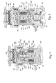
- Fig. 1 shown generally at 20a , is a first embodiment of the active fluid mounting.
- the active fluid mounting 20a is useful for controlling, and preferably minimizing, dynamic vibration (motion and force) transmitted between a vibrating member 21a , such as an aircraft or automotive engine or the like, and a structure 23a , such as an aircraft pylon, automotive frame, or the like.
- the active fluid mounting 20a comprises a passive mounting 27a having an active fluid element 28a which includes a defined acting axis and is preferably received in a hollow pocket 67a preferably formed through the inner member 22a , outer member 24a , and first flexible element in the passive mounting 27a .
- a first flexible element preferably including compressive elastomer elements 26a, 26a' which are preferably substantially aligned with a radial direction, flexibly interconnects the inner and outer members 22a, 24a.
- flexible elements 26a, 26a' are manufactured from laminated elastomer layers bonded to metal shims.
- Preferable elastomer materials for all elastomer sections described herein include natural rubber, synthetic rubber, blends of natural and synthetic rubber, silicone, and the like.
- passive mounting 27a acts as the primary isolator between structure 23a and vibrating member 21a and cartridge-like active fluid element 28a acts as a secondary isolator.
- the active fluid element 28a is arranged in parallel relationship with the passive mount 27a forming, in combination, what is referred to in this first embodiment as the active fluid mounting 20a .
- the active fluid mounting 20a preferably includes within the hollow portion 67a preferably formed through the outer member 24a , inner member 22a , and flexible elements 26a, 26a', an active fluid element 28a which is unitary, cartridge-like, self-contained, and easily and readily detachable. It should be understood that this cartridge-like active fluid element 28a allows for fast change-out during refurbishment, and/or tuning, etc. Further, in a distinguishing feature, the active fluid element 28a does not derive any of its volume stiffness Kv (to be described later), from the first flexible elements 26a, 26a' and interconnects (preferably by fastening means, such as bolts and/or retainers) between inner and outer members 22a, 24a. As such, the active fluid element 28a can be tuned "separately" from the passive mounting 27a , thereby allowing the same active fluid element 28a to be used with different passive mountings, for example, in multiple platforms (applications).
- a first cylindrically-shaped housing member 30a of the active fluid element 28a preferably attaches to the inner member 22a preferably by way of a third flexible member 50a, plate 52a (Fig. 2), rigid bracket 29a, and fasteners 25a, 25a', 25a", 25a"'.
- the second housing member 32a of active fluid element 28a is secured to outer member 24a via insertion in a pocket formed in an end of threaded insert 37a.
- the second housing member 32a is preferably secured and attached in place by split retainer ring 39a which is threadedly received within end of insert 37a. Retainer 39a may not be required if adequate precompression of the active element 28a is achievable. Precompression ensures that second housing member 32a is in contact with outer member 24a throughout the ordinary load range.
- Insert 37a is preferably threadedly received in an end of pilot 35a which is formed on the outer member 24a of passive mounting 27a. Pilot 35a is preferably received in an engine recess 73a.
- the outer member 24a is preferably manufactured from steel or aluminum and includes first and second halves 31a, 33a which are precompressed together and attached to vibrating member 21a , preferably by four engine bolts 45a, 45a' (the other two bolts are not shown).
- Inner member 22a is also preferably manufactured from steel and is bar-shaped, preferably attaches and interconnects to structure 23a by way of clevis 48a .
- clevis bolts 43a, 43a', and spacers 75a, 75a' attach clevis 48a to inner member 22a .
- Structure bolts 41a, 41a' preferably attach clevis 48a to structure 23a .
- the radial dynamic stiffness (compression stiffness) of passive mounting 27a shown would be about 70,000 lbf/in (12,258,876 N/m) at 250 Hz (250 1/s) at +/- 0.0005 in (+/- 0.0127 mm) input in compression (Radial Direction).
- Dynamic stiffness in the lateral direction is a factor of six or more less than radial, as the first elastomer members 26a, 26a' are loaded in pure shear in the lateral direction.
- the active fluid element 28a further comprises first housing member 30a , second housing member 32a , and a second flexible element 34a , such as the elastomeric tube form shown, for flexibly connecting first housing member 30a to second housing member 32a .
- the second flexible element 34a accommodates motion predominantly in the axial direction, yet substantially restrains radial motion.
- second flexible element 34a will accommodate limited angular and radial misalignment.
- the second flexible element 34a is preferably an annular shaped tube-form elastomer section and exhibits a dynamic axial stiffness of about 10,500 lbf/in (1,838,831 N/m) at 250 Hz (250 1/s) and +/- 0.0005 in (+/-0.0127 mm).
- the active fluid element 28a preferably includes at least one, and preferably two, first and second fluid chambers 36a, 38a within said active fluid element 28a each having a defined volume stiffness Kv associated therewith.
- volume stiffness Kv
- chambers that have a flexible compliance associated therewith, such as an elastomer element, will exhibit a volume stiffness Kv .
- the first fluid chamber 36a would exhibit a volume stiffness Kv of about 172,000 psi/in 3 (74,114 pascals/mm 3 ) and second fluid chamber 38a would exhibit a volume stiffness of about 500 psi/in 3 (215 pascals/mm 3 ) or less.
- the volume stiffness Kv of the second fluid chamber 38a would be "substantially", a factor of a hundred or more, less than the volume stiffness Kv of the first fluid chamber 36a and, therefore, can be neglected in all calculations.
- a substantially preferably electrically nonconductive and preferably incompressible fluid 40a such as a perfluorinated polyether, silicone fluid, hydraulic oil, or the like, is contained within, and substantially fills, the first and second fluid chambers 36a, 38a .
- substantially incompressible it is meant that the fluid 40a exhibits a bulk modulus (stiffness) of about 350,000 psi/in 3 (150,815 pascal/mm 3 ).
- a piston 42a which in this embodiment is preferably a hollow-cylindrical sleeve, i.e., ring-like, is contained within the active fluid element 28a and dynamically interacts with the fluid 40a in the first and said second fluid chambers 36a, 38a to cause dynamic pressure variations therein. This produces active dynamic forces which act between the inner member 22a and outer member 24a to control vibration therebetween.
- the piston 42a is inductively-driven and is preferably manufactured from a high density nonmagnetic material with high electrical conductivity, such as copper or brass.
- the area of action of the piston 42a is preferably substantially smaller than the area of the fluid pumping chambers 36a, 38a, therefore, the forces generated by driving the piston 42a can be significantly amplified, i.e., fluidically leveraged.
- MA should preferably be about 15 or more. In this fashion, the force created by the motor unit 46a is amplified or leveraged by about 20 times or more.
- the active fluid element 28a further includes means for driving said piston 42a housed internally within it.
- the means for driving the piston 42a preferably includes a coil 70a and magnet-and-pole assembly 44a which is further comprised of at least one permanent magnet, and preferably two permanent magnets 68a, 68a' and pole pieces 66a, 66a', 66a".
- Wound coil 70a is preferably manufactured from wound copper magnet wire of the appropriate size and number of winds to produce a dynamic magnetic field of an acceptable flux strength.
- Permanent magnets 68a, 68a' preferably have north N and south S poles oriented as shown in Fig. 2 and are preferably ring-type Neodymium-type, iron-boron, or other high strength magnets.
- the magnets 68a, 68a' cause a static magnetic field to be generated in the gap between inner pole 66a and outer pole 66a" (which is filled by the piston 42a and coil 70a ) which have lines of flux that act across the gap.
- Energizing coil 70a with an alternating electrical current causes (induces) current to flow in the hoop direction (circumferentially) about the nonmagnetic and conductive ring-like piston 42a because of the close proximity of piston 42a to coil 70a .
- the oscillating induced current flowing in the piston 42a creates a dynamically oscillating magnetic field which interacts with the static magnet field created by magnets 68a, 68a' and the dynamic magnetic field created by alternately energizing coil 70a .
- the piston 42a is preferably centered relative to poles 66a, 66a" by precompressed centering springs 65a, 65a', which are preferably helical steel coil springs, or the like.
- the piston 42a is included in an intermediate fluid chamber 84a which is fluidically interactive with the first and second fluid chambers 36a, 38a through ports 49a, 49a'.
- the magnets and pole pieces are slotted radially to minimize eddy currents from flowing tangentially.
- the weight of piston 42a in this embodiment is about 0.0224 lbf (0.0996 N) and the combined static stiffness of centering springs 65a, 65a' are preferably less than about 5.0 lbf/in (875 N/m). It should be understood that the mass of piston 42a , inertia of the fluid If, volume stiffness Kv of first fluid chamber, and axial stiffness of springs 65a, 65a', piston area Ap and ring area Ar , amongst other factors, may be appropriately chosen, such that the piston 42a will resonate at a particular design frequency fnat (to be fully described later herein).
- the masses, stiffnesses, and areas would be chosen such that the resonance of piston 42a occurs at a frequency preferably about 1.5 to 3 times higher than the highest frequency of vibration which is to be controlled.
- the resonant frequency fnat of the active fluid mounting 20a is preferably predominantly governed only by the volume stiffness Kv of the first flexible member 34a and mass of piston 42a and the Ap/Ar ratio. This is because the inertia of the fluid If in ports 49a, 49a' (preferably six per end) is preferably made negligible.
- the stiffnesses of centering springs 65a, 65a' are preferably made negligible, and the volume stiffness Kv2 of second fluid chamber 38a is substantially less than the volume stiffness Kv1 of the first fluid chamber 36a . Therefore, the volume stiffness Kv2 of the second fluid chamber 38a , spring stiffnesses Ks of centering springs 65a, 65a' and fluid inertia If may be ignored in calculations.
- this actively driven element 28a will produce about +/- 35 lbf (155 N) at about 250 Hz (250 1/s) and 0.0005 in (0.0127 mm) axial displacement when installed in passive mounting 27a but may produce forces as high as 92 lbf. (409 N).
- the performance is dictated by the current Ir that is induced into the inductively driven piston 42a .
- the following equations and examples are indicative of the process used to size, for example, active fluid element 28a including an inductively-driven piston 42a . It should be understood that the values listed are exemplary only, and not to be considered limiting.
- the maximum force Fa that can be achieved for continuous operation will generally be dictated by temperature considerations.
- the current Ic to the coil 70a must be limited.
- the maximum temperature stable force output Fa is approximately 120 lbf (533 N).
- the actual actuator force can be significantly amplified by the resonant effects and tuning the resonance to amplify forces at the desired operating frequency. Further, higher output forces are available for reacting to larger transient vibrations.
- the fluid inertia If in the flow ports 49a, 49a' located between the piston 42a and the first and second fluid chambers 36a, 38a adds to the effective mass of the piston 42a and must be considered in all dynamic calculations (although it may be made negligible via appropriate design).
- the resonant frequency fnat of inductively driven piston 42a must be placed well above the operating frequency f o of the active fluid mounting 20a, which, for this example, is approximately 255 Hz (255 1/s).
- the following approximate represents the undamped natural frequency fnat of the piston 42a assuming that Kv'2 is negligible.
- the best performance for this type of active fluid element 28a is obtained when operating at or near the "notch" of the complex stiffness curve, K * .
- the "notch frequency" f notch is preferably placed near the operating frequency, in this example, approx. 255 Hz (255 1/s), to achieve the best performance there, while still being able to achieve good, but less efficient, performance at lower operating frequencies.
- the piston 42a interacts with first and second fluid chambers 36a, 38a via fluid ports 49a, 49a' .
- fluid inertia in ports will be minimized as compared to the mass of piston 42a .
- the coil 70a and magnet-and-pole assembly 44a is included entirely within a drop-in motor unit 46a .
- the motor unit 46a is an integral unit which can be easily and quickly changed out. This is desirable, as it allows ease of refurbishment as well as the ability to test multiple motor concepts and allows ease of tuning.
- the motor unit 46a is preferably comprised of two permanent magnets 68a, 68a', a slender nonmagnetic alignment rod 51a for axial alignment, an inductively-driven conductive and nonmagnetic piston 42a , low-stiffness coil centering springs 65a , 65a' , a wound copper wire coil 70a , high magnetic permeability pole pieces 66a , 66a', 66a ", and locating pin 55a for maintaining rotational alignment.
- the magnetic circuit which carries magnetic flux, is defined by pole pieces 66a, 66a', 66a", which are manufactured from high magnetic permeability material, such as steel, but which is preferably a highly electrically resistive material also, and high strength permanent magnets 68a, 68a' .
- the magnetic circuit is preferably substantially entirely contained within the motor unit 46a . Notably, there may be some stray magnetic flux outside of the confines of the magnetic circuit.
- the magnetic fields Ha are approximated by the dotted flux lines shown. Electrical leads 60a, 60a' provide alternating electrical current to the wound wire coil 70a to dynamically energize same.
- Lead 60a is sealed via lead seal 62a , which is formed of a potting material, a sealed electrical connector, a bonded seal, or the like, and prevents the fluid 40a from leaking out.
- Removable and sealed fill plug 74a is used for filling the active fluid element 28a with fluid 40a and for access when bonding second flexible element 34a .
- the active fluid element 28a also, preferably, includes a volume compensator 57a which includes a flexible partition 58a , an air chamber 59a , and a fill valve 56a .
- the flexible partition 58a is preferably an elastomer diaphragm which includes a flexible periphery seal 64a formed thereon which is compressed upon assembly of threaded cap 54a into body 61a to seal same. Cap 54a and body 61a , together, make up the first housing member 30a .
- the air chamber 59a is preferably filled with a compressible gas, such as air or nitrogen, to a sufficient predetermined positive prepressure.
- volume compensator 57a also allows expansion of the fluid 40a due to changes in temperature, thereby minimizing pressure buildups within the active fluid element 28a which may change the properties of the active fluid element 28a or even cause rupture of the second flexible element 34a .
- a volume compensator is described in commonly assigned US Pat. No. 4,811,919 to Jones.
- third flexible element 50a is included which functions to decouple lateral loads from the active fluid element 28a .
- the third flexible member 50a is preferably manufactured from laminated elastomer layer and metal shims, and is preferably bonded directly to both cap 54a and plate 52a .
- Plate 52a is preferably attached to bracket 29a by fasteners, 25a and 25a' .
- the third flexible member 50a is very stiff in the direction of the acting axis and substantially less stiff along the lateral axis. This allows the active fluid element 28a to effectively transmit dynamic loads along the radial (acting) axis, yet be able to accommodate lateral displacements applied to the passive mounting 27a thereby reducing lateral loading.
- second elastomer section 34a allows axial displacement because of compressive loads applied to first elastomer sections 26a, 26a' .
- the third flexible member 50a would preferably have a stiffness in the direction of the acting axis of about 450,000 lbf/in (78.8 MN/m) and a lateral stiffness of about a factor of a hundred less (approx. 4,500 lbf/in or less) (788.1 KN/m) and is manufactured from natural rubber, synthetic elastomer, blends of natural and synthetic, and silicone elastomer, or the like.
- the novel inductively driven piston arrangement described herein can be incorporated in any active fluid mounting.
- the motor unit 46a may be interchanged with the motor unit 46f of Fig. 9a .
- Fig. 3 another embodiment of active fluid element 28b is illustrated which includes a first housing member 30b , second housing member 32b , second flexible element 34b and is attached between bracket 29b and insert 37b .
- the piston 42b includes a rod-like protrusion which is slidably received in a bore 47b .
- the piston 42b is loosely fit in the bore 47b and the dimensions are such that only a small amount of fluid 40b can flow through the gap therebetween.
- the piston 42b is preferably integral with, and directly attached to, bobbin 72b which has a wound coil 70b of magnet wire thereon.
- the piston 42b and bobbin 72b comprise an assembly, preferably made of one-piece construction, and manufactured from a nonmagnetic material, such as aluminum or plastic.
- Magnet-and-pole assembly 44b includes a disc-shaped permanent magnet 68b and poles 66b, 66b' .
- Pole 66b' has a recess 53b formed therein for receiving at least a portion of annular-shaped coil 70b and bobbin 72b .
- Magnet-and-pole assembly 44b is preferably received and retained in a recessed pocket formed on the end of insert 37b .
- a retaining ring may not be required if there is sufficient axial precompression of the active fluid element 28b along its acting axis. Together, magnet-and-pole assembly 44b and coil 70b make up the coil and magnet assembly 44b .
- First housing member 30b is comprised of magnet-and-pole assembly 44b and body 61b .
- magnet-and-pole assembly 44b is threaded onto cylindrical body 61b , which is preferably manufactured from nonmagnetic material.
- Puck-shaped pole piece 66b, cup-shaped pole piece 66b' are manufactured from a high magnetic permeability material.
- pole pieces 66b, 66b', magnet 68b , and coil 70b comprise the magnetic circuit.
- a portion of the magnetic field Hb is approximately illustrated by the dotted magnetic flux lines shown.
- Three centering springs 65b, 65b', 65b” preferably center and flexibly suspend the piston 42b and its integral wound coil 70b.
- the driving electrical current is received through leads 60b, 60b' and channeled into wound coil 70b through incoming path, comprising spring 65b" and incoming lead 60b" and out through outgoing path, comprising outgoing lead 60b"' and spring 65b.
- the terms "incoming” and “outgoing” are merely illustrative, as it should be understood that current through lead 60b, 60b' is preferably Alternating Current (AC).
- Channeling electrical current through springs 65b, 65b” is preferable to minimize dynamic fatigue of leads connecting to moving coil 70b .
- Commonly assigned US Pat. No. 5,323,133 to Heath et al. describes a "Method And Apparatus For Making Electrical Connection With A Moveable Member.”
- a strain relief loop 69b may be used to prevent of fatigue of leads 60b, 60b' .
- Second and third flexible elements 34b, 50b serve the same purposes as described with reference to the afore-mentioned Fig. 2 embodiment.
- Tunable volume stiffness Kv2 of second fluid chamber 38b is provided by flexible partition 58b , such as flexible steel bellows shown.
- the volume compensator 57b comprises air chamber 59b and flexible partition 58b .
- the volume stiffness Kv2 provided by the flexible partition 58b is substantially less than the volume stiffness Kv1 of the first flexible member 34b .
- the mass of piston 42a , coil 70b and bobbin 72b assembly, and stiffness of centering springs 65b, 65b' , 65b" , and volume stiffness Kv1 of the first flexible member 34b are preferably tuned to provide the appropriate position of the notch f notch .
- Fig. 4 illustrates another embodiment of active fluid element 28c which comprises first and second housing members 30c, 32c flexibly interconnected by second flexible element 34c , first and second fluid chambers 36c, 38c, an annular-shaped piston 42c interacting with fluid 40c contained within first and second fluid chambers 36c, 38c, preferably through ports 49c, 49c' and including means for driving the piston 42c .
- the piston 42c is comprised of bobbin 72c , which is preferably nonmagnetic and manufactured from aluminum or plastic, and a number of hoop winds of copper wire comprising a wound coil 70c .
- Piston 42c is preferably centered and supported relative to pole pieces 66c , 66c' by coil centering springs 65c, 65c' which are preferably axially-precompressed.
- Magnet-and-pole assembly 44c is comprised of pole pieces 66c, 66c', 66c" and a plurality of opposed permanent magnets 68c, 68c' .
- Second housing member 32c is comprised of body 61c and threaded cap 54c .
- Body 61c is further comprised of pole pieces 66c, 66c' and 66c" and magnets 68c, 68c', which comprise the complete magnetic circuit.
- Cap 54c is preferably manufactured from a nonmagnetic material, such as brass or aluminum and is received in recessed pocket in insert 37c which is inserted in passive mounting 27a as shown in Fig. 1 .
- Cap 54c threads onto body 61c and secures pole piece 66c" in place, seals the interface, and precompresses centering springs 65c, 65c' which properly centers the piston 42c .
- Volume compensator 57c provides the second volume stiffness Kv2 to second fluid chamber 38c and allows for fluid expansion and pressurization.
- threaded ring retainer 76c secures flexible partition 58c (preferably a flexible steel bellows) in place.
- Decoupler 50c provides lateral decoupling of loads applied by inner member 22a of passive mounting 27a (Fig. 1) to bracket 29c.
- the active fluid element 28c is tuned by adjusting the mass of the coil 70c and bobbin 72c, inertia of the fluid 40c contained in ports 49c, 49c', stiffness of centering springs 65c, 65c', and volume stiffness Kv1 of the first flexible member 34c.
- the volume stiffness Kv2 of second fluid chamber 38c is assumed to be negligible in this embodiment.
- Energizing leads 60c, 60c' with electrical current and, thereby, supplying electrical current to wound coil 70c causes piston 42c to dynamically oscillate, as commanded, along an acting axis within intermediate chamber 84c and pump fluid 40c into and out of ports 49c, 49c' and into and out of first and second fluid chambers 36c, 38c .
- This causes fluid pressures to act inside the active fluid element 28c and produce axially-acting active oscillatory forces between bracket 29c and insert 37c .
- Fig. 5 illustrates a representative performance curve of the active fluid mounting 20a of the embodiment shown in Fig. 1 including therein the active fluid element 28a described with reference in Fig. 2 .
- the graphical plot illustrates dynamic free displacement (when installed between the inner member and outer member of the active fluid mounting in the radial direction) in in/Amp (m/Amp) versus frequency in Hz (1/s).
- a family of normalized curves is shown for various amperage inputs to the coil.
- the active fluid element 28c is very efficient to operate at its tuned frequency f notch (approx. 245-255 Hz) (245-255 1/s) depending upon input condition. This is attributable to the tuned resonance of the fluid 40a and piston 42a within the active fluid element 28a which amplify forces obtainable at the notch frequency f notch .
- Fig. 6 illustrates a representative power curve of the active fluid mounting 20a and graphically illustrates that the active fluid element 28a only requires a small power input (approx. 0.00537 hp) (4 Watts) ( to operate at, or near, the tuned frequency (approx. 255 Hz) (255 1/s) at +/- 0.0005 in (+/- 0.0127 mm) free displacement. This results in a dynamic force output of about +/- 35 lbf (155.7 N) at the notch frequency f notch at that particular amplitude.
- the active fluid element 28a is still relatively efficient, as the notch frequency f notch of the active fluid element 28a improves performance even at other frequencies. It should also be understood that the active fluid element 28a may be driven at multiple frequencies at once.
- the notch frequency f notch can be tuned at an N2 frequency of an aircraft engine, such that the active fluid mounting 20a is most efficient there, and the active fluid mounting 20a would still be relatively efficient at N1 (approx. 120 Hz).
- the active fluid element can produce approx. 90 lbf (400.3 N) at 250 Hz (250 1/s) on a semi-sustained basis, if needed to counter transient vibrations, etc.
- Fig. 7 illustrates another embodiment of active fluid element 28d which comprises first and second housing members 30d, 32d, second flexible element 34d , a single fluid chamber 36d , a piston 42d interacting with fluid 40d contained therein, and including electromagnetic means for driving the piston 42d .
- the piston 42d is part of an assembly which is comprised of a bobbin 72d , which is preferably nonmagnetic and manufactured from aluminum, plastic, or the like, and a number of hoop winds of copper wire comprising a wound coil 70d .
- the piston 42d is preferably centered and supported by centering springs 65d, 65d' .
- spring 65d is an annular-shaped tube-form elastomer section and provides part of the volume stiffness Kv1 of first fluid chamber 36d .
- Magnet-and-pole assembly 44d is comprised of at least one permanent magnet 68d and pole pieces 66d, 66d' .
- Second housing member 32d is preferably comprised of body 61d and threaded cap 54d .
- Body 61d is further comprised of pole pieces 66d and 66d' , and magnet 68d which comprise the magnetic circuit.
- Cap 54d is preferably manufactured from a nonmetallic material, such as aluminum. Cap 54d threads onto body 61d which precompresses centering spring 65d' , which properly centers and positions piston 42d relative to pole pieces 66d, 66d' .
- the active fluid element 28d is preferably tuned by adjusting the masses of the piston 42d , coil 70d and bobbin 72d , dynamic axial stiffness of centering springs 65d, 65d' , dynamic volume stiffness Kv1 of the first flexible member 34d .
- Energizing leads 60d, 60d' with electrical current and, thereby, supplying electrical current (AC) to the wound coil 70d causes the piston 42d to dynamically oscillate (because of interaction of static field produced by disc-shaped permanent magnet 66d and dynamic field produced by coil 70d ), as commanded, and compress the fluid 40d in first fluid chamber 36d .
- This causes fluid pressure variations to act inside the active fluid element 28d and produce active dynamic forces between bracket 29d and insert 37d .
- third flexible element 50d provides lateral decoupling as before-mentioned.
- Fig. 8 illustrates another active fluid element 28e which comprises first and second housing members 30e, 32e, second flexible element 34e , a "single" fluid chamber, 36e and a piston 42e interacting with fluid 40e contained therein, and including electromagnet means for driving the piston 42e .
- the piston 42e is comprised of a portion of magnet-and-pole assembly 44e which comprises pole pieces 66e, 66e', 66e" and disc-shaped permanent magnet 68e .
- the magnet 68e and poles 66e, 66e' secured on opposite sides thereof comprise the piston 42e .
- the piston 42e is driven by a dynamic magnetic field produced by a plurality of wound coils 70e, 70e' surrounding the poles 66e, 66e' and magnet 68e .
- Wound coils 70e, 70e' are wound in electrical series and in opposite directions (CW and CCW, respectively) such that alternating current applied to leads 60e, 60e' produces dynamic magnetic fields about coils 70e, 70e' which are preferably in opposition to one another.
- Piston 42e is preferably centered and supported by centering springs 65e, 65e' .
- spring 65e is a welded steel bellows spring which exhibits very high volume stiffness Kv , yet a low stiffness along its acting axis.
- the spring 65e does not contribute to the volume stiffness Kv1 appreciably, as the volume stiffness of flexible element 34e is much softer.
- centering spring 65e would preferably be nonmagnetic and glued to pole piece 66e or precompressed thereagainst.
- Second housing member 32e is preferably comprised of soft-magnetic body 61e and nonmagnetic threaded caps 54e, 54e' .
- Body 61e comprises pole piece 66e" .
- Caps 54e, 54e' thread onto body 61e and precompress centering springs 65e, 65e' which properly centers and positions piston 42e relative to coils 70e, 70e' .
- the active fluid element 28e is tuned by adjusting the mass of the piston 42e , stiffness of centering springs 65e, 65e' , and volume stiffness Kv1 of the first flexible member 34e .
- Energizing leads 60e, 60e' with electrical current supplies electrical current to wound coils 70e, 70e' and causes piston 42e to dynamically oscillate, as commanded, and compress fluid 40e in fluid chamber 36e .
- This causes fluid pressures to act inside the active fluid element 28e and produce active forces between bracket 29e and insert 37e along the acting axis.
- Third flexible element 50e provides lateral decoupling.
- Fig. 9a illustrates another embodiment of active fluid mounting, and in particular, an active pylon isolator 20f , several of which interconnect in parallel relationship in a linkage-like fashion between a vibrating helicopter transmission 21f and a helicopter fuselage, or other helicopter structure 23f .
- the active pylon isolator 20f produces active (positive and/or dissipative) forces to isolate vibrations between the transmission 21f and structure 23f .
- this isolator 20f has potentially broad applicability, and may be interconnected, and isolate vibrations, between any two relatively vibrating members.
- This active pylon isolator 20f functions as a linkage-like member, in that the device preferably attaches to the various structures/vibrating members at its ends by pin connections 78f, 78f' .
- the pin connections 78f, 78f' each preferably comprise a bolt 97f, 97f', or the like, having a pilot portion 83f, 83f' which is rotatable within a bushing 91f, 91f' pressed into bracket 93f, 93f' .
- Bracket 93f, 93f' attaches to structure 23f and vibrating member 21f by bolts (not shown), or the like.
- the fluid 40f which is preferably silicone, is pumped by a cartridge-like motor unit 46f received inside a pocket 81f formed in the high strength, preferably nonmagnetic (ex. aluminum or 300 series stainless steel) inner member 22f .
- the motor unit 46f is preferably comprised of a magnet-and-pole assembly 44f, an annular-shaped preferably nonmagnetic piston 42f, and centering springs 65f, 65f'.
- the motor unit 46f functions to actively pump the fluid 40f .
- the motor unit 46f is self-contained and, thus, easily changed out.
- the magnet-and-pole assembly 44f comprises pole pieces, 66f, 66f', 66f", 66f"' permanent magnets 68f, 68f', springs 65f, 65f', and piston 42f .
- the pilots 88f, 88f' formed on rod-like center pole piece 66f"' are preferably press fit over slightly smaller receiving bores formed in end cap pole pieces 66f, 66f" . Assembly appropriately precompresses coil springs 65f, 65f' . Magnet-and-pole assembly 44f carries the static magnetic field produced by the generally opposed permanent magnets 68f, 68f' . Estimates of the lines of flux are indicated as dotted lines.
- the moveable piston 42f as shown in Fig. 9b includes a coil 70f comprising a plurality of circumferentially wound coated copper magnet wires wound about a nonmagnetic, yet electrically conductive bobbin 72f , and may include additional nonmagnetic yet dense (ex. tungsten) annular tuning mass 80f attached thereto.
- the additional nonmagnetic mass 80f may be used for tuning the dynamic properties of the mounting 20f .
- the piston 42f is preferably annular-shaped and encircles inner pole piece 66f"' .
- piston 42f is surrounded by intermediate pole piece 66f' and is flexibly suspended by at least one, and preferably two, nonmagnetic yet conductive (ex.
- centering springs 65f, 65f' which act to center the piston 42f relative to the afore-mentioned pole pieces 66f', 66f"' , as well as provide appropriate spring rate for dynamics.
- the pumping area Ar of piston 42f is a factor of magnitude or more smaller than the pumping area Ap of the fluid chambers 36f, 38f, thereby providing a hydraulic lever.
- the oscillating electrical current to the coil 70f is provided through the springs 65f, 65f' via leads 60f, 60f' .
- a first end 79f of coated coil 70f is attached to lower spring 65f' by soldering, or the like.
- a second end 79f' of coil 70f is secured to conducting, yet nonmagnetic (preferably tungsten or copper), tuning mass 80f by soldering, or the like.
- bobbin 72f and tuning mass 80f are shown as two pieces, preferably, they would be manufactured from one piece construction.
- the electrical current from lead 60f flows into, and out of, turned out portions 89f of springs 65f .
- the electrical connection is made by soldering, or the like.
- Shrink wrap 90f or the like (shown as sectioned for clarity), will then be heated to shrink over the lead 60f and turn out 89f to further strengthen the electrical connection.
- the connection between lead 60f' and spring 65f' is substantially similar.
- the shrink wrap 90f may extend further onto the active portions of the coils as illustrated by dotted lines 90f' . Therefore, the complete electrical circuit connecting leads 60f, 60f' is comprised of springs 65f, 65f' , coil 70f , and additional mass 80f .
- the leads 60f , 60f ' rest in localized slots 77f formed in pole pieces 66f, 66f', 66f" and magnets 68f, 68f' ( Fig. 9d ) and exit the pocket 81f formed in inner member 22f through the lead seal 62f which prevents fluid leakage
- the coil 70f upon being electrically energized with an oscillating electrical current produces a dynamic magnetic field which interacts with the static field produced by permanent magnets 68f, 68f' thereby causing the piston 42f to oscillate axially.
- the piston 42f is preferably contained within a third fluid chamber 84f formed within the motor unit 46f .
- This third fluid chamber 84f is preferably fluidically interconnected to the first and second fluid chambers 36f, 38f by way of preferably circular ports 49f, 49f' (preferably six per end).
- the ports 49f, 49f' may be slot segments and may include fluid inertia If .
- the motor unit 46f is secured in place within inner member 22f by inserting the components into first inner member half 86f and then threading second inner member half 86f' thereon. Seals 87f, 87f' prevent fluid escape.
- the motor unit 46f is preferably tuned by adjusting the mass of the piston 42f via adjusting the mass of additional tuning mass 80f , the axial stiffnesses of centering springs 65f, 65f' and the dynamic volume stiffnesses Kv'1 Kv'2 of the first flexible member 26f (via bonding in a different stiffness elastomer or changing the thickness or length of the annular elastomer section).
- the volume stiffness of the mounting 20f is derived from the first elastomer section 26f .
- the piston 42f When the piston 42f dynamically oscillates, as electrically commanded, it alternately compresses fluid 40f in first and second fluid chambers 36f, 38f . This causes dynamic fluid pressure to act inside the first fluid chamber 36f between the inner member 22f and the outer member 24f and in the second fluid chamber 38f between inner member 22f and an inner portion of outer member linkage 82f' (which is interconnected to outer member 24f ), thereby producing active dynamic forces between inner member linkage 82f and outer member linkage 82f' along the acting axis (designated by arrow F ).
- the outer member 24f is preferably comprised of a cap 92f and a annular sleeve 94f . The cap 92f threads into outer member linkage 82f'.
- Fill plug 74f provides the means for filling the mounting 20f with fluid 40f .
- the inner member 22f preferably attaches to inner member linkage 82f via three equally-radially-spaced bolts 85f (only one is shown) which are inserted through bushings 71f .
- outer member 24f preferably attaches to outer member linkage 82f' by threading. Because linkages 82f, 82f' are preferably pin loaded, a third flexible element is not needed to provide lateral load decoupling.
- pin joints 78f, 78f' are shown as being aligned. Likewise, they may be rotated 90 degrees from each other providing pivoting in multiple directions.
- the compensator 57f is comprised of a divider 96f which divides the second fluid chamber 38f from the compensator chamber 98f , a flexible partition 58f (preferably a fabric-reinforced rolling diaphragm) which divides the air chamber 59f and the compensator chamber 98f , and a compensator coil spring 99f causing an axial deflection of support cup 95f .
- This spring-loaded cup 95f provides static pressurization to the fluid 40f in the mounting 20f .
- This pressure which is thought to prevent cavitation under certain conditions, may be augmented by pressurizing gas chamber 59f with a pressurizing valve 56f .
- the motor unit 46f may be easily removed/replaced during refurbishment or tuning. Further, it should be recognized that the other motor units (ex. 46a ) described herein could easily be incorporated into the fluid mounting 20f .
Landscapes
- Engineering & Computer Science (AREA)
- General Engineering & Computer Science (AREA)
- Mechanical Engineering (AREA)
- Combined Devices Of Dampers And Springs (AREA)
Claims (16)
- Aktives Fluidlager, gekennzeichnet durchdadurch gekennzeichnet,(a) ein inneres Element (22),(b) ein äußeres Element (24)(c) ein flexibles Element (26) zum flexiblen Halten des inneren Elementes relativ zum äußeren Element,(d) ein einstückiges, aktives Fluidelement (28), welches kartuschenartig und leicht lösbar ausgebildet ist,
daß das einstückige, aktive Fluidelement (28) wenigstens eine Fluidkammer (36) aufweist, welche eine Voluniensteifigkeit (Kv) aufweist, um aktive Kräfte zwischen dem inneren und äußeren Element zur Verfügung zu stellen. - Aktives Fluidlager nach Anspruch 1, dadurch gekennzeichnet, daß das kartuschenartige, aktive Fluidelement (28) ferner folgendes aufweist:(a) ein erstes Gehäuseelement (30) zum Verbinden mit dem inneren Element (22) oder dem äußeren Element (24),(b) ein zweites Gehäuseelement (32) zum Verbinden des inneren Elementes (22) mit dem äußeren Element (24),(c) ein zweites flexibles Element (34) zum flexiblen Halten des ersten Gehäuseelementes relativ zum zweiten Gehäuseelement und zur Aufnahme von Bewegungen zwischen diesen,(d) eine erste Fluidkammer (36) innerhalb des kartuschenartigen, aktiven Fluidelementes, dem eine Volumensteifigkeit zugeordnet ist, wobei die erste Fluidkammer keine Volumensteifigkeit von dem ersten flexiblen Element (26) ableitet,(e) ein Fluid (40), welches in der ersten Fluidkammer enthalten ist;(f) einen Kolben (42) innerhalb des aktiven Fluidelementes, welcher mit der ersten Fluidkammer zusammen wirkt, um dynamische Druckvariationen zu bewirken, die aktive dynamische Kräfte erzeugen, die zwischen dem inneren Element und dem äußeren Element wirken, und(g) Mittel (44) zum Antrieb des Kolbens.
- Aktives Fluidlager nach Anspruch 2, dadurch gekennzeichnet, daß die Mittel (44) zum Antrieb des Kolbens eine Spule-Magnet-Anordnung innerhalb des kartuschenartigen, aktiven Flüidelementes (28) sind und femer eine Wickelspule und einen Permanentmagneten aufweisen.
- Aktives Fluidlager nach Anspruch 3, dadurch gekennzeichnet, daß die Spule-Magnet-Anordnung (44), der Kolben (42) und Polstücke (66) in einer Motoreinheit (46) enthalten sind, die in dem kartuschenartigen, aktiven Fluidelement (28) aufgenommen ist.
- Aktives Fluidlager nach Anspruch 3, dadurch gekennzeichnet, daß eine Feder (65) den Kolben (42) flexibel hält.
- Aktives Fluidlager nach Anspruch 3, dadurch gekennzeichnet, daß der Kolben (42) gleitbar in einer Bohrung aufgenommen ist, welche mit der ersten Fluidkammer (36) verbunden ist, wobei der Kolben direkt mit der Wikkelspule verbunden ist und sich immer axial mit dieser bewegt.
- Aktives Fluidlager nach Anspruch 3, dadurch gekennzeichnet, daß die Wickelspule und der Permanentmagnet (44) relativ zueinander stationär sind und daß der Kolben (42) aufgrund induktiver Kopplung zwischen dem Kolben und der Spule-Magnet-Anordnung (44) induktiv angetrieben ist.
- Aktives Fluidlager nach Anspruch 2, dadurch gekennzeichnet, daß der Kolben (42) eine Anordnung aus einer nichtmagnetischen Haspel (72) mit einem Draht, der auf den Umfang der Haspel aufgewickelt ist und die Wikkelspule (70) ausbildet, umfaßt, wodurch ein Endabschnitt des Kolbens dynamisch mit dem Fluid (40) in der ersten Fluidkammer (36) bei Anregung der Wickelspule zusammenwirkt.
- Aktives Fluidlager nach Anspruch 2, dadurch gekennzeichnet, daß ein drittes flexibles Element (50) vorgesehen ist, welches seitliche Lasten, die auf das kartuschenartige, aktive Fluidelement (28) wirken, entkoppelt.
- Aktives Fluidlager nach Anspruch 2, dadurch gekennzeichnet, daß der Kolben (42) ebenfalls mit einer zweiten Fluidkammer (38) innerhalb des kartuschenartigen, aktiven Fluidelementes (28) dynamisch zusammenwirkt.
- Aktives Fluidlager nach Anspruch 2, dadurch gekennzeichnet, daß das kartuschenartige, aktive Fluidelement (28) in einem in dem inneren Element ausgebildeten Hohlraum aufgenommen ist und Abschnitte desselben starr am inneren Element (22) und dem äußeren Element (24) befestigt sind.
- Aktives Fluidlager nach Anspruch 2, dadurch gekennzeichnet, daß der kolben (42) in einer Zwischenfluidkammer (84) enthalten ist, die ebenfalls Fluid enthält, wobei die Zwischenfluidkammer mit der ersten (36) und zweiten (38) Fluidkammer über Öffnungen (49) zusammenwirkt.
- Aktives Fluidlager nach Anspruch 1, ferner gekennzeichnet durch:(a) eine erste Fluidkammer (36) mit einer ersten Volumensteifigkeit,(b) einer zweiten Fluidkammer (38) mit einer zweiten Volumensteifigkeit,(c) ein Fluid (40), welches in der ersten und zweiten Fluidkammer enthalten ist,(d) eine Zwischenfluidkammer (84), welche ebenfalls Fluid enthält und mit der ersten und zweiten Fluidkammer über Öffnungen (49) zusammenwirkt,(e) einen bewegbaren Kolben (42) innerhalb der Zwischenkammer,(f) eine Feder (65), welche den beweglichen Kolben flexibel hält,(g) einen Permanentmagnet (68), welcher ein statisches Magnetfeld erzeugt,(h) Polstückmittel (66), welche das statische Magnetfeld in Richtung des bewegbaren Kolbens führen, und(i) eine Spule (70), welche bei elektrischer Erregung mit elektrischem Wechselstrom ein dynamisch variierendes Magnetfeld erzeugt, welches mit dem statischen Magnetfeld zusammenwirkt, um den beweglichen Kolben oszillierend zu bewegen, was ein Pumpen des Fluids durch die Öffnungen und in bzw. aus der ersten und zweiten Fluidkammer hinein bzw. heraus bewirkt.
- Aktives Fluidlager nach Anspruch 1, ferner gekennzeichnet durch:(a) eine erste Fluidkammer(36) mit einer Volumensteifigkeit,(b) eine zweite Fluidkammer (38) mit einer Volumensteifigkeit,(c) ein Fluid (40), welches in der ersten und zweiten Fluidkammer enthalten ist,(d) eine Motoreinheit (46), welche in dem kartuschenartigen, aktiven Fluidelement (28) enthalten ist, wobei die Motoreinheit folgendes umfaßt:(i) einen bewegbaren Kolben (42), welcher zum Pumpen des Fluids zu und von der ersten und zweiten Fluidkammer ausgebildet ist,(ii) eine Feder (65), welche den bewegbaren Kolben flexibel hält,(iii) einen Permanentmagneten (68), welcher ein statisches Magnetfeld erzeugt(iv) Polstückmittel (66), welche das statische Magnetfeld in Richtung des bewegbaren Kolbens führen, und(v) eine Spule (70), welche bei elektrischer Erregung den beweglichen Kolben oszilliert.
- Aktives Fluidlager nach Anspruch 1, ferner gekennzeichnet durch:(a) eine erste Fluidkammer (36) mit einer ersten Volumensteifigkeit und einem ersten Pumpbereich,(b) eine zweite Fluidkammer (38) mit einer zweiten Volumensteifigkeit und einem zweiten Pumpbereich,(c) einen Fluidkanal, welcher die erste und zweite Kammer miteinander verbindet,(d) ein Fluid (40), welches in der ersten und zweiten Fluidkammer sowie dem Fluidkanal enthalten ist,(e) einen nichtmagnetischen, bewegbaren Kolben (42), welcher einen dritten, beweglich in dem Fluidkanal angeordneten Pumpbereich aufweist, um das Fluid zu pumpen, wobei der dritte Pumpbereich ein Zehntel der Größe des ersten Pumpbereiches und des zweiten Pumpbereiches oder weniger aufweist,(f) Federmittel (65), welche mit dem bewegbaren Kolben verbunden sind und diesen flexibel halten,(g) einen Permanentmagnet (68), der ein statisches Magnetfeld erzeugt,(h) Polstückmittel (66), welche das statische Magnetfeld in Richtung des bewegbaren Kolbens führen, und(i) eine Spule (70), welche bei elektrischer Erregung mit elektrischem Wechselstrom ein dynamisch variierendes Magnetfeld erzeugt, welches mit dem statischen Magnetfeld zusammenwirkt, um den beweglichen Kolben oszillierend zu bewegen, was ein Pumpen des Fluids durch die Öffnungen und in bzw. aus der ersten und zweiten Fluidkammer hinein bzw. heraus bewirkt.
- Aktives Fluidlager nach Anspruch 1, dadurch gekennzeichnet, daß das flexible Element das innere (22) und das äußere Element (24) verbindet, wobei das innere und das äußere Element jeweils ein Schwenklager an ihren jeweiligen Befestigungspunkten aufweisen.
Applications Claiming Priority (3)
| Application Number | Priority Date | Filing Date | Title |
|---|---|---|---|
| US835433 | 1997-04-08 | ||
| US08/835,433 US5957440A (en) | 1997-04-08 | 1997-04-08 | Active fluid mounting |
| PCT/US1998/006804 WO1998045615A1 (en) | 1997-04-08 | 1998-04-07 | Active fluid mounting |
Publications (2)
| Publication Number | Publication Date |
|---|---|
| EP0974015A1 EP0974015A1 (de) | 2000-01-26 |
| EP0974015B1 true EP0974015B1 (de) | 2003-09-24 |
Family
ID=25269495
Family Applications (1)
| Application Number | Title | Priority Date | Filing Date |
|---|---|---|---|
| EP98915315A Expired - Lifetime EP0974015B1 (de) | 1997-04-08 | 1998-04-07 | Aktives flüssigkeitslager |
Country Status (5)
| Country | Link |
|---|---|
| US (1) | US5957440A (de) |
| EP (1) | EP0974015B1 (de) |
| CA (1) | CA2285931A1 (de) |
| DE (1) | DE69818443T2 (de) |
| WO (1) | WO1998045615A1 (de) |
Families Citing this family (32)
| Publication number | Priority date | Publication date | Assignee | Title |
|---|---|---|---|---|
| US6082719A (en) * | 1998-05-12 | 2000-07-04 | Trw Inc. | Spacecraft antenna vibration control damper |
| US6394432B1 (en) * | 1998-06-10 | 2002-05-28 | Lord Corporation | Vibration and/or shock absorbing devices and compensator elements utilized therein |
| US6695106B2 (en) | 2000-09-26 | 2004-02-24 | Bell Helicopter Textron, Inc. | Method and apparatus for improved vibration isolation |
| US6378851B1 (en) | 2000-10-25 | 2002-04-30 | Lord Corporation | Fluid and elastomer apparatus with discrete volume compensator and secondary compliance |
| US7182324B2 (en) * | 2002-04-19 | 2007-02-27 | Polycom, Inc. | Microphone isolation system |
| US7178794B2 (en) * | 2002-09-10 | 2007-02-20 | Seagate Technology Llc | Fluid isolator assembly and floating elastomeric damping element |
| EP2182240B1 (de) * | 2002-09-24 | 2014-08-06 | Bell Helicopter Textron Inc. | Ein Verfahren zur Regelung der akustischen Strahlung eines Schiffs |
| US6758466B2 (en) * | 2002-11-06 | 2004-07-06 | Lord Corporation | Fluid-elastomeric damper assembly including internal pumping mechanism |
| US7270321B2 (en) * | 2002-11-06 | 2007-09-18 | Lord Corporation | Fluid-elastomeric damper assembly including internal pumping mechanism |
| US6896109B2 (en) * | 2003-04-07 | 2005-05-24 | Csa Engineering, Inc. | Magnetorheological fluid vibration isolator |
| FR2928344B1 (fr) * | 2008-03-06 | 2011-01-21 | Hutchinson | Dispositif d'amortissement et systeme de rotor d'aerodyne l'incorporant |
| FR2939103B1 (fr) * | 2008-12-01 | 2011-01-21 | Airbus France | Systeme hydraulique de transmission d'efforts entre un turbopropulseur d'aeronef et un dispositif d'accrochage |
| EP2368066B1 (de) | 2008-12-18 | 2014-08-20 | Bell Helicopter Textron Inc. | Vorrichtung für verbesserte schwingungsdämpfung |
| US8272786B2 (en) * | 2009-02-18 | 2012-09-25 | Honeywell International Inc. | Vibration isolation mounting assembly |
| US8256750B2 (en) * | 2009-02-18 | 2012-09-04 | Honeywell International Inc. | Vibration isolation mounting assembly |
| CN102405359B (zh) | 2009-03-12 | 2015-02-11 | 贝尔直升机泰克斯特龙公司 | 用于改进振动隔离的方法及设备 |
| EP2507531B1 (de) * | 2009-12-01 | 2014-04-16 | Bell Helicopter Textron Inc. | Vorrichtung für verbesserte schwingungsisolation |
| US8702377B2 (en) | 2010-06-23 | 2014-04-22 | Honeywell International Inc. | Gas turbine engine rotor tip clearance and shaft dynamics system and method |
| CN103782057B (zh) * | 2011-07-12 | 2016-04-13 | 北京京西重工有限公司 | 双泵式磁流变液压拉杆组装件 |
| US8882091B2 (en) | 2011-11-11 | 2014-11-11 | Textron Innovations Inc. | Vibration isolation system |
| CN102734379B (zh) * | 2012-06-09 | 2013-12-11 | 哈尔滨工业大学 | 基于电磁与静压气浮复合支撑的主动隔振装置 |
| US9353820B2 (en) * | 2013-04-11 | 2016-05-31 | Bell Helicopter Textron Inc. | Elastomeric damper with heater |
| US9188189B2 (en) * | 2013-06-19 | 2015-11-17 | Honeywell International Inc. | Isolators including magnetically-assisted thermal compensation devices |
| DE102013107759B4 (de) * | 2013-07-19 | 2018-05-03 | Trelleborgvibracoustic Gmbh | Schwingungstilger und Schwingungstilgeranordnung |
| US9587704B2 (en) | 2013-08-05 | 2017-03-07 | GM Global Technology Operations LLC | System and method for managing noise and vibration in a vehicle using electro-dynamic regenerative force and vehicle having same |
| FR3012416B1 (fr) * | 2013-10-31 | 2017-06-02 | Airbus Operations Sas | Aeronef comprenant une liaison souple deportee entre un moteur et une structure primaire de mat moteur |
| US10094232B2 (en) | 2015-08-13 | 2018-10-09 | United Technologies Corporation | Self crystalline orientation for increased compliance |
| KR102452074B1 (ko) * | 2016-12-06 | 2022-10-06 | 현대자동차주식회사 | 차량의 엔진 마운트 |
| JP6576414B2 (ja) * | 2017-12-04 | 2019-09-18 | 本田技研工業株式会社 | サブフレーム用のマウント |
| JP2020139546A (ja) * | 2019-02-27 | 2020-09-03 | 本田技研工業株式会社 | 可変剛性防振装置 |
| JP2020139547A (ja) * | 2019-02-27 | 2020-09-03 | 本田技研工業株式会社 | 可変剛性防振装置 |
| CN110953287B (zh) * | 2019-11-05 | 2020-11-20 | 清华大学 | 带导磁罩的刚度和阻尼可调式磁性液体减振器 |
Family Cites Families (51)
| Publication number | Priority date | Publication date | Assignee | Title |
|---|---|---|---|---|
| US2964272A (en) * | 1955-07-01 | 1960-12-13 | Rca Corp | Vibration control apparatus |
| US4389045A (en) * | 1980-01-28 | 1983-06-21 | Tayco Developments, Inc. | Liquid energy absorber device |
| WO1983003700A1 (en) * | 1982-04-19 | 1983-10-27 | Chaplin, George, Brian, Barrie | Method of and apparatus for active vibration isolation |
| DE3314335A1 (de) * | 1983-04-20 | 1984-10-31 | Tillmann 6108 Weiterstadt Freudenberg | Motorlager |
| JPS60215133A (ja) * | 1984-04-11 | 1985-10-28 | Nissan Motor Co Ltd | 流体入りパワ−ユニツトマウント装置 |
| DE3419437A1 (de) * | 1984-05-24 | 1985-11-28 | Metzeler Kautschuk GmbH, 8000 München | Zweikammer-motorlager mit hydraulischer daempfung |
| DE3421137A1 (de) * | 1984-06-07 | 1985-12-12 | Audi AG, 8070 Ingolstadt | Lager, insbesondere zur lagerung einer brennkraftmaschine in einem kraftfahrzeug |
| DE3433255C2 (de) * | 1984-09-11 | 1987-01-02 | Fa. Carl Freudenberg, 6940 Weinheim | Schwingungsdämpfendes Lager |
| JPS62215141A (ja) * | 1986-03-14 | 1987-09-21 | Bridgestone Corp | 防振装置 |
| DE3639091A1 (de) * | 1986-11-14 | 1988-05-26 | Daimler Benz Ag | Scherelement |
| GB8710998D0 (en) * | 1987-05-08 | 1987-06-10 | Btr Plc | Vehicle engine suspension systems |
| US4811919A (en) * | 1987-08-06 | 1989-03-14 | Lord Corporation | Volume compensated fluid mount |
| DE3888849T2 (de) * | 1988-12-22 | 1994-10-13 | Moog Inc | Schwingungsdämpfendes maschinenlager. |
| DE4007443A1 (de) * | 1989-03-16 | 1991-09-12 | Topexpress Ltd | Aktive vibrationssteuerung |
| US5011108A (en) * | 1989-08-10 | 1991-04-30 | Mechanical Technology Incorporated | Active mounts |
| US5133527A (en) * | 1989-08-10 | 1992-07-28 | Mechanical Technology Incorporated | Active mounts |
| FR2666858B2 (fr) * | 1990-01-30 | 1992-12-31 | Hutchinson | Perfectionnements aux dispositifs antivibratoires hydrauliques. |
| FR2659710B1 (fr) * | 1990-03-13 | 1994-08-26 | Aerospatiale | Amortisseur hydraulique et contre-fiche de rappel elastique comportant un tel amortisseur. |
| US5423523A (en) * | 1990-04-09 | 1995-06-13 | Noise Cancellation Technologies, Inc. | Integrated hydraulic mount for active vibration control system |
| US5108045A (en) * | 1990-04-25 | 1992-04-28 | Law Thomas R | Engine mounting assembly |
| GB9015984D0 (en) * | 1990-07-20 | 1990-09-05 | Anvt Europ Limited | Hydraulic lever actuator |
| FR2675558A1 (fr) * | 1991-04-22 | 1992-10-23 | Hutchinson | Barre elastique de liaison a systeme de controle actif des vibrations. |
| US5197692A (en) * | 1991-05-29 | 1993-03-30 | Lord Corporation | Adaptive fluid mount |
| JPH0587189A (ja) * | 1991-09-26 | 1993-04-06 | Nissan Motor Co Ltd | 振動吸収装置 |
| US5176339A (en) * | 1991-09-30 | 1993-01-05 | Lord Corporation | Resilient pivot type aircraft mounting |
| JP2902834B2 (ja) * | 1991-10-09 | 1999-06-07 | 本田技研工業株式会社 | 自己伸縮型マウント |
| US5174552A (en) * | 1991-10-15 | 1992-12-29 | Lord Corporation | Fluid mount with active vibration control |
| US5333846A (en) * | 1991-11-28 | 1994-08-02 | Tokai Rubber Industries, Ltd. | Elastic mount having fluid chamber partially defined by oscillating plate actuated by moving coil in annular gap between two yokes connected to permanent magnet, and method of manufacturing the elastic mount |
| JP2510915B2 (ja) * | 1991-11-29 | 1996-06-26 | 東海ゴム工業株式会社 | 流体封入式筒型防振装置 |
| DE4141637A1 (de) * | 1991-12-17 | 1993-06-24 | Metzeler Gimetall Ag | Aktives, elastisches lager |
| US5231336A (en) * | 1992-01-03 | 1993-07-27 | Harman International Industries, Inc. | Actuator for active vibration control |
| US5219037A (en) * | 1992-01-21 | 1993-06-15 | General Motors Corporation | Component mount assembly providing active control of vehicle vibration |
| DE4204070C1 (de) * | 1992-02-12 | 1993-02-04 | Fa. Carl Freudenberg, 6940 Weinheim, De | |
| FR2688844B1 (fr) * | 1992-03-20 | 1994-06-10 | Hutchinson | Perfectionnements aux dispositifs antivibratoires hydrauliques. |
| US5323133A (en) * | 1992-07-15 | 1994-06-21 | Lord Corporation | Method and apparatus for making electrical connection with a movable member |
| US5351930A (en) * | 1992-08-11 | 1994-10-04 | Lord Corporation | Mounting for engines and the like |
| US5374039A (en) * | 1992-08-24 | 1994-12-20 | Lord Corporation | Fluid-and-elastomer support device |
| US5427347A (en) * | 1993-04-08 | 1995-06-27 | Lord Corporation | Apparatus for controlling active mounts |
| US5413320A (en) * | 1993-06-17 | 1995-05-09 | Lord Corporation | Fluid mount for devices such as engines |
| US5730429A (en) * | 1993-10-29 | 1998-03-24 | Lord Corporation | Decouplers for active devices |
| US5570286A (en) * | 1993-12-23 | 1996-10-29 | Lord Corporation | Regenerative system including an energy transformer which requires no external power source to drive same |
| JPH07208537A (ja) * | 1994-01-20 | 1995-08-11 | Nippondenso Co Ltd | 液体封入式マウント装置 |
| US5439082A (en) * | 1994-04-01 | 1995-08-08 | Bell Helicopter Textron Inc. | Hydraulic inertial vibration isolator |
| US5551650A (en) * | 1994-06-16 | 1996-09-03 | Lord Corporation | Active mounts for aircraft engines |
| EP0786057B1 (de) * | 1994-10-12 | 1999-12-29 | Lord Corporation | Aktivsysteme und vorrichtungen inklusive aktivschwingungsdämpfern |
| US5526292A (en) * | 1994-11-30 | 1996-06-11 | Lord Corporation | Broadband noise and vibration reduction |
| US5655757A (en) * | 1995-02-17 | 1997-08-12 | Trw Inc. | Actively controlled damper |
| US5492312A (en) * | 1995-04-17 | 1996-02-20 | Lord Corporation | Multi-degree of freedom magnetorheological devices and system for using same |
| US5762295A (en) * | 1996-02-23 | 1998-06-09 | Lord Corporation | Dynamically optimized engine suspension system |
| US5820113A (en) * | 1996-05-01 | 1998-10-13 | A-Tech Corporation | Engine mount actuator for reducing vibrational forces |
| US5802184A (en) * | 1996-08-15 | 1998-09-01 | Lord Corporation | Active noise and vibration control system |
-
1997
- 1997-04-08 US US08/835,433 patent/US5957440A/en not_active Expired - Lifetime
-
1998
- 1998-04-07 DE DE69818443T patent/DE69818443T2/de not_active Expired - Fee Related
- 1998-04-07 WO PCT/US1998/006804 patent/WO1998045615A1/en not_active Ceased
- 1998-04-07 CA CA002285931A patent/CA2285931A1/en not_active Abandoned
- 1998-04-07 EP EP98915315A patent/EP0974015B1/de not_active Expired - Lifetime
Also Published As
| Publication number | Publication date |
|---|---|
| CA2285931A1 (en) | 1998-10-15 |
| WO1998045615A1 (en) | 1998-10-15 |
| US5957440A (en) | 1999-09-28 |
| DE69818443D1 (de) | 2003-10-30 |
| EP0974015A1 (de) | 2000-01-26 |
| DE69818443T2 (de) | 2004-07-22 |
Similar Documents
| Publication | Publication Date | Title |
|---|---|---|
| US5957440A (en) | Active fluid mounting | |
| US5947457A (en) | Fluid-filled active vibration absorber | |
| US5332203A (en) | Dual chambered, active vibration damper with reactive force producing pistons | |
| KR100812297B1 (ko) | 선형 모터를 가진 왕복 압축기용의 진동 감쇠 시스템 | |
| US6382369B1 (en) | Magneto-rheological fluid damper with an external coil | |
| US6588737B2 (en) | Fluid-filled active vibration damping device and method of producing the same | |
| EP1296082B1 (de) | Dynamisch optimisiertes Motoraufhängungssystem | |
| US6105943A (en) | Active damping oscillator having non-connected shaft member and outer sleeve movable relative to each other by energization of coils | |
| US6565072B2 (en) | Damping actuator and active vibration damping device equipped with the actuator | |
| EP1016806B1 (de) | Magnetorheologische Flüssigkeitsvorrichtungen | |
| US4783968A (en) | Vibration isolation system for a linear reciprocating machine | |
| US6497308B2 (en) | Magneto-rheological fluid damper piston-flux ring attachment | |
| CN106460998B (zh) | 线性致动器、液压支承件、以及带有这种液压支承件或线性致动器的机动车辆 | |
| AU2010269080A1 (en) | Linea compressor | |
| US6276673B1 (en) | Fluid-filled active vibration damping device having stabilizing member for stabilizing oscillating member | |
| US6293532B2 (en) | Fluid and elastomer apparatus | |
| JP2000283214A (ja) | 防振装置用加振器およびそれを用いた能動型防振装置 | |
| EP1002202B1 (de) | Pneumatisches isolationselement | |
| EP1571369B1 (de) | Flüssigkeits- und Elastomereinrichtung mit diskretem Volumenkompensator und sekündärem Angleichselement | |
| CN106461000A (zh) | 隔振用电磁式致动器、使用其的能动型流体封入式隔振装置以及能动型减振装置 | |
| JPH0989040A (ja) | 流体封入式防振装置 | |
| US4860543A (en) | Vibration isolation system for a linear reciprocating machine | |
| KR100883853B1 (ko) | 선형 모터를 가진 왕복 압축기용의 진동 감쇠 시스템 | |
| CN106471275B (zh) | 液力轴承以及具有此类液力轴承的机动车辆 | |
| JP2865519B2 (ja) | 流体封入式防振装置 |
Legal Events
| Date | Code | Title | Description |
|---|---|---|---|
| PUAI | Public reference made under article 153(3) epc to a published international application that has entered the european phase |
Free format text: ORIGINAL CODE: 0009012 |
|
| 17P | Request for examination filed |
Effective date: 19991001 |
|
| AK | Designated contracting states |
Kind code of ref document: A1 Designated state(s): DE FR GB IT |
|
| 17Q | First examination report despatched |
Effective date: 20020314 |
|
| GRAH | Despatch of communication of intention to grant a patent |
Free format text: ORIGINAL CODE: EPIDOS IGRA |
|
| GRAH | Despatch of communication of intention to grant a patent |
Free format text: ORIGINAL CODE: EPIDOS IGRA |
|
| GRAA | (expected) grant |
Free format text: ORIGINAL CODE: 0009210 |
|
| AK | Designated contracting states |
Kind code of ref document: B1 Designated state(s): DE FR GB IT |
|
| REG | Reference to a national code |
Ref country code: GB Ref legal event code: FG4D |
|
| REF | Corresponds to: |
Ref document number: 69818443 Country of ref document: DE Date of ref document: 20031030 Kind code of ref document: P |
|
| PG25 | Lapsed in a contracting state [announced via postgrant information from national office to epo] |
Ref country code: GB Free format text: LAPSE BECAUSE OF NON-PAYMENT OF DUE FEES Effective date: 20040407 |
|
| ET | Fr: translation filed | ||
| PLBE | No opposition filed within time limit |
Free format text: ORIGINAL CODE: 0009261 |
|
| STAA | Information on the status of an ep patent application or granted ep patent |
Free format text: STATUS: NO OPPOSITION FILED WITHIN TIME LIMIT |
|
| 26N | No opposition filed |
Effective date: 20040625 |
|
| GBPC | Gb: european patent ceased through non-payment of renewal fee | ||
| PG25 | Lapsed in a contracting state [announced via postgrant information from national office to epo] |
Ref country code: IT Free format text: LAPSE BECAUSE OF NON-PAYMENT OF DUE FEES Effective date: 20050407 |
|
| PGFP | Annual fee paid to national office [announced via postgrant information from national office to epo] |
Ref country code: DE Payment date: 20080602 Year of fee payment: 11 |
|
| PGFP | Annual fee paid to national office [announced via postgrant information from national office to epo] |
Ref country code: FR Payment date: 20080417 Year of fee payment: 11 |
|
| REG | Reference to a national code |
Ref country code: FR Ref legal event code: ST Effective date: 20091231 |
|
| PG25 | Lapsed in a contracting state [announced via postgrant information from national office to epo] |
Ref country code: DE Free format text: LAPSE BECAUSE OF NON-PAYMENT OF DUE FEES Effective date: 20091103 |
|
| PG25 | Lapsed in a contracting state [announced via postgrant information from national office to epo] |
Ref country code: FR Free format text: LAPSE BECAUSE OF NON-PAYMENT OF DUE FEES Effective date: 20091222 |