EP0973615B1 - Method for cleaning waste process gases containing dust - Google Patents
Method for cleaning waste process gases containing dust Download PDFInfo
- Publication number
- EP0973615B1 EP0973615B1 EP98912138A EP98912138A EP0973615B1 EP 0973615 B1 EP0973615 B1 EP 0973615B1 EP 98912138 A EP98912138 A EP 98912138A EP 98912138 A EP98912138 A EP 98912138A EP 0973615 B1 EP0973615 B1 EP 0973615B1
- Authority
- EP
- European Patent Office
- Prior art keywords
- dust
- electrostatic filter
- wet electrostatic
- particles
- gas flow
- Prior art date
- Legal status (The legal status is an assumption and is not a legal conclusion. Google has not performed a legal analysis and makes no representation as to the accuracy of the status listed.)
- Expired - Lifetime
Links
Images

Classifications
-
- B—PERFORMING OPERATIONS; TRANSPORTING
- B03—SEPARATION OF SOLID MATERIALS USING LIQUIDS OR USING PNEUMATIC TABLES OR JIGS; MAGNETIC OR ELECTROSTATIC SEPARATION OF SOLID MATERIALS FROM SOLID MATERIALS OR FLUIDS; SEPARATION BY HIGH-VOLTAGE ELECTRIC FIELDS
- B03C—MAGNETIC OR ELECTROSTATIC SEPARATION OF SOLID MATERIALS FROM SOLID MATERIALS OR FLUIDS; SEPARATION BY HIGH-VOLTAGE ELECTRIC FIELDS
- B03C3/00—Separating dispersed particles from gases or vapour, e.g. air, by electrostatic effect
- B03C3/02—Plant or installations having external electricity supply
- B03C3/16—Plant or installations having external electricity supply wet type
-
- B—PERFORMING OPERATIONS; TRANSPORTING
- B03—SEPARATION OF SOLID MATERIALS USING LIQUIDS OR USING PNEUMATIC TABLES OR JIGS; MAGNETIC OR ELECTROSTATIC SEPARATION OF SOLID MATERIALS FROM SOLID MATERIALS OR FLUIDS; SEPARATION BY HIGH-VOLTAGE ELECTRIC FIELDS
- B03C—MAGNETIC OR ELECTROSTATIC SEPARATION OF SOLID MATERIALS FROM SOLID MATERIALS OR FLUIDS; SEPARATION BY HIGH-VOLTAGE ELECTRIC FIELDS
- B03C3/00—Separating dispersed particles from gases or vapour, e.g. air, by electrostatic effect
- B03C3/34—Constructional details or accessories or operation thereof
- B03C3/36—Controlling flow of gases or vapour
Definitions
- the invention relates to a method for cleaning dust-laden process exhaust gases in a wet electrostatic precipitator.
- the product of the migration speed and the precipitation electrode area (wA) remains as a parameter, i.e. if the migration speed of the dust to be separated is known, the filter, in particular the necessary precipitation electrode area, can be dimensioned.
- the speed of migration is also dependent on several parameters, such as dust particle size, dust composition and exhaust gas speed.
- Wet electrostatic precipitators are typically operated at exhaust gas flow rates of 1.5 m / s 2 m / s designed. This results, for example, for the sintering plant dedusting because of the small particle sizes migration speeds on the precipitation electrode surface of approx. 10 cm / s.
- This low exhaust gas velocity requires an increased effort for Flow distribution devices on the inlet and outlet sides in the filter to even out the Exhaust gas flow. So usually occur within exhaust gas channels before and after the filter Exhaust gas flow rates on the order of about 20 m / s. this means an acceleration on the outlet side of the filter or a deceleration on the inlet side of the filter by a factor of approx. 10-13 each.
- the object of the invention is now a method for cleaning dust-laden Provide exhaust gases in a wet electrostatic precipitator, which is characterized in that the Exhaust gas flow rate is set to a value so that the highest possible Migration speed occurs and at the same time the disadvantages of the prior art, especially complex flow equalization devices and large Precipitation electrode surfaces can be avoided.
- wet electrostatic filters are understood to mean both such where the exhaust gas is fully or almost completely saturated with water vapor before entering the filter even those in which the exhaust gas shows a significant undersaturation when entering the filter Has water vapor.
- the cleaning of the Precipitation electrodes happen by additional water injection.
- the subject invention which thereby is characterized in that the exhaust gas flow rate to a value of 4 m / s to 9 m / s is set.
- the exhaust gas flow rate to a value of 4 m / s to 9 m / s is set.
- the migration speed of the particles increases compared to Migration speeds at current exhaust gas flow speeds of 1.5 m / s to 2 m / s for wet electrostatic precipitators in the case of sintering system dedusting of approximately 10 cm / s over 40 cm / s.
- the precipitation electrode area and hence the weight of the precipitation electrode in relation to the increase in Migration speed can be reduced. Furthermore, the effort for Flow equalization devices on the inlet and outlet sides of the filter are thus minimized (Deceleration or acceleration only by a factor of approx. 2-5). The Wet electrostatic precipitator is reduced accordingly, which also means the investment costs turn out to be lower.
- the migration speed increases up to exhaust gas speeds of approx. 6 m / s approximately linear, at higher speeds the curve flattens out noticeable.
- the range from 4 m / s to 9 m / s according to the invention there are hardly any undesirable effects Drop detachment.
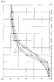
- FIG. 2 shows cumulative curves 2 of particle size analyzes of in in a coordinate system raw gas dust present in various tests, with the Grain size classes of the gas particles in ⁇ m, and the cumulative ones on the ordinate Concentrations of the respective grain size classes are plotted in percent. Like from the Curves can be seen, the majority of the particles lie in a comb band 0.03 ⁇ m and 4.0 ⁇ m.
- the dust-laden raw gas originating from a sintering plant is first removed by a Washer led. There is a pre-separation of larger particles (> 16 ⁇ m) and one Enrichment or saturation of the gas with steam instead. The fine separation takes place in the wet electrostatic precipitator described above.
Landscapes
- Electrostatic Separation (AREA)
- Treating Waste Gases (AREA)
- Filtering Of Dispersed Particles In Gases (AREA)
- Lasers (AREA)
Abstract
Description
Die Erfindung betrifft ein Verfahren zur Reinigung von staubbeladenen Prozeßabgasen in einem Naßelektrofilter.The invention relates to a method for cleaning dust-laden process exhaust gases in a wet electrostatic precipitator.
Naßelektrofilter sind Aggregate zur Staubabscheidung, welche in zunehmendem Maße zur Feinstaubabscheidung eingesetzt werden. Die Auslegung von Elektrofiltern erfolgt zumeist nach der Deutsch-Gleichung.Wet electrostatic precipitators are aggregates for dust separation, which are increasingly used for Fine dust separation can be used. The design of electrostatic filters is mostly done according to the German equation.
Diese lautet:

Bei den vorgegebenen Randbedingungen Staubabscheidegrad (Crein/Croh) und Abgasmengenstrom V bleibt als Parameter das Produkt aus Wanderungsgeschwindigkeit und Niederschlagselektrodenfläche (w.A), d.h. bei bekannter Wanderungsgeschwindigkeit des abzuscheidenden Staubes kann das Filter, insbesondere die notwendige Niederschlagselektrodenfläche, dimensioniert werden. Die Wanderungsgeschwindigkeit ist im übrigen von mehreren Parametern, wie Staubkorngröße, Staubzusammensetzung und Abgasgeschwindigkeit abhängig.Given the specified boundary conditions of dust separation efficiency (C pure / C raw ) and exhaust gas volume flow V, the product of the migration speed and the precipitation electrode area (wA) remains as a parameter, i.e. if the migration speed of the dust to be separated is known, the filter, in particular the necessary precipitation electrode area, can be dimensioned. The speed of migration is also dependent on several parameters, such as dust particle size, dust composition and exhaust gas speed.
Nach dem in der Literatur (Weber, E.; Brocke, W.; Apparate und Verfahren der industriellen Gasreinigung; Bd. 1; S. 352 - 353, sowie Parker K.R.; Applied Electrostatic Precipitation; 1st Edition; 1997; S. 128) beschriebenen theoretischen Modell erreicht man die maximale Wanderungsgeschwindigkeit bei Elektrofiltern bei Abgasströmungsgeschwindigkeiten im Bereich von 2,0 m/s bis 2,5 m/s. Bei höheren Gasgeschwindigkeiten tritt zunehmend Wiederaufwirbelung von bereits an der Niederschlagselektrode abgeschiedenen Partikeln auf und die Wanderungsgeschwindigkeit und damit der Abscheidegrad sinken.According to the in the literature (Weber, E .; Brocke, W .; apparatus and processes of industrial Gas cleaning; Vol. 1; Pp. 352 - 353, and Parker K.R .; Applied Electrostatic Precipitation; 1st Edition; 1997; P. 128) described theoretical model one reaches the maximum Migration speed with electrostatic precipitators at exhaust gas flow speeds in Range from 2.0 m / s to 2.5 m / s. At higher gas speeds occurs increasingly Re-whirling up particles already deposited on the precipitation electrode and the rate of migration and thus the degree of separation decrease.
Bei Naßelektrofiltern existiert im Gegensatz zum trockenen Elektrofilter das Problem, daß bei höheren Abgasgeschwindigkeiten bereits abgeschiedener Staub wieder aufgewirbelt wird, praktisch nicht. Die Aufwärtsbewegung des Wandfilms tritt erst bei sehr hohen Abgasgeschwindigkeiten im Bereich von über 10 m/s auf. Der Austrag von Tropfen durch Ablösung aus dem Wandfilm ist theoretisch und je nach Wasserfilmdicke auch schon bei wesentlich geringeren Abgasgeschwindigkeiten möglich, trägt jedoch aufgrund der höchst wahrscheinlichen Wiederabscheidung der herausgelösten Tropfen nicht wesentlich zum Partikelaustrag bei.In the case of wet electrostatic filters, in contrast to the dry electrostatic precipitator, there is the problem that dust that has already separated out is whirled up again at higher exhaust gas speeds, practically not. The upward movement of the wall film only occurs at very high Exhaust gas speeds in the range of over 10 m / s. The discharge of drops through Detachment from the wall film is theoretical and depending on the thickness of the water film, it is also possible much lower exhaust gas speeds possible, but contributes to the highest probable redeposition of the extracted drops is not essential for Particle discharge at.
Es ist weiters aus der Literatur bekannt (s. Weber, E.; S. 360), daß die mittlere effektive Wanderungsgeschwindigkeit mit zunehmender Staubfeinheit sinkt.It is also known from the literature (see Weber, E .; p. 360) that the mean effective Migration speed decreases with increasing dust fineness.
Naßelektrofilter werden üblicherweise auf Abgasströmungsgeschwindigkeiten von 1,5 m/s bis 2 m/s ausgelegt. Dabei ergeben sich beispielsweise für die Sinteranlagenentstaubung wegen der kleinen Partikelgrößen Wanderungsgeschwindigkeiten auf der Niederschlagselektrodenfläche von ca. 10 cm/s. Diese niedrige Abgasgeschwindigkeit bedingt einen erhöhten Aufwand für Strömungsverteilungseinrichtungen ein- und austrittsseitig im Filter zur Vergleichmäßigung der Abgasströmung. So treten innerhalb von Abgaskanälen vor und nach dem Filter üblicherweise Abgasströmungsgeschwindigkeiten in der Größenordnung von etwa 20 m/s auf. Dies bedeutet eine Beschleunigung austrittsseitig des Filters, bzw. eine Verzögerung eintrittsseitig des Filters um jeweils eine Faktor von ca. 10-13.Wet electrostatic precipitators are typically operated at exhaust gas flow rates of 1.5 m / s 2 m / s designed. This results, for example, for the sintering plant dedusting because of the small particle sizes migration speeds on the precipitation electrode surface of approx. 10 cm / s. This low exhaust gas velocity requires an increased effort for Flow distribution devices on the inlet and outlet sides in the filter to even out the Exhaust gas flow. So usually occur within exhaust gas channels before and after the filter Exhaust gas flow rates on the order of about 20 m / s. this means an acceleration on the outlet side of the filter or a deceleration on the inlet side of the filter by a factor of approx. 10-13 each.
Die Aufgabe der Erfindung besteht nun darin, ein Verfahren zur Reinigung von staubbelasteten Abgasen in einem Naßelektrofilter bereitzustellen, welches dadurch gekennzeichnet ist, daß die Abgasströmungsgeschwindigkeit auf einen Wert eingestellt wird, so daß eine möglichst hohe Wanderungsgeschwindigkeit auftritt und gleichzeitig die Nachteile des Standes der Technik, insbesondere aufwendige Strömungsvergleichmäßigungseinrichtungen und große Niederschlagselektrodenflächen, vermieden werden.The object of the invention is now a method for cleaning dust-laden Provide exhaust gases in a wet electrostatic precipitator, which is characterized in that the Exhaust gas flow rate is set to a value so that the highest possible Migration speed occurs and at the same time the disadvantages of the prior art, especially complex flow equalization devices and large Precipitation electrode surfaces can be avoided.
Unter Naßelektrofiltem im Sinne der Erfindung werden dabei sowohl solche verstanden, bei denen das Abgas vor Eintritt in den Filter völlig oder fast völlig mit Wasserdampf gesättigt, als auch solche, bei denen das Abgas bei Eintritt in den Filter eine deutliche Untersättigung an Wasserdampf aufweist. Bei letzteren Naßelektrofiltern muß daher die Abreinigung der Niederschlagselektroden durch zusätzliche Wassereindüsung geschehen.In the context of the invention, wet electrostatic filters are understood to mean both such where the exhaust gas is fully or almost completely saturated with water vapor before entering the filter even those in which the exhaust gas shows a significant undersaturation when entering the filter Has water vapor. In the latter wet electrostatic filters, the cleaning of the Precipitation electrodes happen by additional water injection.
Diese Aufgabe wird durch die gegenständliche Erfindung gelöst, welche dadurch gekennzeichnet ist, daß die Abgasströmungsgeschwindigkeit auf einen Wert von 4 m/s bis 9 m/s eingestellt wird. Durch die Erhöhung der Strömungsgeschwindigkeit in diesen Bereich erhöht sich die Wanderungsgeschwindigkeit der Partikel gegenüber den Wanderungsgeschwindigkeiten bei derzeit üblichen Abgaströmungsgeschwindigkeiten von 1,5 m/s bis 2 m/s bei Naßelektrofiltern im Fall der Sinteranlagenentstaubung von etwa 10 cm/s auf über 40 cm/s.This object is achieved by the subject invention, which thereby is characterized in that the exhaust gas flow rate to a value of 4 m / s to 9 m / s is set. By increasing the flow velocity in this area the migration speed of the particles increases compared to Migration speeds at current exhaust gas flow speeds of 1.5 m / s to 2 m / s for wet electrostatic precipitators in the case of sintering system dedusting of approximately 10 cm / s over 40 cm / s.
Dadurch kann bei gleichbleibendem Wirkungsgrad die Niederschlagselektrodenfläche und damit auch das Gewicht der Niederschlagselektrode im Verhältnis zur Steigerung der Wanderungsgeschwindigkeit verringert werden. Weiters wird der Aufwand für Strömungsvergleichmäßigungseinrichtungen ein- und austrittsseitig des Filters somit minimiert (Verzögerung bzw. Beschleunigung nur mehr um einen Faktor von ca. 2-5). Das Naßelektrofilter wird dadurch entsprechend verkleinert, wodurch auch die Investitionskosten geringer ausfallen.As a result, the precipitation electrode area and hence the weight of the precipitation electrode in relation to the increase in Migration speed can be reduced. Furthermore, the effort for Flow equalization devices on the inlet and outlet sides of the filter are thus minimized (Deceleration or acceleration only by a factor of approx. 2-5). The Wet electrostatic precipitator is reduced accordingly, which also means the investment costs turn out to be lower.
Die Erfindung wird nun anhand der Zeichnungen 1 und 2 näher erläutert.
In der Fig. 1 sind in einem Koordinatensystem Meßpunkte 1, die bei Versuchen ermittelt wurden, dargestellt, wobei auf der Abszisse die Abgasströmungsgeschwindigkeit in m/s und auf der Ordinate die Wanderungsgeschwindigkeit der Partikel in cm/s aufgetragen ist.1 there are measuring points 1 in a coordinate system, which are determined during tests were shown, with the exhaust gas flow velocity in m / s and the migration speed of the particles in cm / s is plotted on the ordinate.
Wie ersichtlich, steigt die Wanderungsgeschwindigkeit bis zu Abgasgeschwindigkeiten von ca. 6 m/s etwa linear an, bei höheren Geschwindigkeiten macht sich eine Abflachung der Kurve bemerkbar. Im erfindungsgemäßen Bereich von 4 m/s bis 9 m/s tritt noch kaum unerwünschte Tropfenablösung auf.As can be seen, the migration speed increases up to exhaust gas speeds of approx. 6 m / s approximately linear, at higher speeds the curve flattens out noticeable. In the range from 4 m / s to 9 m / s according to the invention, there are hardly any undesirable effects Drop detachment.
Fig. 2 zeigt in einem Koordinatensystem Summenkurven 2 von Teilchengrößenanalysen von in
verschiedenen Versuchen vorliegenden Rohgasstäuben, wobei auf der Abszisse die
Korngrößenklassen der Gaspartikel in µm, und auf der Ordinate die kumulierten
Konzentrationen der jeweiligen Korngrößenklassen in Prozent aufgetragen sind. Wie aus den
Kurven ersichtlich ist, liegt der überwiegende Anteil der Partikel in einem Komband zwischen
0,03 µm und 4,0 µm vor.FIG. 2 shows
Die Versuche, die zu den in Fig. 1 und Fig. 2 gezeigten Meßpunkten führten, wurden in einem
Naßelektrofilter folgenden Aufbaus durchgeführt:
Das aus einer Sinteranlage stammende staubbeladene Rohgas wird zunächst durch einen Wäscher geführt. Es findet dabei eine Vorabscheidung größerer Partikel (> 16 µm) sowie eine Anreicherung bzw. Sättigung des Gases mit Wasserdampf statt. Die Feinabscheidung erfolgt im oben beschriebenen Naßelektrofilter.The dust-laden raw gas originating from a sintering plant is first removed by a Washer led. There is a pre-separation of larger particles (> 16 µm) and one Enrichment or saturation of the gas with steam instead. The fine separation takes place in the wet electrostatic precipitator described above.
Claims (6)
- Method for cleaning steam-containing, dust-laden processed gases in a wet electrostatic filter, in which preliminary separation of relatively large dust particles, in particular of dust with a particle size of more than 16 µm, and an increase in the levels or saturation of the processed gases with steam is carried out in a scrubber, and in which the gases or the dust particles contained therein, which then flow through the wet electrostatic filter, are charged in a space between one or more discharge electrodes and one or more collecting electrodes and are precipitated on the collecting electrode(s), characterized in that the off-gas flow velocity through the wet electrostatic filter is set to a value of from 4 m/s to 9 m/s, the wet electrostatic filter separating out all the rest of the dust in the region of the collecting electrodes, which have a length which is sufficient for this purpose.
- Method according to Claim 1, characterized in that the off-gas flow velocity through the wet electrostatic filter is set to a value of from 4.5 m/s to 9 m/s.
- Method according to Claim 2, characterized in that the off-gas flow velocity through the wet electrostatic filter is set to a value of from 5 m/s to 9 m/s.
- Method according to one of Claims 1 to 3, characterized in that at least 90% of the fine dust which is to be separated out comprises particles of a particle size of up to 4 µm.
- Method according to one of Claims 1 to 4, characterized in that at least 80% of the total amount of particles of the dust which is to be separated out lies within a grain size range of from 0.03 µm to 2.0 µm.
- Method according to one of Claims 1 to 6, characterized in that the discharge electrode used is a rod-like electrode.
Applications Claiming Priority (3)
| Application Number | Priority Date | Filing Date | Title |
|---|---|---|---|
| AT62197 | 1997-04-11 | ||
| AT0062197A ATA62197A (en) | 1997-04-11 | 1997-04-11 | METHOD FOR PURIFYING DUST-LOADED PROCESS EXHAUST GASES |
| PCT/AT1998/000088 WO1998046359A1 (en) | 1997-04-11 | 1998-04-03 | Method for cleaning waste process gases containing dust |
Publications (2)
| Publication Number | Publication Date |
|---|---|
| EP0973615A1 EP0973615A1 (en) | 2000-01-26 |
| EP0973615B1 true EP0973615B1 (en) | 2002-07-31 |
Family
ID=3495450
Family Applications (1)
| Application Number | Title | Priority Date | Filing Date |
|---|---|---|---|
| EP98912138A Expired - Lifetime EP0973615B1 (en) | 1997-04-11 | 1998-04-03 | Method for cleaning waste process gases containing dust |
Country Status (6)
| Country | Link |
|---|---|
| EP (1) | EP0973615B1 (en) |
| CN (1) | CN1252016A (en) |
| AT (2) | ATA62197A (en) |
| AU (1) | AU735231B2 (en) |
| DE (1) | DE59805002D1 (en) |
| WO (1) | WO1998046359A1 (en) |
Family Cites Families (1)
| Publication number | Priority date | Publication date | Assignee | Title |
|---|---|---|---|---|
| DE3329638A1 (en) * | 1983-08-17 | 1985-03-07 | Gottfried Bischoff Bau kompl. Gasreinigungs- und Wasserrückkühlanlagen GmbH & Co KG, 4300 Essen | DEVICE FOR THE DEDUSTING OF INDUSTRIAL GASES |
-
1997
- 1997-04-11 AT AT0062197A patent/ATA62197A/en not_active Application Discontinuation
-
1998
- 1998-04-03 EP EP98912138A patent/EP0973615B1/en not_active Expired - Lifetime
- 1998-04-03 AT AT98912138T patent/ATE221416T1/en not_active IP Right Cessation
- 1998-04-03 AU AU67116/98A patent/AU735231B2/en not_active Ceased
- 1998-04-03 WO PCT/AT1998/000088 patent/WO1998046359A1/en active IP Right Grant
- 1998-04-03 DE DE59805002T patent/DE59805002D1/en not_active Expired - Fee Related
- 1998-04-03 CN CN98804050.6A patent/CN1252016A/en active Pending
Also Published As
| Publication number | Publication date |
|---|---|
| ATA62197A (en) | 2000-07-15 |
| CN1252016A (en) | 2000-05-03 |
| WO1998046359A1 (en) | 1998-10-22 |
| AU6711698A (en) | 1998-11-11 |
| EP0973615A1 (en) | 2000-01-26 |
| ATE221416T1 (en) | 2002-08-15 |
| AU735231B2 (en) | 2001-07-05 |
| DE59805002D1 (en) | 2002-09-05 |
Similar Documents
| Publication | Publication Date | Title |
|---|---|---|
| EP0185966B1 (en) | Process and device for cleaning a gas stream containing solid or liquid particles in suspension | |
| EP0461695B1 (en) | Process and apparatus for cleaning dust-laden and noxious exhaust gases | |
| DE3122515C2 (en) | Electrostatic filter assembly | |
| EP0092854B1 (en) | Wet electrofilter for a converter exhaust | |
| DE2838159A1 (en) | METHOD AND DEVICE FOR TREATING GASES LOADED WITH DIRTY PARTICLES | |
| AT408843B (en) | DUST FILTER | |
| EP2042244A2 (en) | Method and device for removing dust and/or fibrous products from a plastic granulate | |
| EP0973615B1 (en) | Method for cleaning waste process gases containing dust | |
| DE102006033945C5 (en) | Controlling the high voltage of an electric air filter device | |
| DE3716126A1 (en) | DUST DISPENSER DEVICE | |
| DE2307508A1 (en) | ELECTRIC FAILURE DEVICE | |
| CH623240A5 (en) | ||
| CH636778A5 (en) | METHOD AND DEVICE FOR SEPARATING FINE DUST AND AEROSOLS FROM A GAS FLOW. | |
| EP0594916B1 (en) | Method and device for cleaning of surfaces, in particular for masonry | |
| DE2216436A1 (en) | Dust filter device | |
| DE4018488C1 (en) | Removing dust and hazardous materials from waste gases - by sepg. dust in dry multi-cyclone stage, and wet electrostatic precipitator stage | |
| DE2846499A1 (en) | METHOD FOR REMOVING DUST PARTICLES THEREOF WITH LEADING PARTICLES | |
| EP0545943B1 (en) | Process and plant for separating solid and/or liquid and/or gaseous particles from a gas stream | |
| DE10124871C1 (en) | Device used for removing particles from gas stream comprises plate-like passive electrode with surface for collecting particles, and operating unit interacting with electrode and producing low frequency oscillation | |
| DE202005012277U1 (en) | Dust collecting device used in iron and steel industry and in cement production for removing dust from gaseous materials comprises electro-filter and fabric filter arranged between gas inlet support and gas outlet support | |
| EP0658380A1 (en) | Device for separating dust particles from exhaust gases | |
| DE2235531B2 (en) | Method and device for separating extremely fine foreign matter particles from a gas flow | |
| DE102015016554A1 (en) | Device for separating overspray, surface treatment system and method for separating overspray | |
| EP2399660A2 (en) | Particle impact separator | |
| DE10162053B4 (en) | separation processes |
Legal Events
| Date | Code | Title | Description |
|---|---|---|---|
| PUAI | Public reference made under article 153(3) epc to a published international application that has entered the european phase |
Free format text: ORIGINAL CODE: 0009012 |
|
| 17P | Request for examination filed |
Effective date: 19990820 |
|
| AK | Designated contracting states |
Kind code of ref document: A1 Designated state(s): AT BE DE GB IT |
|
| GRAG | Despatch of communication of intention to grant |
Free format text: ORIGINAL CODE: EPIDOS AGRA |
|
| GRAG | Despatch of communication of intention to grant |
Free format text: ORIGINAL CODE: EPIDOS AGRA |
|
| GRAH | Despatch of communication of intention to grant a patent |
Free format text: ORIGINAL CODE: EPIDOS IGRA |
|
| 17Q | First examination report despatched |
Effective date: 20020131 |
|
| GRAH | Despatch of communication of intention to grant a patent |
Free format text: ORIGINAL CODE: EPIDOS IGRA |
|
| GRAA | (expected) grant |
Free format text: ORIGINAL CODE: 0009210 |
|
| AK | Designated contracting states |
Kind code of ref document: B1 Designated state(s): AT BE DE GB IT |
|
| REF | Corresponds to: |
Ref document number: 221416 Country of ref document: AT Date of ref document: 20020815 Kind code of ref document: T |
|
| REG | Reference to a national code |
Ref country code: GB Ref legal event code: FG4D Free format text: NOT ENGLISH |
|
| REF | Corresponds to: |
Ref document number: 59805002 Country of ref document: DE Date of ref document: 20020905 |
|
| GBT | Gb: translation of ep patent filed (gb section 77(6)(a)/1977) |
Effective date: 20021104 |
|
| PLBE | No opposition filed within time limit |
Free format text: ORIGINAL CODE: 0009261 |
|
| STAA | Information on the status of an ep patent application or granted ep patent |
Free format text: STATUS: NO OPPOSITION FILED WITHIN TIME LIMIT |
|
| 26N | No opposition filed |
Effective date: 20030506 |
|
| PGFP | Annual fee paid to national office [announced via postgrant information from national office to epo] |
Ref country code: GB Payment date: 20040331 Year of fee payment: 7 |
|
| PGFP | Annual fee paid to national office [announced via postgrant information from national office to epo] |
Ref country code: AT Payment date: 20040405 Year of fee payment: 7 |
|
| PGFP | Annual fee paid to national office [announced via postgrant information from national office to epo] |
Ref country code: DE Payment date: 20040408 Year of fee payment: 7 |
|
| PGFP | Annual fee paid to national office [announced via postgrant information from national office to epo] |
Ref country code: BE Payment date: 20040527 Year of fee payment: 7 |
|
| PG25 | Lapsed in a contracting state [announced via postgrant information from national office to epo] |
Ref country code: IT Free format text: LAPSE BECAUSE OF NON-PAYMENT OF DUE FEES;WARNING: LAPSES OF ITALIAN PATENTS WITH EFFECTIVE DATE BEFORE 2007 MAY HAVE OCCURRED AT ANY TIME BEFORE 2007. THE CORRECT EFFECTIVE DATE MAY BE DIFFERENT FROM THE ONE RECORDED. Effective date: 20050403 Ref country code: GB Free format text: LAPSE BECAUSE OF NON-PAYMENT OF DUE FEES Effective date: 20050403 Ref country code: AT Free format text: LAPSE BECAUSE OF NON-PAYMENT OF DUE FEES Effective date: 20050403 |
|
| PG25 | Lapsed in a contracting state [announced via postgrant information from national office to epo] |
Ref country code: BE Free format text: LAPSE BECAUSE OF NON-PAYMENT OF DUE FEES Effective date: 20050430 |
|
| BERE | Be: lapsed |
Owner name: *VOEST-ALPINE INDUSTRIEANLAGENBAU G.M.B.H. Effective date: 20050430 |
|
| PG25 | Lapsed in a contracting state [announced via postgrant information from national office to epo] |
Ref country code: DE Free format text: LAPSE BECAUSE OF NON-PAYMENT OF DUE FEES Effective date: 20051101 |
|
| GBPC | Gb: european patent ceased through non-payment of renewal fee |
Effective date: 20050403 |
|
| BERE | Be: lapsed |
Owner name: *VOEST-ALPINE INDUSTRIEANLAGENBAU G.M.B.H. Effective date: 20050430 |