EP0973402B1 - Mill, in particular for milling of bone, as well as a drum, provided with cutting members, applicable in the mill - Google Patents
Mill, in particular for milling of bone, as well as a drum, provided with cutting members, applicable in the mill Download PDFInfo
- Publication number
- EP0973402B1 EP0973402B1 EP98903290A EP98903290A EP0973402B1 EP 0973402 B1 EP0973402 B1 EP 0973402B1 EP 98903290 A EP98903290 A EP 98903290A EP 98903290 A EP98903290 A EP 98903290A EP 0973402 B1 EP0973402 B1 EP 0973402B1
- Authority
- EP
- European Patent Office
- Prior art keywords
- drum
- cutting members
- mill
- mill according
- cutting
- Prior art date
- Legal status (The legal status is an assumption and is not a legal conclusion. Google has not performed a legal analysis and makes no representation as to the accuracy of the status listed.)
- Expired - Lifetime
Links
- 238000005520 cutting process Methods 0.000 title claims description 78
- 210000000988 bone and bone Anatomy 0.000 title claims description 31
- 238000003801 milling Methods 0.000 title claims description 9
- 239000000463 material Substances 0.000 claims description 7
- 230000008719 thickening Effects 0.000 claims description 5
- 238000003754 machining Methods 0.000 claims description 4
- 238000004519 manufacturing process Methods 0.000 description 8
- 230000004323 axial length Effects 0.000 description 2
- 230000007547 defect Effects 0.000 description 2
- 206010011732 Cyst Diseases 0.000 description 1
- 206010028980 Neoplasm Diseases 0.000 description 1
- 238000005452 bending Methods 0.000 description 1
- 238000005266 casting Methods 0.000 description 1
- 238000004140 cleaning Methods 0.000 description 1
- 208000031513 cyst Diseases 0.000 description 1
- 230000004927 fusion Effects 0.000 description 1
- 238000000227 grinding Methods 0.000 description 1
- 239000002184 metal Substances 0.000 description 1
- 238000000034 method Methods 0.000 description 1
- 239000002245 particle Substances 0.000 description 1
- 239000004033 plastic Substances 0.000 description 1
- 229920003023 plastic Polymers 0.000 description 1
- 239000002023 wood Substances 0.000 description 1
Images


Classifications
-
- A—HUMAN NECESSITIES
- A22—BUTCHERING; MEAT TREATMENT; PROCESSING POULTRY OR FISH
- A22C—PROCESSING MEAT, POULTRY, OR FISH
- A22C17/00—Other devices for processing meat or bones
- A22C17/06—Bone-shears; Bone-crushers
-
- A—HUMAN NECESSITIES
- A61—MEDICAL OR VETERINARY SCIENCE; HYGIENE
- A61F—FILTERS IMPLANTABLE INTO BLOOD VESSELS; PROSTHESES; DEVICES PROVIDING PATENCY TO, OR PREVENTING COLLAPSING OF, TUBULAR STRUCTURES OF THE BODY, e.g. STENTS; ORTHOPAEDIC, NURSING OR CONTRACEPTIVE DEVICES; FOMENTATION; TREATMENT OR PROTECTION OF EYES OR EARS; BANDAGES, DRESSINGS OR ABSORBENT PADS; FIRST-AID KITS
- A61F2/00—Filters implantable into blood vessels; Prostheses, i.e. artificial substitutes or replacements for parts of the body; Appliances for connecting them with the body; Devices providing patency to, or preventing collapsing of, tubular structures of the body, e.g. stents
- A61F2/02—Prostheses implantable into the body
- A61F2/30—Joints
- A61F2/46—Special tools or methods for implanting or extracting artificial joints, accessories, bone grafts or substitutes, or particular adaptations therefor
- A61F2/4644—Preparation of bone graft, bone plugs or bone dowels, e.g. grinding or milling bone material
-
- B—PERFORMING OPERATIONS; TRANSPORTING
- B02—CRUSHING, PULVERISING, OR DISINTEGRATING; PREPARATORY TREATMENT OF GRAIN FOR MILLING
- B02C—CRUSHING, PULVERISING, OR DISINTEGRATING IN GENERAL; MILLING GRAIN
- B02C18/00—Disintegrating by knives or other cutting or tearing members which chop material into fragments
- B02C18/06—Disintegrating by knives or other cutting or tearing members which chop material into fragments with rotating knives
- B02C18/16—Details
- B02C18/18—Knives; Mountings thereof
-
- A—HUMAN NECESSITIES
- A61—MEDICAL OR VETERINARY SCIENCE; HYGIENE
- A61F—FILTERS IMPLANTABLE INTO BLOOD VESSELS; PROSTHESES; DEVICES PROVIDING PATENCY TO, OR PREVENTING COLLAPSING OF, TUBULAR STRUCTURES OF THE BODY, e.g. STENTS; ORTHOPAEDIC, NURSING OR CONTRACEPTIVE DEVICES; FOMENTATION; TREATMENT OR PROTECTION OF EYES OR EARS; BANDAGES, DRESSINGS OR ABSORBENT PADS; FIRST-AID KITS
- A61F2/00—Filters implantable into blood vessels; Prostheses, i.e. artificial substitutes or replacements for parts of the body; Appliances for connecting them with the body; Devices providing patency to, or preventing collapsing of, tubular structures of the body, e.g. stents
- A61F2/02—Prostheses implantable into the body
- A61F2/28—Bones
- A61F2002/2835—Bone graft implants for filling a bony defect or an endoprosthesis cavity, e.g. by synthetic material or biological material
-
- A—HUMAN NECESSITIES
- A61—MEDICAL OR VETERINARY SCIENCE; HYGIENE
- A61F—FILTERS IMPLANTABLE INTO BLOOD VESSELS; PROSTHESES; DEVICES PROVIDING PATENCY TO, OR PREVENTING COLLAPSING OF, TUBULAR STRUCTURES OF THE BODY, e.g. STENTS; ORTHOPAEDIC, NURSING OR CONTRACEPTIVE DEVICES; FOMENTATION; TREATMENT OR PROTECTION OF EYES OR EARS; BANDAGES, DRESSINGS OR ABSORBENT PADS; FIRST-AID KITS
- A61F2/00—Filters implantable into blood vessels; Prostheses, i.e. artificial substitutes or replacements for parts of the body; Appliances for connecting them with the body; Devices providing patency to, or preventing collapsing of, tubular structures of the body, e.g. stents
- A61F2/02—Prostheses implantable into the body
- A61F2/30—Joints
- A61F2/46—Special tools or methods for implanting or extracting artificial joints, accessories, bone grafts or substitutes, or particular adaptations therefor
- A61F2/4644—Preparation of bone graft, bone plugs or bone dowels, e.g. grinding or milling bone material
- A61F2002/4645—Devices for grinding or milling bone material
Definitions
- the invention relates to a mill, in particular for milling of bone, comprising a housing provided with at least one opening, for supply of material to be milled and removal of machined chips, and a drum, provided with cutting members, which is rotatably located inside the housing.
- a mill is eg. known from FR-A-1 094 782.
- chips can be made, such as machining, cutting, chipping, morselizing, breaking, chopping.
- chips all kind of small particles are meant like e.g. splinters, flakes, pieces, slices.
- cutting members all kind of tools, such as for example knives, chisels and teeth are meant, which can be used to mill a material.
- the milling of bone is a known method in the medical field, where bone chips are used for the filling of defects in bones, which are created by the removal of a tumor or cyst, or are used for filling a gap between a prosthetic stem or cup and the surrounding bone of a patient in case of a revision operation, where inevitably part of the original bone stock has been lost. Further more bone chips are used among others for the correction of deviant bony structures, so called bone plasties, for the correction of fracture defects and for fusion of joints and vertebrae. Bone chips are not rejected by the human body and they integrate with the natural existing bone.
- a mill of the type mentioned at the beginning is disclosed in the Swedish patent number 9402781-0.
- the bone mill described inhere has a drum provided with a number of axially elongated grooves, in which cutting blocks are seated which are removably attached to the drum and all grooves are extended in one straight line parallel to the axial direction.
- the separate manufacturing of the drum and the cutting blocks is an expensive method of manufacturing. Because the cutting blocks are located in one straight line and because all cutting edges of one cutting block are located in one straight line, all cutting members of one cutting block come simultaneously into contact with the bone to be milled. This results in a jerkily action and an inefficient milling process.
- a similar prementioned mill is also generally known, at least in the medical field, as a mill with a drum provided with round openings which are formed by bending parts of the wall of the drum outwards and grinding cutting edges on them. Due to the shape of the cutting edges, a larger force to produce the desired large size of chips is needed than with the aforementioned known bone mill. For these reasons the milling process takes more time and effort than with the aforementioned known bone mill.
- An object of the invention is to provide a mill which is less expensive to manufacture than the known bone mills. Therefore the mill of the present invention is characterized in that the cutting members are formed by local thickenings of the wall of the drum. By manufacturing the drum and the cutting members from one piece, the cleaning procedure in the field is simpler and the number of manufacturing steps can be reduced by simultaneous manufacturing of the drum and the cutting members.
- a preferred embodiment of the mill according to this invention is characterized in that the cutting members are provided with a cutting edge which with one point protrudes in the circumferential direction of the drum, such that during operation the cutting members will contact with this point first the material to be milled. As the cutting members do not contact the bone at their full width less force is needed and the force increases more gradually which makes the mill work more efficiently than the known bone mill.
- This design feature can also be applied seperately without that the drum and cutting members are made from one piece and the cutting members are formed by local thickenings of the wall of the drum. For example by attaching seperate cutting members to the drum.
- a further embodiment is characterized in that at least part of the cutting members are mutually displaced in the axial direction of the drum.
- One embodiment which can be efficiently manufactured is characterized in that at least part of the cutting members are located along an imaginary spiralled line around the drum. Such a configuration can relativily easily be realized on a lathe.
- a further embodiment is characterized in that at least part of the cutting members are mutually displaced in the circumferential direction of the drum. Because of this, only one or a few cutting members contact the bone at the same moment. It is noted that also this design feature can be applied seperately without that the drum and cutting members are made from one piece and the cutting members are formed by local thickenings of the wall of the drum and also without that the cutting members protrude with one point in the circumferential direction.
- a practical advantageous embodiment is characterized in that at least part of the cutting members are located along a number of imaginary oblique lines which run at an angle with the axial direction of the drum.
- a practical embodiment at which both aforementioned configurations can be manufactured efficiently is characterized in that at least part of the cutting members are located at the intersections of the imaginary oblique lines and the imaginary spiralled line.
- a further embodiment is characterized in that aside the imaginary oblique lines, in front of the cutting members as viewed in the direction of rotation elongated slots are present.
- a preferred embodiment of the mill according to the invention which can practically advantageous be manufactured is characterized in that the drum with the cutting members is formed by machining the outer surface of a thick-walled drum, such that on the outer surface of that drum a spiralshaped rim remains which is removed at a number of places and at the remaining parts cutting edges and clearance surfaces are machined.
- the invention also relates to a drum provided with cutting members applicable in the mill according to the invention.
- Drums with cutting members can also be marketed seperately and are of course exchangeable. Therefore various drums with different numbers and sizes of cutting members can go with one housing to produce bone chips of various sizes.
- FIG 1 a mill according to the invention is shown.
- the mill 1 has a cylindrical housing 3 which can by means of a footh 5 be placed on for example a table.
- the mill 1 can be fastened to the table by a fastening clamp 7 which is attached to footh 5.
- a supply opening 9 is located in housing 3 for the supply of bone to be milled.
- a funnel 11 is located on the housing 3.
- the cylindrical housing 3 is open at one end. This opening 13 serves for the introduction of a drum 15 with cutting members 17 in the housing 3. This drum 15 is also provided with an opening 19 at one end for the removal of machined chips.
- a hexagonal shaft 21 is located, which is pushed through another opening 23 located in the housing 3, and to which a handle 25 is attached.
- a threaded end 27 is attached to the end of the hexagonal shaft 21 .
- the drum 15 is supported by two bearing bushes 30 and 31 in housing 3. Inside the funnel 11 a push block 32 is located inside the funnel 11 . This push block 32 is located inside the funnel 11 . This push block 32 is formed by a piece of metal which is placed on top of the bone in tunnel 11 and with which the bone can be pushed downwards.
- the drum 15 can easily be taken out of housing 3 by unscrewing nut 29 and can then be exchanged for another drum with for example less but larger cutting members. This is in particular handy if various sizes of bone chips are needed.
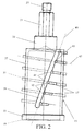
- the drum 15 is shown alone. At one end the drum is provided with the said opening 19 and at the other end the hexagonal shaft 21 with threaded end 27 is located. At both ends the drum 15 is provided with bearing surfaces 33 and 35 which coincide with the bearing bushes 30 and 31 in the housing 3.
- the cutting members 17 are located on the drum 15 .
- the drum 15 and the cutting members 17 are made from one piece at which the cutting members 17 are formed by local thickenings of the wall 37 of the drum. Further elongated slots 39 are located in the wall 37 of the drum, in front of the cutting members 17 as viewed in the direction of rotation, through which bone chips can pass during operation.
- the cutting members 17 are provided with a cutting edge 41 which with one point 43 protrude in the circumferential direction of the drum, such that during operation the cutting members 17 contact the material to be milled with this point 43 first.
- the cutting members 17 are located at the intersections 45 of an imaginary spiralled line 47 around the drum and a number imaginary oblique lines 49, which run at an angle with the axial direction of the drum. Thereby the cutting members 17 are mutually displaced in the axial and the circumferential direction of the drum.
- the pitch angle of the imaginary spiralled line 47, the number of rows of the cutting members 17 and the width of the cutting members are adjusted such that during one revolution of the drum 15 over the full axial length of the supply opening 19 at least one cutting member 17 has passed, such that the bones to be milled in the supply opening have one continuous layer of bone removed.
- the drum 15 and the cutting members 17 are formed by machining the outer surface of a thick-walled drum, such that on the outer surface of that drum 17 a spiralshaped rim 51 remains (shown with dotted lines) which is then removed at a number of places. At the remaining parts cutting edges 41 and clearance surfaces 53 (see figure 3) are machined which form the cutting members. If required these can be hardened.
- figure 3 shows a cross-section of drum 15 along an imaginary spiralled line 47. For easy reference only one row of cutting members is shown in figure 2. In reality more cutting members would been shown.
- the exterior of the mill can be designed differently, for example by using an electric or pneumatic motor in stead of a hand driven handle or by situating the opening for removal of chips in the bottom of the housing.
- the manufacturing of the drum with cutting members can also be acomplished in another fashion, like for example casting followed by finishing of the cutting edges.
- the cutting members can, instead of along one spiralled line, be located along several spiralled lines.
- the mill is not only suitable for milling of bone but can also be used for milling of other materials such as wood and plastics.
Landscapes
- Health & Medical Sciences (AREA)
- Engineering & Computer Science (AREA)
- Life Sciences & Earth Sciences (AREA)
- Orthopedic Medicine & Surgery (AREA)
- Transplantation (AREA)
- Food Science & Technology (AREA)
- Oral & Maxillofacial Surgery (AREA)
- Vascular Medicine (AREA)
- Zoology (AREA)
- Cardiology (AREA)
- Wood Science & Technology (AREA)
- Biomedical Technology (AREA)
- Heart & Thoracic Surgery (AREA)
- Physical Education & Sports Medicine (AREA)
- Animal Behavior & Ethology (AREA)
- General Health & Medical Sciences (AREA)
- Public Health (AREA)
- Veterinary Medicine (AREA)
- Surgical Instruments (AREA)
- Crushing And Pulverization Processes (AREA)
Applications Claiming Priority (3)
| Application Number | Priority Date | Filing Date | Title |
|---|---|---|---|
| NL1005251 | 1997-02-11 | ||
| NL1005251A NL1005251C2 (nl) | 1997-02-11 | 1997-02-11 | Versnipperaar, in het bijzonder voor het versnipperen van bot, alsmede trommel voorzien van versnipperorganen toepasbaar in de versnipperaar. |
| PCT/NL1998/000081 WO1998034491A1 (en) | 1997-02-11 | 1998-02-10 | Mill, in particular for milling of bone, as well as a drum, provided with cutting members, applicable in the mill |
Publications (2)
| Publication Number | Publication Date |
|---|---|
| EP0973402A1 EP0973402A1 (en) | 2000-01-26 |
| EP0973402B1 true EP0973402B1 (en) | 2002-12-11 |
Family
ID=19764403
Family Applications (1)
| Application Number | Title | Priority Date | Filing Date |
|---|---|---|---|
| EP98903290A Expired - Lifetime EP0973402B1 (en) | 1997-02-11 | 1998-02-10 | Mill, in particular for milling of bone, as well as a drum, provided with cutting members, applicable in the mill |
Country Status (7)
| Country | Link |
|---|---|
| US (1) | US6318651B1 (nl) |
| EP (1) | EP0973402B1 (nl) |
| AU (1) | AU6006098A (nl) |
| DE (1) | DE69810092T2 (nl) |
| ES (1) | ES2187925T3 (nl) |
| NL (1) | NL1005251C2 (nl) |
| WO (1) | WO1998034491A1 (nl) |
Cited By (1)
| Publication number | Priority date | Publication date | Assignee | Title |
|---|---|---|---|---|
| CN102869264A (zh) * | 2010-01-07 | 2013-01-09 | 美敦力施美德公司 | 骨处理系统和方法 |
Families Citing this family (23)
| Publication number | Priority date | Publication date | Assignee | Title |
|---|---|---|---|---|
| RU2162410C1 (ru) * | 2000-07-13 | 2001-01-27 | Харина Рита Адамовна | Устройство для обработки и переработки материалов |
| US7582092B2 (en) | 2003-06-25 | 2009-09-01 | Depuy Products, Inc. | Assembly tool for modular implants and associated method |
| US7074224B2 (en) | 2003-06-25 | 2006-07-11 | Depuy Products, Inc. | Modular tapered reamer for bone preparation and associated method |
| US8998919B2 (en) | 2003-06-25 | 2015-04-07 | DePuy Synthes Products, LLC | Assembly tool for modular implants, kit and associated method |
| US7297166B2 (en) | 2003-06-25 | 2007-11-20 | Depuy Products, Inc. | Assembly tool for modular implants and associated method |
| US7785328B2 (en) * | 2003-12-30 | 2010-08-31 | Depuy Products, Inc. | Minimally invasive bone miller apparatus |
| US7431230B2 (en) * | 2005-03-16 | 2008-10-07 | Medtronic Ps Medical, Inc. | Apparatus and method for bone morselization for surgical grafting |
| US7588202B2 (en) * | 2006-01-17 | 2009-09-15 | Houshang Rasekhi | Apparatus for milling material |
| US8196850B2 (en) * | 2006-01-17 | 2012-06-12 | Houshang Rasekhi | Self-clearing rasp system for automatic milling apparatus |
| US8597298B2 (en) | 2006-09-29 | 2013-12-03 | DePuy Synthes Products, LLC | Proximal reamer |
| US8556912B2 (en) | 2007-10-30 | 2013-10-15 | DePuy Synthes Products, LLC | Taper disengagement tool |
| US8518050B2 (en) | 2007-10-31 | 2013-08-27 | DePuy Synthes Products, LLC | Modular taper assembly device |
| US8002774B2 (en) | 2007-11-07 | 2011-08-23 | Stryker Corporation | Bone mill including a base and a mill head separate from the base, the mill head including a moveable catch tray |
| EP2072139B1 (en) * | 2007-12-21 | 2020-05-13 | Robert Bosch GmbH | Improvements in or relating to shredder cutters |
| US8167882B2 (en) | 2008-09-30 | 2012-05-01 | Depuy Products, Inc. | Minimally invasive bone miller apparatus |
| US8533921B2 (en) | 2010-06-15 | 2013-09-17 | DePuy Synthes Products, LLC | Spiral assembly tool |
| US9095452B2 (en) | 2010-09-01 | 2015-08-04 | DePuy Synthes Products, Inc. | Disassembly tool |
| WO2013115757A2 (en) * | 2010-12-22 | 2013-08-08 | Warsaw Orthopedic, Inc. | Osteobiologic milling machine |
| CN107028688B (zh) | 2011-04-06 | 2018-09-21 | 德普伊新特斯产品有限责任公司 | 植入修正髋关节假体的器械组件 |
| CA2860795C (en) * | 2012-01-13 | 2023-10-03 | Christopher G. Sidebotham | Medical reamers and methods of forming the same |
| US10863993B2 (en) | 2012-01-13 | 2020-12-15 | Christopher G. Sidebotham | System and method for preparing prosthetic hip implantation |
| EP3378445A1 (en) * | 2017-03-23 | 2018-09-26 | Ronvig Dental Mfg. A/S | Bone grinder |
| US11707551B2 (en) * | 2021-10-21 | 2023-07-25 | Metal Industries Research & Development Centre | Implant shredder and implant forming method |
Family Cites Families (7)
| Publication number | Priority date | Publication date | Assignee | Title |
|---|---|---|---|---|
| US2228025A (en) * | 1939-12-11 | 1941-01-07 | Andrew A Apfelbeck | Grater |
| FR1094782A (fr) * | 1954-03-09 | 1955-05-24 | Appareil pour la préparation des viandes amalgamées | |
| FR2201037B1 (nl) * | 1972-09-22 | 1975-06-13 | Schlumberger Cie N | |
| US4061280A (en) * | 1976-10-29 | 1977-12-06 | Box Theodor | Mixing apparatus for feed to injection molding machine |
| DE3807983C2 (de) * | 1988-03-10 | 1999-07-22 | Faller Alexander Maschbau | Vorrichtung zum Zerkleinern |
| DE3808409A1 (de) * | 1988-03-14 | 1989-09-28 | Werner Weinmueller | Knochenmuehle |
| SE503270C2 (sv) * | 1994-08-22 | 1996-04-29 | Harry Wexell | Kvarn, förfarande för tillverkning av bentransplantationsmaterial och användning av kvarn för sådan tillverkning |
-
1997
- 1997-02-11 NL NL1005251A patent/NL1005251C2/nl not_active IP Right Cessation
-
1998
- 1998-02-10 US US09/367,135 patent/US6318651B1/en not_active Expired - Lifetime
- 1998-02-10 DE DE69810092T patent/DE69810092T2/de not_active Expired - Lifetime
- 1998-02-10 AU AU60060/98A patent/AU6006098A/en not_active Abandoned
- 1998-02-10 WO PCT/NL1998/000081 patent/WO1998034491A1/en active IP Right Grant
- 1998-02-10 EP EP98903290A patent/EP0973402B1/en not_active Expired - Lifetime
- 1998-02-10 ES ES98903290T patent/ES2187925T3/es not_active Expired - Lifetime
Cited By (2)
| Publication number | Priority date | Publication date | Assignee | Title |
|---|---|---|---|---|
| CN102869264A (zh) * | 2010-01-07 | 2013-01-09 | 美敦力施美德公司 | 骨处理系统和方法 |
| CN102869264B (zh) * | 2010-01-07 | 2015-07-15 | 美敦力施美德公司 | 骨处理系统和方法 |
Also Published As
| Publication number | Publication date |
|---|---|
| AU6006098A (en) | 1998-08-26 |
| EP0973402A1 (en) | 2000-01-26 |
| NL1005251C2 (nl) | 1998-08-12 |
| DE69810092T2 (de) | 2003-07-24 |
| US6318651B1 (en) | 2001-11-20 |
| DE69810092D1 (de) | 2003-01-23 |
| WO1998034491A1 (en) | 1998-08-13 |
| ES2187925T3 (es) | 2003-06-16 |
Similar Documents
| Publication | Publication Date | Title |
|---|---|---|
| EP0973402B1 (en) | Mill, in particular for milling of bone, as well as a drum, provided with cutting members, applicable in the mill | |
| EP0900052B1 (en) | Acetabular reamer cup and method of producing the same | |
| TW366274B (en) | Reamer | |
| US5150844A (en) | Apparatus for size reduction of heavy solid waste materials | |
| US6755365B1 (en) | Automated bone grinder | |
| US7004413B2 (en) | Grinder cutter tooth and anvil assembly | |
| EP0776250B1 (en) | A mill, a method for producing bone transplantation material and use of a mill for such production | |
| US9004384B2 (en) | Osteobiologic milling machine | |
| US5769853A (en) | Bone rasp | |
| CZ297099B6 (cs) | Palice | |
| JP2003505264A (ja) | 衝撃工具用アタッチメント | |
| WO2017012623A1 (en) | An apparatus and a method for the comminution of fishing nets | |
| US6533200B2 (en) | Arrangement of seats for knives on a cutting shaft in a shredding machine | |
| HU228727B1 (en) | Meat rolling device and method for treating meat | |
| JP2673669B2 (ja) | 切断機 | |
| JP3137617B2 (ja) | 破砕機のロータ | |
| DE10048575A1 (de) | Chirurgisches Werkzeug | |
| JP7490767B2 (ja) | 切断分離装置用の搬送スクリュー | |
| CN106738130A (zh) | 竹子去青刀具 | |
| RU2224650C1 (ru) | Способ утилизации изношенных автопокрышек и других резино-технических изделий и устройство для его реализации | |
| RU2347675C1 (ru) | Дереворежущая фреза | |
| SU1637878A1 (ru) | Нож к измельчител м кости и м сокостного сырь | |
| CA2271521A1 (en) | Cutting shaft with cutting tools for a shredding/crushing machine | |
| RU2254212C2 (ru) | Фреза | |
| SU1727797A1 (ru) | Устройство дл обработки костно-мозгового канала |
Legal Events
| Date | Code | Title | Description |
|---|---|---|---|
| PUAI | Public reference made under article 153(3) epc to a published international application that has entered the european phase |
Free format text: ORIGINAL CODE: 0009012 |
|
| 17P | Request for examination filed |
Effective date: 19990913 |
|
| AK | Designated contracting states |
Kind code of ref document: A1 Designated state(s): CH DE ES FR GB IT LI NL SE |
|
| GRAG | Despatch of communication of intention to grant |
Free format text: ORIGINAL CODE: EPIDOS AGRA |
|
| 17Q | First examination report despatched |
Effective date: 20020219 |
|
| GRAG | Despatch of communication of intention to grant |
Free format text: ORIGINAL CODE: EPIDOS AGRA |
|
| GRAH | Despatch of communication of intention to grant a patent |
Free format text: ORIGINAL CODE: EPIDOS IGRA |
|
| GRAH | Despatch of communication of intention to grant a patent |
Free format text: ORIGINAL CODE: EPIDOS IGRA |
|
| GRAA | (expected) grant |
Free format text: ORIGINAL CODE: 0009210 |
|
| AK | Designated contracting states |
Kind code of ref document: B1 Designated state(s): CH DE ES FR GB IT LI NL SE |
|
| REG | Reference to a national code |
Ref country code: GB Ref legal event code: FG4D |
|
| REG | Reference to a national code |
Ref country code: CH Ref legal event code: EP |
|
| REF | Corresponds to: |
Ref document number: 69810092 Country of ref document: DE Date of ref document: 20030123 |
|
| REG | Reference to a national code |
Ref country code: CH Ref legal event code: NV Representative=s name: PA ALDO ROEMPLER |
|
| REG | Reference to a national code |
Ref country code: SE Ref legal event code: TRGR |
|
| REG | Reference to a national code |
Ref country code: ES Ref legal event code: FG2A Ref document number: 2187925 Country of ref document: ES Kind code of ref document: T3 |
|
| ET | Fr: translation filed | ||
| PLBE | No opposition filed within time limit |
Free format text: ORIGINAL CODE: 0009261 |
|
| STAA | Information on the status of an ep patent application or granted ep patent |
Free format text: STATUS: NO OPPOSITION FILED WITHIN TIME LIMIT |
|
| 26N | No opposition filed |
Effective date: 20030912 |
|
| PGFP | Annual fee paid to national office [announced via postgrant information from national office to epo] |
Ref country code: NL Payment date: 20040227 Year of fee payment: 7 |
|
| PG25 | Lapsed in a contracting state [announced via postgrant information from national office to epo] |
Ref country code: IT Free format text: LAPSE BECAUSE OF NON-PAYMENT OF DUE FEES Effective date: 20050210 |
|
| PGFP | Annual fee paid to national office [announced via postgrant information from national office to epo] |
Ref country code: ES Payment date: 20050211 Year of fee payment: 8 |
|
| PGFP | Annual fee paid to national office [announced via postgrant information from national office to epo] |
Ref country code: CH Payment date: 20050215 Year of fee payment: 8 |
|
| PG25 | Lapsed in a contracting state [announced via postgrant information from national office to epo] |
Ref country code: NL Free format text: LAPSE BECAUSE OF NON-PAYMENT OF DUE FEES Effective date: 20050901 |
|
| NLV4 | Nl: lapsed or anulled due to non-payment of the annual fee |
Effective date: 20050901 |
|
| PG25 | Lapsed in a contracting state [announced via postgrant information from national office to epo] |
Ref country code: ES Free format text: LAPSE BECAUSE OF NON-PAYMENT OF DUE FEES Effective date: 20060211 |
|
| PG25 | Lapsed in a contracting state [announced via postgrant information from national office to epo] |
Ref country code: LI Free format text: LAPSE BECAUSE OF NON-PAYMENT OF DUE FEES Effective date: 20060228 Ref country code: CH Free format text: LAPSE BECAUSE OF NON-PAYMENT OF DUE FEES Effective date: 20060228 |
|
| REG | Reference to a national code |
Ref country code: CH Ref legal event code: PL |
|
| REG | Reference to a national code |
Ref country code: ES Ref legal event code: FD2A Effective date: 20060211 |
|
| PGFP | Annual fee paid to national office [announced via postgrant information from national office to epo] |
Ref country code: SE Payment date: 20140218 Year of fee payment: 17 |
|
| PGFP | Annual fee paid to national office [announced via postgrant information from national office to epo] |
Ref country code: FR Payment date: 20140219 Year of fee payment: 17 |
|
| REG | Reference to a national code |
Ref country code: SE Ref legal event code: EUG |
|
| REG | Reference to a national code |
Ref country code: FR Ref legal event code: ST Effective date: 20151030 |
|
| PG25 | Lapsed in a contracting state [announced via postgrant information from national office to epo] |
Ref country code: SE Free format text: LAPSE BECAUSE OF NON-PAYMENT OF DUE FEES Effective date: 20150211 |
|
| PG25 | Lapsed in a contracting state [announced via postgrant information from national office to epo] |
Ref country code: FR Free format text: LAPSE BECAUSE OF NON-PAYMENT OF DUE FEES Effective date: 20150302 |
|
| PGFP | Annual fee paid to national office [announced via postgrant information from national office to epo] |
Ref country code: DE Payment date: 20170217 Year of fee payment: 20 |
|
| PGFP | Annual fee paid to national office [announced via postgrant information from national office to epo] |
Ref country code: GB Payment date: 20170216 Year of fee payment: 20 |
|
| REG | Reference to a national code |
Ref country code: DE Ref legal event code: R071 Ref document number: 69810092 Country of ref document: DE |
|
| REG | Reference to a national code |
Ref country code: GB Ref legal event code: PE20 Expiry date: 20180209 |
|
| PG25 | Lapsed in a contracting state [announced via postgrant information from national office to epo] |
Ref country code: GB Free format text: LAPSE BECAUSE OF EXPIRATION OF PROTECTION Effective date: 20180209 |