EP0973022A1 - Presse de cisaillement giratoire - Google Patents
Presse de cisaillement giratoire Download PDFInfo
- Publication number
- EP0973022A1 EP0973022A1 EP99401651A EP99401651A EP0973022A1 EP 0973022 A1 EP0973022 A1 EP 0973022A1 EP 99401651 A EP99401651 A EP 99401651A EP 99401651 A EP99401651 A EP 99401651A EP 0973022 A1 EP0973022 A1 EP 0973022A1
- Authority
- EP
- European Patent Office
- Prior art keywords
- axis
- mold
- press according
- casing
- cylindrical sleeve
- Prior art date
- Legal status (The legal status is an assumption and is not a legal conclusion. Google has not performed a legal analysis and makes no representation as to the accuracy of the status listed.)
- Granted
Links
Images


Classifications
-
- G—PHYSICS
- G01—MEASURING; TESTING
- G01N—INVESTIGATING OR ANALYSING MATERIALS BY DETERMINING THEIR CHEMICAL OR PHYSICAL PROPERTIES
- G01N33/00—Investigating or analysing materials by specific methods not covered by groups G01N1/00 - G01N31/00
- G01N33/42—Road-making materials
-
- G—PHYSICS
- G01—MEASURING; TESTING
- G01N—INVESTIGATING OR ANALYSING MATERIALS BY DETERMINING THEIR CHEMICAL OR PHYSICAL PROPERTIES
- G01N1/00—Sampling; Preparing specimens for investigation
- G01N1/28—Preparing specimens for investigation including physical details of (bio-)chemical methods covered elsewhere, e.g. G01N33/50, C12Q
- G01N1/286—Preparing specimens for investigation including physical details of (bio-)chemical methods covered elsewhere, e.g. G01N33/50, C12Q involving mechanical work, e.g. chopping, disintegrating, compacting, homogenising
-
- G—PHYSICS
- G01—MEASURING; TESTING
- G01N—INVESTIGATING OR ANALYSING MATERIALS BY DETERMINING THEIR CHEMICAL OR PHYSICAL PROPERTIES
- G01N2203/00—Investigating strength properties of solid materials by application of mechanical stress
- G01N2203/0014—Type of force applied
- G01N2203/0016—Tensile or compressive
- G01N2203/0019—Compressive
-
- G—PHYSICS
- G01—MEASURING; TESTING
- G01N—INVESTIGATING OR ANALYSING MATERIALS BY DETERMINING THEIR CHEMICAL OR PHYSICAL PROPERTIES
- G01N2203/00—Investigating strength properties of solid materials by application of mechanical stress
- G01N2203/0014—Type of force applied
- G01N2203/0025—Shearing
-
- G—PHYSICS
- G01—MEASURING; TESTING
- G01N—INVESTIGATING OR ANALYSING MATERIALS BY DETERMINING THEIR CHEMICAL OR PHYSICAL PROPERTIES
- G01N33/00—Investigating or analysing materials by specific methods not covered by groups G01N1/00 - G01N31/00
- G01N33/24—Earth materials
Definitions
- the invention relates to a gyratory shear press used for compact samples of compaction materials.
- the compaction of the material is obtained by kneading under low static compression of a material sample contained in a cylindrical mold limited by parallel pellets and kept at constant temperature, within agreed temperature tolerances.
- Shear kneading is caused by the movement of the axis of the mold which generates a conical surface of angle revolution at the top 2 ⁇ while the pellets remain at all times perpendicular to the axis of the conical surface.
- the resulting axial force F applied to the ends of the sample, the mold temperature and the angle ⁇ are kept constant throughout the duration of the test.
- the cross-section and mass of the sample do not vary during the test, but the height is continuously decreasing.
- the height and shear force are measured and stored according to the number of gyrations.
- US 5,323,655 relates to a gyratory shear press in which the compression means are also arranged above the mold, the latter resting on a turntable eccentrically mounted on a plate turning.
- the compression means are also arranged above the mold, the latter resting on a turntable eccentrically mounted on a plate turning.
- the means of compression of the sample contained in the mold are arranged in the upper part of the device, which increases the volume and therefore the mass of the device, and causes difficulty positioning the mold before the test and removing the sample after compaction.
- the purpose of the present invention is to provide a press Gyratory shear which overcomes these drawbacks.
- the lower part of the chassis has a lower plate, a upper plate on which the casing is fixed, and a plurality of columns parallel to the Y axis and connecting the lower plate to the upper plate, the plate lower supporting the compression means.
- the compression means comprise an endless screw driven by second drive means and a sleeve driven in translation according to the Y axis by the worm and whose head is supported on the lower pad, said sleeve being guided along the Y axis by rollers cooperating with the columns and passing through an opening in the upper plate with the interposition of a pad.
- a low friction plate is interposed between the head of the scabbard and the lower pad.
- the second means of training include an electric servomotor with reduction gear and a displacement encoder.
- the angle adjustment system is equipped with a vernier and a door is formed in the peripheral wall of the casing to access the vernier.
- Ways for measuring shear forces include a shear sensor placed at inside the angle adjustment system. The power supply of the shearing and the transmission of the data recorded by the sensor are ensured by a rotating manifold.
- the housing includes an inductive sensor for counting the number of turns of the external cylindrical sleeve.
- the press according to the invention further comprises a mold handling system, comprising a jib positioned above the upper wall of the casing and a winch arranged above the cover and supported by the gallows.
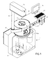
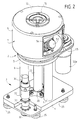
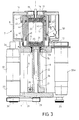
- the drawing shows a gyratory shear press 1 which has a chassis 2, the lower part 3 of which comprises a lower plate 4 and a upper plate 5 connected by three columns 6 and protected by a cover 8 and whose upper part 7 is in the form of a hollow rigid casing having a cylindrical peripheral wall 9 of revolution about a vertical axis Y, a upper wall 10 comprising an opening 11 concentric with the axis Y and a lower wall 12 fixed on the upper plate 5 and having a passage 13 of axis Y.
- the upper part 7 further comprises a sleeve 14 of axis Y which extends under the upper wall 10 opposite the passage 13.
- the rigidity of the casing 7 is constant over 360 °.
- the opening 11 is capable of being closed by a cover 15 which serves as support for the upper face of a patch 16 disposed at the end upper of a cylindrical mold 17 of axis X mounted sliding in a counter-mold cylindrical 18.
- a pellet lower 19 which can slide in the mold 19.
- the space of the mold 18 delimited by the upper tablet 16 and the lower tablet 19 is filled with a sample 20 of a compacting material, subjected on the one hand to a compressive force F exerted on the lower pad 19 in the vertical direction Y, and at a gyratory movement of the X axis around the Y axis.
- the compressive force F is exerted by the head 21 of a sheath 22 of axis Y which crosses an opening 23 of axis Y formed in the upper plate 5, with the interposition of a pad 24.
- a plate 25 of a material with low coefficient of friction is interposed between the head 21 and the underside of the lower pad 19.
- the sleeve 22 is driven in vertical translation along the direction of the Y axis by an endless screw 26 mounted on the lower plate 4 and disposed inside the sheath 22, the latter having in its lower part an internal thread 27 cooperating with the external thread of the worm.
- the sheath 22 is further guided during its vertical translation by rollers 28 which roll on the outer wall of the columns 6.
- the worm 26 is rotated by means of pulleys 29, 30 and a belt 31, by a constant torque servomotor 32 causing a reducer 33 on which the pulley 30 is mounted.
- the servomotor 32 is equipped with an angle encoder 34, the measurement of which is representative of the height of the sample 20 contained in the mold 17, between the lower pad 19 and the upper pad 16.
- the actuator assembly 32 and reducer 33 is arranged above the lower plate 4, while the pulleys 29, 30 and the belt 31 are arranged under the lower plate 4, the latter comprising a plurality of feet 35 adjustable in height.
- the device for turning the mold 17 comprises a sleeve external cylindrical 40 of axis Y rotatably mounted inside the casing 7 by means of a first bearing 41 carried by the sleeve 14 and a second bearing 42 mounted at the periphery of the passage 13 of the lower wall 12, and of a cylindrical sleeve internal 43 which is arranged inside the external sleeve 41 and mounted on this last so that it can oscillate around a horizontal axis Z located substantially in the plane of the underside of the upper pad 16, as well as shown in Figure 5.
- Two bearings 44 and 45 are interposed between the cylindrical sleeve internal 43 and the counter mold 18, in order to allow the rotation of these two parts relative to each other, while preventing their relative displacement in the direction of the axis X of the mold 17.
- a device 50 for adjusting the angle ⁇ between the axis X of the mold 17 and the vertical axis Y is provided in the median vertical plane perpendicular to the axis Z.
- This device 50 is carried by the external sleeve 40 and cooperates with a system screw / nut 51 secured to the internal sleeve. It includes a vernier 52 and a sensor effort whose power supply and data transmission are ensured by a rotating manifold 53.
- the wall device 9 of casing 7 is provided with an access door 54.
- the outer peripheral sleeve 40 is rotated by a electric motor 55a driving a toothed belt 55.
- the casing 7 is further equipped with an inductive sensor 56 used for counting the number of turns of the external cylindrical sleeve 40.
- the vernier 52 allows a setting of the angle ⁇ at 0 °, which allows make test pieces with faces parallel and perpendicular to the X axis, to make the controls of the device, and a setting of the same angle ⁇ from 30 'to 2 ° in steps of one minute in a very short time, and without means of control.
- a cabinet electric 57 which provides electric power to the drive motors 32 and 55a and various measuring instruments.
- a shelf 60 which includes the buttons 61 for starting the machine and supporting a microcomputer 62 driving the machine.
- the microcomputer 62 is connected to a keyboard 63, which allows the introduction of the characteristics of the materials to be checked, and a screen 64 for displaying the results of each sample and possibly others accessories, such as mouse, storage device, data, etc ....
- the microcomputer 62 is connected to the angle encoder 34 which provides the measurement of the height of the sample, to the inductive detector 56 and to the force sensor placed inside the device for adjusting the angle ⁇ , in order to allow data storage at the during the gyration of the mold 17 and their possible computer processing.
- bracket 70 which supports an electric winch 71 above the cover 15 for handling the mold 17.
- a sample 20 of material is placed in the mold 17 between the two pads 16 and 19.
- the mold 17 filled with material is placed in the counter mold 18 by the upper opening 11, the head 21 of the sheath 22 then being in the low position, that is to say slightly above the upper plate 5.
- the cover 15 is then fixed in the opening 11 by screwing.
- the half angle ⁇ at the top of the cone of gyration is displayed by means of the vernier 52.
- the servo motor 32 with constant torque is started, which results in an effort vertical increasing on the lower pad 19 which puts the sample 20 in a state of initial compression.
- the motor 55a When the compression force reaches the value F, the motor 55a reaches its nominal test speed, and therefore generates the rotation of the X axis of the mold around the Y axis, the X axis describing a conical surface whose vertex 0 is located in the middle of the underside of the upper patch 16.
- This gyration causes kneading by shearing of the sample 20.
- the upper pad 16 and the lower pad 19 remain parallel between them and perpendicular to the vertical axis Y.
- the resulting axial force F applied to the ends of the sample 20 and the angle ⁇ are kept constant within standard tolerances.
Landscapes
- Life Sciences & Earth Sciences (AREA)
- Chemical & Material Sciences (AREA)
- Health & Medical Sciences (AREA)
- General Physics & Mathematics (AREA)
- Pathology (AREA)
- Immunology (AREA)
- Physics & Mathematics (AREA)
- Analytical Chemistry (AREA)
- Biochemistry (AREA)
- General Health & Medical Sciences (AREA)
- Medicinal Chemistry (AREA)
- Food Science & Technology (AREA)
- Engineering & Computer Science (AREA)
- Investigating Strength Of Materials By Application Of Mechanical Stress (AREA)
- Press Drives And Press Lines (AREA)
- Presses And Accessory Devices Thereof (AREA)
- Sampling And Sample Adjustment (AREA)
- Structures Of Non-Positive Displacement Pumps (AREA)
- Crushing And Grinding (AREA)
- Disintegrating Or Milling (AREA)
- Forging (AREA)
Abstract
Description
Claims (10)
- Presse à cisaillement giratoire pour compacter des échantillons (20) de matériaux de compactage, comportantcaractérisée par le fait que :un châssis (2),un moule cylindrique (17) d'axe X destiné à recevoir un échantillon (20) interposé entre une pastille supérieure (16) et une pastille inférieure (19) maintenues parallèles entre elles ;des moyens de compression de l'échantillon portés par ledit châssis et destinés à appliquer un effort constant F sur l'une desdites pastilles selon un axe Y perpendiculaire auxdites pastilles ;des moyens pour incliner l'axe X du moule par rapport à l'axe Y ;des moyens de giration destinés à imprimer un mouvement giratoire de l'axe X autour de l'axe Y ;des moyens de commande des moyens de compression et des moyens de giration ; etdes moyens de mesure des hauteurs de l'échantillon entre les pastilles et des efforts de cisaillement de l'échantillon en fonction du nombre de girations de l'axe X ;a) le châssis (2) comporte dans sa partie supérieure un carter (7) dont la rigidité est constante sur 360° et qui présente, dans sa paroi supérieure (10), une ouverture (11) obturable par un couvercle (15) destiné à servir d'appui pour la pastille supérieure (16), et, dans sa paroi inférieure (12), un orifice pour le passage d'un élément mobile (22) des moyens de compression, qui est en appui sur la pastille inférieure (19) ;b) les moyens de giration comportent un manchon cylindrique externe (40) d'axe Y monté rotatif dans le carter (7) par l'intermédiaire de paliers (41, 42), un manchon cylindrique interne (43) d'axe X monté rotatif autour d'un contre-moule (18) d'axe X destiné à recevoir le moule (17), par l'intermédiaire de paliers (44, 45), et des moyens d'entraínement en rotation (55a) du manchon cylindrique externe (40) portés par le carter (7), le manchon cylindrique interne (43) étant disposé à l'intérieur du manchon cylindrique externe (40) et étant monté oscillant sur ce dernier de manière à pouvoir pivoter autour d'un axe Z perpendiculaire aux axes X et Y et situé sensiblement dans le plan de la pastille supérieure (19) ;c) les moyens pour incliner l'axe X du moule (17) par rapport à l'axe Y comportent un système de réglage d'angle (50) interposé entre le manchon cylindrique externe (40) et le manchon cylindrique interne (43) et situé dans le plan médian perpendiculaire à l'axe Z.
- Presse selon la revendication 1, caractérisée par le fait que la partie inférieure (3) du châssis (2) comporte une platine inférieure (4), une platine supérieure (5) sur laquelle est fixé le carter (7), et une pluralité de colonnes (6) parallèles à l'axe Y et reliant la platine inférieure (4) à la platine supérieure (5), la platine inférieure (4) supportant les moyens de compression.
- Presse selon la revendication 2, caractérisée par le fait que les moyens de compression comportent une vis sans fin (26) entraínée par des deuxièmes moyens d'entraínement (32) et un fourreau (22) entraíné en translation selon l'axe Y par la vis sans fin (26) et dont la tête (21) est en appui sur la pastille inférieure (19), ledit fourreau (22) étant guidé selon l'axe Y par des galets (28) coopérant avec les colonnes (6) et traversant une ouverture (23) ménagée dans la platine supérieure (5) avec interposition d'un coussinet (24).
- Presse selon la revendication 3, caractérisée par le fait qu'une plaque (25) à faible coefficient de friction est interposée entre la tête (21) du fourreau (22) et la pastille inférieure (19).
- Presse selon l'une quelconque des revendication 3 ou 4, caractérisée par le fait que les deuxièmes moyens d'entraínement comportent un servomoteur électrique (32) avec réducteur (33) et un codeur (34) de déplacement.
- Presse selon l'une quelconque des revendications 1 à 5, caractérisée par le fait que le système de réglage d'angle (50) est muni d'un vernier (52), et par le fait qu'une porte (54) est ménagée dans la paroi périphérique (9) du carter (7) pour accéder au vernier (52).
- Presse selon la revendication 6, caractérisée par le fait que les moyens de mesure des efforts de cisaillement comportent un capteur de cisaillement placé à l'intérieur du système de réglage d'angle (50).
- Presse selon la revendication 7, caractérisée par le fait que l'alimentation électrique du capteur de cisaillement et la transmission des données relevées par le capteur sont assurées par un collecteur tournant (53).
- Presse selon l'une quelconque des revendications 1 à 8, caractérisée par le fait que le carter (7) comporte un détecteur inductif (56) pour le comptage du nombre de tours du manchon cylindrique externe (40).
- Presse selon l'une quelconque des revendications 1 à 9, caractérisée par le fait qu'elle comporte en outre un système de manutention de moule, comprenant une potence (70) disposée au-dessus et la paroi supérieure (10) du carter (7) et un treuil (71) disposé au-dessus du couvercle (15) et supporté par la potence (70).
Applications Claiming Priority (2)
| Application Number | Priority Date | Filing Date | Title |
|---|---|---|---|
| FR9809036A FR2781283B1 (fr) | 1998-07-15 | 1998-07-15 | Presse a cisaillement giratoire |
| FR9809036 | 1998-07-15 |
Publications (2)
| Publication Number | Publication Date |
|---|---|
| EP0973022A1 true EP0973022A1 (fr) | 2000-01-19 |
| EP0973022B1 EP0973022B1 (fr) | 2003-05-02 |
Family
ID=9528636
Family Applications (1)
| Application Number | Title | Priority Date | Filing Date |
|---|---|---|---|
| EP99401651A Expired - Lifetime EP0973022B1 (fr) | 1998-07-15 | 1999-07-02 | Presse à cisaillement giratoire |
Country Status (9)
| Country | Link |
|---|---|
| US (1) | US6205864B1 (fr) |
| EP (1) | EP0973022B1 (fr) |
| AT (1) | ATE239216T1 (fr) |
| AU (1) | AU745872B2 (fr) |
| CA (1) | CA2276768C (fr) |
| DE (1) | DE69907327T2 (fr) |
| ES (1) | ES2198118T3 (fr) |
| FR (1) | FR2781283B1 (fr) |
| PT (1) | PT973022E (fr) |
Cited By (1)
| Publication number | Priority date | Publication date | Assignee | Title |
|---|---|---|---|---|
| EP2592411A3 (fr) * | 2011-11-08 | 2017-12-20 | Korea Institute of Geoscience and Mineral Resources (KIGAM) | Appareil de cisaillement annulaire en tenant compte de l'effet anti-paroi |
Families Citing this family (14)
| Publication number | Priority date | Publication date | Assignee | Title |
|---|---|---|---|---|
| SE506383C2 (sv) * | 1996-04-24 | 1997-12-08 | Anders Loennoe | Anordning för mätning av skjuvning i kärnan hos en sandwichkonstruktion |
| US6694823B2 (en) * | 2000-03-23 | 2004-02-24 | Wisconsin Alumni Research Foundation | Apparatus and method for testing material performance |
| FI114171B (fi) * | 2000-05-12 | 2004-08-31 | Antti Paakkinen | Menetelmä ja laite maamassojen ja muiden niiden kaltaisten massojen tiivistysominaisuuksien mittaamiseksi |
| FI119035B (fi) * | 2002-03-22 | 2008-06-30 | Antti Paakkinen | Menetelmä ja laitteisto kiertotiivistimen joustojen määrittämiseksi |
| US6925889B2 (en) * | 2002-10-18 | 2005-08-09 | Pine Instrument Company | Devices and methods for applying known resistance loads and measuring internal angles of gyration in gyratory compactors |
| US7121149B2 (en) * | 2003-01-10 | 2006-10-17 | Troxler Electronic Laboratories, Inc. | Gyratory compactor apparatus and associated devices and methods |
| US8438914B2 (en) * | 2010-11-13 | 2013-05-14 | Gregory P. Martiska | Apparatus for measuring the unconfined yield strength and time unconfined yield strength of bulk granular material |
| CN102889368B (zh) * | 2012-09-24 | 2015-03-11 | 中北大学 | 一种可传递拉压力的扭转传动装置 |
| TWI598150B (zh) * | 2016-09-30 | 2017-09-11 | 財團法人工業技術研究院 | 硏磨機及微旋迴轉裝置 |
| CN106769312A (zh) * | 2016-12-26 | 2017-05-31 | 立方通达实业(天津)有限公司 | 一种土样压实仪 |
| CN108088720B (zh) * | 2018-01-16 | 2024-06-25 | 董彤 | 一种倾斜砂土空心圆柱试样制备装置 |
| CN108613884A (zh) * | 2018-04-11 | 2018-10-02 | 浙江大学 | 一种可考虑常刚度常体积常应力的环剪仪 |
| AU2021103159A4 (en) * | 2020-09-22 | 2021-07-22 | Foss Analytical A/S | Preparing a pellet for laser induced breakdown spectroscopy |
| CN114839357B (zh) * | 2022-03-25 | 2023-05-16 | 河海大学 | 一种多孔沥青混合料冻胀应力与冻胀应变测试装置及方法 |
Citations (4)
| Publication number | Priority date | Publication date | Assignee | Title |
|---|---|---|---|---|
| GB911155A (en) * | 1960-04-08 | 1962-11-21 | John Leonidas Mcrae | Compacting machine |
| US5275056A (en) * | 1992-10-20 | 1994-01-04 | Rainhart Co. | Gyratory shear material compacting device |
| US5323655A (en) * | 1993-04-23 | 1994-06-28 | Troxler Electronic Laboratories, Inc. | Method and apparatus for compacting material samples |
| WO1998021558A2 (fr) * | 1996-10-28 | 1998-05-22 | Brovold Thomas E | Dispositif de compactage giratoire destine a creer des forces de compression et de cisaillement dans un materiau echantillon |
Family Cites Families (4)
| Publication number | Priority date | Publication date | Assignee | Title |
|---|---|---|---|---|
| US5456118A (en) * | 1994-02-18 | 1995-10-10 | Pine Instrument Company | Gyratory compactor |
| US5606133A (en) * | 1995-10-06 | 1997-02-25 | Pine Instrument Company | Gyratory compactor with mold specimen extruder |
| US5824913A (en) * | 1997-01-10 | 1998-10-20 | Pine Instrument Company | Portable gyratory compactor and extruder with a single pivot and two gyration actuators |
| US5939642A (en) * | 1998-03-25 | 1999-08-17 | Troxler Electronic Laboratories, Inc. | Gyratory compactor |
-
1998
- 1998-07-15 FR FR9809036A patent/FR2781283B1/fr not_active Expired - Fee Related
-
1999
- 1999-06-30 AU AU36900/99A patent/AU745872B2/en not_active Ceased
- 1999-07-02 CA CA002276768A patent/CA2276768C/fr not_active Expired - Fee Related
- 1999-07-02 EP EP99401651A patent/EP0973022B1/fr not_active Expired - Lifetime
- 1999-07-02 PT PT99401651T patent/PT973022E/pt unknown
- 1999-07-02 ES ES99401651T patent/ES2198118T3/es not_active Expired - Lifetime
- 1999-07-02 AT AT99401651T patent/ATE239216T1/de not_active IP Right Cessation
- 1999-07-02 DE DE69907327T patent/DE69907327T2/de not_active Expired - Fee Related
- 1999-07-11 US US09/350,263 patent/US6205864B1/en not_active Expired - Fee Related
Patent Citations (4)
| Publication number | Priority date | Publication date | Assignee | Title |
|---|---|---|---|---|
| GB911155A (en) * | 1960-04-08 | 1962-11-21 | John Leonidas Mcrae | Compacting machine |
| US5275056A (en) * | 1992-10-20 | 1994-01-04 | Rainhart Co. | Gyratory shear material compacting device |
| US5323655A (en) * | 1993-04-23 | 1994-06-28 | Troxler Electronic Laboratories, Inc. | Method and apparatus for compacting material samples |
| WO1998021558A2 (fr) * | 1996-10-28 | 1998-05-22 | Brovold Thomas E | Dispositif de compactage giratoire destine a creer des forces de compression et de cisaillement dans un materiau echantillon |
Cited By (1)
| Publication number | Priority date | Publication date | Assignee | Title |
|---|---|---|---|---|
| EP2592411A3 (fr) * | 2011-11-08 | 2017-12-20 | Korea Institute of Geoscience and Mineral Resources (KIGAM) | Appareil de cisaillement annulaire en tenant compte de l'effet anti-paroi |
Also Published As
| Publication number | Publication date |
|---|---|
| ATE239216T1 (de) | 2003-05-15 |
| DE69907327T2 (de) | 2004-03-25 |
| DE69907327D1 (de) | 2003-06-05 |
| CA2276768A1 (fr) | 2000-01-15 |
| EP0973022B1 (fr) | 2003-05-02 |
| FR2781283A1 (fr) | 2000-01-21 |
| PT973022E (pt) | 2003-09-30 |
| US6205864B1 (en) | 2001-03-27 |
| FR2781283B1 (fr) | 2000-10-06 |
| ES2198118T3 (es) | 2004-01-16 |
| CA2276768C (fr) | 2006-05-16 |
| AU3690099A (en) | 2000-02-10 |
| AU745872B2 (en) | 2002-04-11 |
Similar Documents
| Publication | Publication Date | Title |
|---|---|---|
| EP0973022B1 (fr) | Presse à cisaillement giratoire | |
| JP2721273B2 (ja) | 材料サンプルの成形法および成形装置 | |
| CA3075441C (fr) | Deconditionneur a nettoyage ameliore | |
| EP0365447B1 (fr) | Procédé et appareil pour la compression et le contrôle de la compression de matières pulvérulentes et presse en faisant application | |
| FR2501545A1 (fr) | Appareil portatif a cintrer les tuyaux a commande electromecanique | |
| EP0386840A1 (fr) | Micromanipulateur | |
| WO1997025757A1 (fr) | Outil portable pour le sertissage de broches de connexion sur des conducteurs electriques | |
| FR3012979A1 (fr) | Broyeur de produits enfermes dans des sacs comprenant au moins deux pales pivotantes | |
| WO2000049130A1 (fr) | Appareil de lecture automatique pour une boite de petri munie d'un couvercle | |
| EP0193461B1 (fr) | Distributeur calibreur d'éléments cylindriques | |
| FR2789694A1 (fr) | Perfectionnement pour un appareil de lecture automatique d'un antibiogramme | |
| EP0759279B1 (fr) | Grillade double-face automatisee | |
| CH464547A (fr) | Appareil de mesure de l'épaisseur d'un tube sur toute la longueur de celui-ci | |
| FR2842722A1 (fr) | Mammographie a compression simplifiee | |
| FR2593318A1 (fr) | Organe de memoire a disque magnetique | |
| EP0229736A1 (fr) | Dispositif pour recouvrir un corps cylindrique d'une bande d'un matériau de protection | |
| FR2872447A1 (fr) | Dispositif de compactage de poudre pour la fabrication de pastilles | |
| WO1999056946A1 (fr) | Presse de scellage pour documents | |
| FR2680887A1 (fr) | Dispositif de regulation de vitesse destine notamment aux malaxeurs, et nouveau malaxeur destine notamment a la fabrication de sable de fonderie. | |
| FR2683041A1 (fr) | Dispositif de mesure de la durete de grains vegetaux ou de graines vegetales. | |
| EP0761358B1 (fr) | Outil de taraudage sur presse | |
| FR2651155A1 (fr) | Dispositif broyeur de produits pulverulents. | |
| FR2605921A1 (fr) | Tourniquet de presentation d'objets | |
| EP0007837A1 (fr) | Dispositif pour mesurer la compacité de cigarettes ou articles analogues | |
| FR2557823A1 (fr) | Machine-outil pour la finition ou le tronconnage de produits longs en tube ou en barre |
Legal Events
| Date | Code | Title | Description |
|---|---|---|---|
| PUAI | Public reference made under article 153(3) epc to a published international application that has entered the european phase |
Free format text: ORIGINAL CODE: 0009012 |
|
| AK | Designated contracting states |
Kind code of ref document: A1 Designated state(s): AT BE CH CY DE DK ES FI FR GB GR IE IT LI LU MC NL PT SE |
|
| AX | Request for extension of the european patent |
Free format text: AL;LT;LV;MK;RO;SI |
|
| 17P | Request for examination filed |
Effective date: 20000627 |
|
| AKX | Designation fees paid |
Free format text: AT BE CH CY DE DK ES FI FR GB GR IE IT LI LU MC NL PT SE |
|
| AXX | Extension fees paid |
Free format text: RO PAYMENT 20000627 |
|
| GRAH | Despatch of communication of intention to grant a patent |
Free format text: ORIGINAL CODE: EPIDOS IGRA |
|
| GRAH | Despatch of communication of intention to grant a patent |
Free format text: ORIGINAL CODE: EPIDOS IGRA |
|
| GRAA | (expected) grant |
Free format text: ORIGINAL CODE: 0009210 |
|
| AK | Designated contracting states |
Designated state(s): AT BE CH CY DE DK ES FI FR GB GR IE IT LI LU MC NL PT SE |
|
| AX | Request for extension of the european patent |
Extension state: RO |
|
| PG25 | Lapsed in a contracting state [announced via postgrant information from national office to epo] |
Ref country code: NL Free format text: LAPSE BECAUSE OF FAILURE TO SUBMIT A TRANSLATION OF THE DESCRIPTION OR TO PAY THE FEE WITHIN THE PRESCRIBED TIME-LIMIT Effective date: 20030502 Ref country code: IE Free format text: LAPSE BECAUSE OF NON-PAYMENT OF DUE FEES Effective date: 20030502 Ref country code: FI Free format text: LAPSE BECAUSE OF FAILURE TO SUBMIT A TRANSLATION OF THE DESCRIPTION OR TO PAY THE FEE WITHIN THE PRESCRIBED TIME-LIMIT Effective date: 20030502 |
|
| REG | Reference to a national code |
Ref country code: GB Ref legal event code: FG4D Free format text: NOT ENGLISH |
|
| REG | Reference to a national code |
Ref country code: CH Ref legal event code: EP |
|
| REF | Corresponds to: |
Ref document number: 69907327 Country of ref document: DE Date of ref document: 20030605 Kind code of ref document: P |
|
| REG | Reference to a national code |
Ref country code: IE Ref legal event code: FG4D Free format text: FRENCH |
|
| REG | Reference to a national code |
Ref country code: CH Ref legal event code: NV Representative=s name: BOVARD AG PATENTANWAELTE |
|
| PG25 | Lapsed in a contracting state [announced via postgrant information from national office to epo] |
Ref country code: CY Free format text: LAPSE BECAUSE OF FAILURE TO SUBMIT A TRANSLATION OF THE DESCRIPTION OR TO PAY THE FEE WITHIN THE PRESCRIBED TIME-LIMIT Effective date: 20030702 |
|
| PG25 | Lapsed in a contracting state [announced via postgrant information from national office to epo] |
Ref country code: MC Free format text: LAPSE BECAUSE OF NON-PAYMENT OF DUE FEES Effective date: 20030731 |
|
| PG25 | Lapsed in a contracting state [announced via postgrant information from national office to epo] |
Ref country code: SE Free format text: LAPSE BECAUSE OF FAILURE TO SUBMIT A TRANSLATION OF THE DESCRIPTION OR TO PAY THE FEE WITHIN THE PRESCRIBED TIME-LIMIT Effective date: 20030802 Ref country code: GR Free format text: LAPSE BECAUSE OF FAILURE TO SUBMIT A TRANSLATION OF THE DESCRIPTION OR TO PAY THE FEE WITHIN THE PRESCRIBED TIME-LIMIT Effective date: 20030802 Ref country code: DK Free format text: LAPSE BECAUSE OF FAILURE TO SUBMIT A TRANSLATION OF THE DESCRIPTION OR TO PAY THE FEE WITHIN THE PRESCRIBED TIME-LIMIT Effective date: 20030802 |
|
| REG | Reference to a national code |
Ref country code: FR Ref legal event code: CL |
|
| REG | Reference to a national code |
Ref country code: PT Ref legal event code: SC4A Free format text: AVAILABILITY OF NATIONAL TRANSLATION Effective date: 20030717 |
|
| NLV1 | Nl: lapsed or annulled due to failure to fulfill the requirements of art. 29p and 29m of the patents act | ||
| GBT | Gb: translation of ep patent filed (gb section 77(6)(a)/1977) | ||
| REG | Reference to a national code |
Ref country code: IE Ref legal event code: FD4D Ref document number: 0973022E Country of ref document: IE |
|
| REG | Reference to a national code |
Ref country code: ES Ref legal event code: FG2A Ref document number: 2198118 Country of ref document: ES Kind code of ref document: T3 |
|
| PLBE | No opposition filed within time limit |
Free format text: ORIGINAL CODE: 0009261 |
|
| STAA | Information on the status of an ep patent application or granted ep patent |
Free format text: STATUS: NO OPPOSITION FILED WITHIN TIME LIMIT |
|
| 26N | No opposition filed |
Effective date: 20040203 |
|
| PGFP | Annual fee paid to national office [announced via postgrant information from national office to epo] |
Ref country code: LU Payment date: 20050617 Year of fee payment: 7 Ref country code: AT Payment date: 20050617 Year of fee payment: 7 |
|
| PGFP | Annual fee paid to national office [announced via postgrant information from national office to epo] |
Ref country code: PT Payment date: 20050630 Year of fee payment: 7 |
|
| PGFP | Annual fee paid to national office [announced via postgrant information from national office to epo] |
Ref country code: DE Payment date: 20050707 Year of fee payment: 7 |
|
| PGFP | Annual fee paid to national office [announced via postgrant information from national office to epo] |
Ref country code: CH Payment date: 20050713 Year of fee payment: 7 |
|
| PGFP | Annual fee paid to national office [announced via postgrant information from national office to epo] |
Ref country code: BE Payment date: 20050728 Year of fee payment: 7 |
|
| PG25 | Lapsed in a contracting state [announced via postgrant information from national office to epo] |
Ref country code: AT Free format text: LAPSE BECAUSE OF NON-PAYMENT OF DUE FEES Effective date: 20060702 |
|
| PG25 | Lapsed in a contracting state [announced via postgrant information from national office to epo] |
Ref country code: LI Free format text: LAPSE BECAUSE OF NON-PAYMENT OF DUE FEES Effective date: 20060731 Ref country code: CH Free format text: LAPSE BECAUSE OF NON-PAYMENT OF DUE FEES Effective date: 20060731 Ref country code: BE Free format text: LAPSE BECAUSE OF NON-PAYMENT OF DUE FEES Effective date: 20060731 |
|
| PGFP | Annual fee paid to national office [announced via postgrant information from national office to epo] |
Ref country code: IT Payment date: 20060731 Year of fee payment: 8 |
|
| PG25 | Lapsed in a contracting state [announced via postgrant information from national office to epo] |
Ref country code: PT Free format text: LAPSE BECAUSE OF NON-PAYMENT OF DUE FEES Effective date: 20070102 |
|
| REG | Reference to a national code |
Ref country code: PT Ref legal event code: MM4A Free format text: LAPSE DUE TO NON-PAYMENT OF FEES Effective date: 20070102 |
|
| PG25 | Lapsed in a contracting state [announced via postgrant information from national office to epo] |
Ref country code: DE Free format text: LAPSE BECAUSE OF NON-PAYMENT OF DUE FEES Effective date: 20070201 |
|
| REG | Reference to a national code |
Ref country code: CH Ref legal event code: PL |
|
| BERE | Be: lapsed |
Owner name: LABORATOIRE CENTRAL DES *PONTS ET CHAUSSEES Effective date: 20060731 |
|
| PG25 | Lapsed in a contracting state [announced via postgrant information from national office to epo] |
Ref country code: LU Free format text: LAPSE BECAUSE OF NON-PAYMENT OF DUE FEES Effective date: 20060702 |
|
| PG25 | Lapsed in a contracting state [announced via postgrant information from national office to epo] |
Ref country code: IT Free format text: LAPSE BECAUSE OF NON-PAYMENT OF DUE FEES Effective date: 20070702 |
|
| PGFP | Annual fee paid to national office [announced via postgrant information from national office to epo] |
Ref country code: GB Payment date: 20110627 Year of fee payment: 13 |
|
| PGFP | Annual fee paid to national office [announced via postgrant information from national office to epo] |
Ref country code: ES Payment date: 20110726 Year of fee payment: 13 |
|
| REG | Reference to a national code |
Ref country code: FR Ref legal event code: TP Owner name: INSTITUT FRANCAIS DES SCIENCES ET TECHNOLOGIES, FR Effective date: 20120515 |
|
| GBPC | Gb: european patent ceased through non-payment of renewal fee |
Effective date: 20120702 |
|
| PG25 | Lapsed in a contracting state [announced via postgrant information from national office to epo] |
Ref country code: GB Free format text: LAPSE BECAUSE OF NON-PAYMENT OF DUE FEES Effective date: 20120702 |
|
| REG | Reference to a national code |
Ref country code: ES Ref legal event code: FD2A Effective date: 20131022 |
|
| PG25 | Lapsed in a contracting state [announced via postgrant information from national office to epo] |
Ref country code: ES Free format text: LAPSE BECAUSE OF NON-PAYMENT OF DUE FEES Effective date: 20120703 |
|
| REG | Reference to a national code |
Ref country code: FR Ref legal event code: PLFP Year of fee payment: 18 |
|
| REG | Reference to a national code |
Ref country code: FR Ref legal event code: PLFP Year of fee payment: 19 |
|
| REG | Reference to a national code |
Ref country code: FR Ref legal event code: PLFP Year of fee payment: 20 |
|
| PGFP | Annual fee paid to national office [announced via postgrant information from national office to epo] |
Ref country code: FR Payment date: 20180720 Year of fee payment: 20 |