EP0971444B1 - Modular plug having a circuit board - Google Patents
Modular plug having a circuit board Download PDFInfo
- Publication number
- EP0971444B1 EP0971444B1 EP99305018A EP99305018A EP0971444B1 EP 0971444 B1 EP0971444 B1 EP 0971444B1 EP 99305018 A EP99305018 A EP 99305018A EP 99305018 A EP99305018 A EP 99305018A EP 0971444 B1 EP0971444 B1 EP 0971444B1
- Authority
- EP
- European Patent Office
- Prior art keywords
- circuit board
- modular plug
- contacts
- electrical connector
- terminals
- Prior art date
- Legal status (The legal status is an assumption and is not a legal conclusion. Google has not performed a legal analysis and makes no representation as to the accuracy of the status listed.)
- Expired - Lifetime
Links
Images


Classifications
-
- H—ELECTRICITY
- H01—ELECTRIC ELEMENTS
- H01R—ELECTRICALLY-CONDUCTIVE CONNECTIONS; STRUCTURAL ASSOCIATIONS OF A PLURALITY OF MUTUALLY-INSULATED ELECTRICAL CONNECTING ELEMENTS; COUPLING DEVICES; CURRENT COLLECTORS
- H01R24/00—Two-part coupling devices, or either of their cooperating parts, characterised by their overall structure
- H01R24/60—Contacts spaced along planar side wall transverse to longitudinal axis of engagement
- H01R24/62—Sliding engagements with one side only, e.g. modular jack coupling devices
- H01R24/64—Sliding engagements with one side only, e.g. modular jack coupling devices for high frequency, e.g. RJ 45
-
- H—ELECTRICITY
- H01—ELECTRIC ELEMENTS
- H01R—ELECTRICALLY-CONDUCTIVE CONNECTIONS; STRUCTURAL ASSOCIATIONS OF A PLURALITY OF MUTUALLY-INSULATED ELECTRICAL CONNECTING ELEMENTS; COUPLING DEVICES; CURRENT COLLECTORS
- H01R4/00—Electrically-conductive connections between two or more conductive members in direct contact, i.e. touching one another; Means for effecting or maintaining such contact; Electrically-conductive connections having two or more spaced connecting locations for conductors and using contact members penetrating insulation
- H01R4/24—Connections using contact members penetrating or cutting insulation or cable strands
- H01R4/2416—Connections using contact members penetrating or cutting insulation or cable strands the contact members having insulation-cutting edges, e.g. of tuning fork type
- H01R4/242—Connections using contact members penetrating or cutting insulation or cable strands the contact members having insulation-cutting edges, e.g. of tuning fork type the contact members being plates having a single slot
- H01R4/2425—Flat plates, e.g. multi-layered flat plates
- H01R4/2429—Flat plates, e.g. multi-layered flat plates mounted in an insulating base
- H01R4/2433—Flat plates, e.g. multi-layered flat plates mounted in an insulating base one part of the base being movable to push the cable into the slot
Landscapes
- Coupling Device And Connection With Printed Circuit (AREA)
- Details Of Connecting Devices For Male And Female Coupling (AREA)
Description
- The invention relates to a modular plug electrical connector having a circuit board that is coupled between external communications wires and terminals in the connector.
- Modular plugs and modular jacks are commonly used for interconnecting plural wires in a communications system. Signal lines in a communications system are subject to crosstalk which increases in magnitude as operating frequencies of the system are increased. Previous efforts to reduce crosstalk have focused primarily on the crosstalk which occurs in the modular jack. A new standard promulgated by the Electronic Industries Association (EIA) sets crosstalk specifications for the modular plug.
- A typical modular plug electrical connector according to the preamble of
claim 1 is disclosed inDE 29804543 U1 . - A further connector. is disclosed in patent
EP-A-0793305 . The connector includes an insulating housing in which insulation displacement contacts engage a plurality of wires. The wires are juxtaposed relative to each other to reduce crosstalk therebetween. - A further such connector is disclosed in
EP-A-0782221 , in which connection between wire engaging contacts and terminals of the connector is provided by a circuit board. - A new concept for reducing crosstalk in a modular plug involves adding a compensating insert to the modular plug. Details of this new concept are disclosed in
U.S. patent application serial number 08/979,805 filed November 25, 1997 - A problem presented is how to connect the traces on the circuit board to the terminals of the modular plug.
- This problem is solved by a modular plug electrical connector comprising a dielectric housing which holds a plurality of terminals that are engageable with terminals of a mating modular jack. A circuit board having an array of circuit holes is mounted in the housing. Each of the terminals has a leg that extends into a respective one of the circuit holes for electrical connection with the circuit board and for mechanical retention of the circuit board to the housing.
- The invention will now be described by way of example with reference to the accompanying drawings wherein:
-
Fig. 1 is a top front isometric view of a modular plug electrical connector according to the invention; -
Fig. 2 is an exploded isometric view of the modular plug; -
Fig. 3 is a rear isometric view of a housing used in the modular plug; -
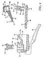
Fig. 4 is a cross-sectional view through components of the modular plug in exploded condition; -
Fig. 5 is a top plan view of a circuit board used in the modular plug; -
Fig. 6 is a partially exploded isometric view showing a housing, terminals, stuffer cap and circuit board used in the modular plug; -
Fig. 7 is a rear view of the stuffer cap and circuit board used in the modular plug; -
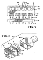
Fig. 8 is an isometric view of the modular plug showing the stuffer cap in an open position and a wire disposed in the stuffer cap prior to being terminated: -
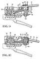
Fig. 9 is a cross-sectional view through the modular plug showing the stuffer cap in the open position prior to terminating a wire; and -
Fig. 10 is a cross-sectional view through the modular plug showing the stuffer cap in a closed position and the wire having been terminated. - There is shown in
Figs. 1 and2 a modular plugelectrical connector 10 which is matable with a modular jack (not shown) for interconnecting a plurality of wires 12 (only one of which is shown) in a communications system. The wires in a communications system are typically twisted together in pairs which are associated as signal pairs, and the twisted pairs of wires are bundled within an insulative jacket. Each of theindividual wires 12 includes a conductive core which is surrounded by a sleeve of insulation. - The
modular plug connector 10 comprises adielectric housing 20 which holds a plurality ofterminals 30 that are arranged side-by-side inrespective slots 22 at aforward end 23 of the housing. Each of theterminals 30 has acontact face 32 which is adapted for engaging a terminal in the modular jack, and aleg 34 which is adapted for insertion in a hole in acircuit board 40. The number ofterminals 30 corresponds to the number ofwires 12 in the communications cable with which the modular plug is being used. The modular plug in the illustrated embodiment is an eight position electrical connector having eightterminals 30 which can be terminated to eightwires 12 of a standard four pair communications cable. However, it should be understood that the invention can be embodied in a modular plug which is configured for terminating any number of wires. Theterminals 30 are assignedrespective numbers 1thru 8 corresponding to their positions in the housing, and thesenumbers 1thru 8 in turn designate respective electrical paths which run through the terminals. - As shown in
Figs. 3 and4 , thehousing 20 has acavity 24 which opens into the housing through arear face 25 of the housing. Thecavity 24 is open to theslots 22 in an interior of the housing. The housing has aresilient latch arm 26 of known configuration which is operable to releasably secure the modular plug connector to the mating modular jack. - The
circuit board 40 is mountable in thecavity 24 of the housing. As best seen inFig. 5 , thecircuit board 40 has a first array ofcircuit holes 41 at a front or terminal end of the board. Thecircuit holes 41 are electrically connected to a second array ofcircuit holes 44 at a rear or wire end of the board by conductive traces (not shown). The conductive traces are arranged on the board in a spatial relationship that provides desired capacitive couplings between signal pairs so as to reduce crosstalk in the modular jack connector. A number of schemes which reduce crosstalk by routing of traces on a board are known, and all such schemes are considered to be within the scope of the invention. - Each of the
circuit holes 41 in the first array is associated with one of theterminals 30 and may be assigned arespective number 1thru 8 according to the number of itsassociated terminal 30. Each of thecircuit holes 41 is preferably a plated circuit hole. Thecircuit holes 41 are arranged in twolinear rows 42, 43 that are spaced-apart and extend laterally across the circuit board. Thus, thecircuit holes 41 are longitudinally staggered as they extend laterally across the board in order to increase the density of circuit holes having a particular centerline spacing. - The
circuit holes 44 in the second array are arranged in eight pairs corresponding to the eight wires which are to be terminated by the modular plug. Each of the circuit hole pairs comprises one circuit hole inlateral row 45 and one circuit hole inlateral row 46. It should be understood that only one circuit hole of each circuit hole pair is required to be electrically connected to a circuit trace on the circuit board. The circuit hole pairs are oriented in respective longitudinal rows such asrows longitudinal rows longitudinal rows - Referring back to
Figs. 2 and4 , a plurality ofcontacts 50 are mounted on thecircuit board 40. Each of thecontacts 50 is a planar body having an upper portion including a pair ofarms 52 withtips 53 which are configured to pierce the insulation of one of thewires 12, and a lower portion including a pair oflegs 54 which are initially straight to permit insertion of the legs through one of the pairs ofcircuit holes 44. After insertion, thelegs 54 are bent as shown inFig. 9 to clinch thecircuit board 40 from below and thereby secure thecontact 50 to the circuit board. When thecontacts 50 are mounted on the board, the planar contact bodies are arranged in respective parallel planes and in respective contact pairs in accordance with the footprint of thecircuit holes 44. - A noteworthy feature of each
contact 50 is that acentral axis 55 between the pair ofarms 52 is angled with respect to acentral axis 56 between the pair oflegs 54. A relative angle between theaxes contact 50 is installed in the circuit board as shown inFig. 10 , thecentral axis 56 extends perpendicular to the circuit board and thecentral axis 55 is inclined with respect to theaxis 56. - With reference to
Figs. 4 ,6 and7 , the modular plug includes astuffer cap 60. The stuffer cap includes ablock member 62 having eightwire channels 63 each of which is dimensioned to receive one of the eightwires 12. Thewire channels 63 are arranged in foursiamesed pairs 64 that have an open wall at 65 between the paired wire channels. Each of the siamesed pairs 64 is intended to receive two wires of a same twisted wire pair. Thewire channels 63 may be tapered in width as they extend axially through theblock member 62. In particular, a cross-sectional dimension of thewire channel 63 in the vicinity ofwire entrance 66 may be less than a cross-sectional dimension of the wire channel in the vicinity ofwire exit 67, for a reason to be explained. - The
stuffer cap 60 has eightslots 68 which are open from a bottom 69 of the stuffer cap into respective ones of thewire channels 63. Each of theslots 68 is dimensioned to closely receive one of thecontacts 50. - The
stuffer cap 60 includes arigid plate member 70 having a free end which formspivot members 72. Thepivot members 72 are joined by alink 73 that spans anopening 74 in theplate member 70. - With reference to
Figs. 8 and9 , a circuit board subassembly comprising thecircuit board 40, thecontacts 50 and thestuffer cap 60 is installed in thecavity 24 in thehousing 20. The stuffer cap is disposed in an initial or open position wherein thecontacts 50 are partially within theslots 68 but have not entered thewire channels 63. Theterminals 30, which are initially held in a pre-stage position in theslots 22, are driven downwardly so that thelegs 34 of the terminals enter the circuit holes 41 in the circuit board. Thus, thelegs 34 of the terminals serve to mechanically retain the circuit board in the housing and electrically engage with circuit paths on the circuit board. Thelegs 34 may be long enough to extend through the circuit board and into housing material below the circuit board to better retain the board in the housing. With the circuit board in this position, thestuffer cap 60 is trapped between arear portion 27 of the housing and thecontacts 50 which are partially within theslots 68. With the stuffer cap in the open position, pairs of thetwisted wires 12 may be inserted in the siamesed pairs 64 of wire channels and pulled forwardly until the cable jacket abuts the rear of theblock member 62, thereby minimizing any untwisted length of the wires. - With reference to
Fig. 10 , the stuffer cap is driven to a closed or final position with a suitable tool by pivoting the stuffer cap on the pivot members 72 (Fig. 9 ) in order to drive thetips 53 of thecontact arms 52 through the cores of thewires 12, thereby electrically connecting the wires through thecircuit board 40 to theterminals 30. Further, driving thecontact arms 52 into the wires causes the insulation of each wire to swell in size, and the swollen insulation in combination with the tapered cross-section of thewire channel 63 results in a wedging action that serves to lock thewires 12 in the wire channels and to provide strain relief for the wires. - Concurrent with or subsequent to driving the stuffer cap to the closed position, a
ledge 28 of the housing is sheared at connectingstrip 29 and is driven downwardly behind thelink 73 of the stuffer cap in order to provide supplemental retention of the stuffer cap to the modular plug. - It should also be noted that when the stuffer cap is in the closed position, a
central axis 75 of eachwire channel 63 is inclined with respect to thecircuit board 40 and is perpendicular to thecentral axis 55 of thecontact legs 54. Theinclined axis 75 serves to expose anend 13 of thewire 12 in a gap between the stuffercap block member 62 and therear face 25 of the housing so that thewire end 13 can be trimmed away. - Finally, a
metal shield 80 is installed over the stuffer cap and the rear portion of the housing. The metal shield protects the circuit board subassembly from contaminants and shields the signal paths from electromagnetic interference. - The invention provides a modular plug electrical connector having a circuit board which may include circuit traces that are routed to provide desired electrical couplings between selected circuits, thereby reducing electrical crosstalk in the connector. The circuit board is mechanically retained in the modular plug by terminals of the modular plug which are matable with terminals of a modular jack. The circuit board has contacts for connecting with wires of a communications system, and a stuffer cap for driving the wires into engagement with the contacts. Each of the contacts has a central axis which is inclined from perpendicular to the circuit board. The stuffer cap has wire-receiving channels which are arranged in siamesed pairs which receive twisted wire pairs, thereby minimizing any untwisted length of the wires.
Claims (10)
- A modular plug electrical connector (10) comprising a dielectric housing (20) with a plurality of terminals (30) that are engageable with terminals of a mating modular jack, and a circuit board (40) mounted in the housing, the circuit board having an array of circuit holes (41), each of the terminals having a leg (34) that extends into a respective one of the circuit holes (41) for electrical connection with the circuit board (40) characterized in that the dielectric housing (20) holds the plurality of terminals and the legs (34) extending into the circuit holes (41) mechanically retain the circuit board (40) to the housing (20).
- The modular plug electrical connector of claim 1 wherein the terminals (30) are planar bodies that are arranged in respective parallel planes, and the legs (34) of the terminals are arranged in two rows (42, 43) that extend perpendicular to the planes.
- The modular plug electrical connector of claim 1 or 2 wherein each of the legs (34) extends through the circuit board (40) and engages in a wall of the housing (20) on an opposite side of the circuit board.
- The modular plug electrical connector of claim 1, 2 or 3 wherein the circuit board (40) carries contacts (50) for terminating wires (12) of a communications system.
- The modular plug electrical connector of claim 4 wherein the contacts (50) are bodies that are arranged in respective parallel planes.
- The modular plug electrical connector of claim 4 or 5 wherein each of the contacts (50) has a central axis (55) that is inclined from a line (56) that is perpendicular to the circuit board.
- The modular plug electrical connector of claim 4, 5 or 6 wherein the contacts (50) are arranged in respective contact pairs, and a space (D1) between contacts in one contact pair is less than a space (D2) between adjacent contacts of an adjacent pair of contacts.
- The modular plug electrical connector of any of claims 4 to 7 comprising a stuffer cap (60) having wire channels (63) that are associated with the contacts (50), the stuffer cap being initially mounted on the circuit board (40) in an open position wherein the wires (12) can be installed in the wire channels, and the stuffer cap being movable to a closed position wherein the wires (12) are urged into electrical connection with the contacts (50), the wire channels being arranged in siamesed or interconnected pairs (64) that are associated with respective ones of the contact pairs.
- The modular plug electrical connector of claim 8 wherein the wire channels (63) are inclined with respect to the circuit board when the stuffer cap is in the closed position.
- The modular plug electrical connector of claim 8 or 9 wherein each of the wire channels (63) has a cross-sectional dimension perpendicular to its longitudinal axis which is non-uniform.
Applications Claiming Priority (2)
| Application Number | Priority Date | Filing Date | Title |
|---|---|---|---|
| US09/107,814 US6116943A (en) | 1998-06-30 | 1998-06-30 | Modular plug having a circuit board |
| US107814 | 1998-06-30 |
Publications (2)
| Publication Number | Publication Date |
|---|---|
| EP0971444A1 EP0971444A1 (en) | 2000-01-12 |
| EP0971444B1 true EP0971444B1 (en) | 2008-08-13 |
Family
ID=22318630
Family Applications (1)
| Application Number | Title | Priority Date | Filing Date |
|---|---|---|---|
| EP99305018A Expired - Lifetime EP0971444B1 (en) | 1998-06-30 | 1999-06-25 | Modular plug having a circuit board |
Country Status (5)
| Country | Link |
|---|---|
| US (1) | US6116943A (en) |
| EP (1) | EP0971444B1 (en) |
| CN (1) | CN2418593Y (en) |
| DE (1) | DE69939297D1 (en) |
| TW (1) | TW435874U (en) |
Families Citing this family (46)
| Publication number | Priority date | Publication date | Assignee | Title |
|---|---|---|---|---|
| FR2791816B1 (en) * | 1999-04-01 | 2001-06-15 | Infra Sa | LOW VOLTAGE MALE CONNECTOR |
| US6338643B1 (en) | 2000-09-29 | 2002-01-15 | Hubbell Incorporated | Stuffer cap mechanism for an electrical connector |
| DE10065136C2 (en) * | 2000-12-29 | 2003-01-09 | Phoenix Contact Gmbh & Co | Connection device and method for connecting a multi-core cable to a connector |
| US6312281B1 (en) * | 2001-01-08 | 2001-11-06 | Andrew Corporation | Tap connector |
| US6579116B2 (en) | 2001-03-12 | 2003-06-17 | Sentinel Holding, Inc. | High speed modular connector |
| US6439920B1 (en) * | 2001-09-18 | 2002-08-27 | Surtec Industries Inc. | Electronic connector plug for high speed transmission |
| US20030116935A1 (en) * | 2001-12-26 | 2003-06-26 | Adam Zadok | Anti-roll vehicle suspension |
| GB2398677A (en) * | 2003-02-18 | 2004-08-25 | Hsu & Overmatt Co Ltd | Electrical connector with IDC pins |
| BE1015495A3 (en) * | 2003-03-04 | 2005-05-03 | Hsu & Overmaat Co Ltd | Electrical connector for automatic assembly to provide connection for a conductor or appropriate tools such as in telephone systems or computer networks |
| US20040209511A1 (en) * | 2003-04-21 | 2004-10-21 | Liao Sheng Hsin | Electrical plug with protection cover |
| US6776660B1 (en) | 2003-04-30 | 2004-08-17 | Japan Aviation Electronics Industry, Limited | Connector |
| CN100384019C (en) * | 2003-11-25 | 2008-04-23 | 康福特仪器(杭州)有限公司 | Electric connector capable of stripping insulation layer |
| US6932641B1 (en) * | 2004-02-20 | 2005-08-23 | Sheng Hsin Liao | Plug structure |
| US7001204B1 (en) * | 2005-01-12 | 2006-02-21 | Jyh Eng Technology Co., Ltd. | Transmitting jack with prong-type conductive pieces |
| US20060246784A1 (en) * | 2005-04-29 | 2006-11-02 | Aekins Robert A | Electrically isolated shielded connector system |
| US20070254714A1 (en) * | 2006-05-01 | 2007-11-01 | Martich Mark E | Wireless access point |
| US7322860B2 (en) * | 2006-05-01 | 2008-01-29 | Ortronics, Inc. | Plug assembly including integral printed circuit board |
| TWI310999B (en) * | 2006-05-19 | 2009-06-11 | John Peng | Network jack and method for fabricating the same |
| US7530854B2 (en) * | 2006-06-15 | 2009-05-12 | Ortronics, Inc. | Low noise multiport connector |
| US7288001B1 (en) | 2006-09-20 | 2007-10-30 | Ortronics, Inc. | Electrically isolated shielded multiport connector assembly |
| US20080115356A1 (en) * | 2006-11-17 | 2008-05-22 | Peterson Karl J | Cable preform tool |
| CN101595536B (en) * | 2006-12-01 | 2013-03-06 | 西蒙公司 | Modular connector with reduced termination variability |
| US7540788B2 (en) * | 2007-01-05 | 2009-06-02 | Apple Inc. | Backward compatible connector system |
| DE102007008465B4 (en) * | 2007-02-19 | 2008-10-16 | Tyco Electronics Amp Gmbh | Electrical connector module, in particular for an RJ 45 connector |
| US8095713B2 (en) * | 2007-09-04 | 2012-01-10 | Apple Inc. | Smart cables |
| US8197286B2 (en) * | 2009-06-11 | 2012-06-12 | Commscope, Inc. Of North Carolina | Communications plugs having capacitors that inject offending crosstalk after a plug-jack mating point and related connectors and methods |
| DE102010014294A1 (en) * | 2010-04-08 | 2011-10-13 | Phoenix Contact Gmbh & Co. Kg | Contact field for connectors |
| US7967614B1 (en) | 2010-04-28 | 2011-06-28 | Tyco Electronics Corporation | Plug connector and connector assembly having a pluggable board substrate |
| US7883354B1 (en) * | 2010-08-26 | 2011-02-08 | Hong Fu Jin Precision Industry (Shenzhen) Co., Ltd. | Modular plug |
| US8690598B2 (en) * | 2010-10-21 | 2014-04-08 | Panduit Corp. | Communication plug with improved crosstalk |
| US8591248B2 (en) | 2011-01-20 | 2013-11-26 | Tyco Electronics Corporation | Electrical connector with terminal array |
| US8257117B2 (en) | 2011-01-20 | 2012-09-04 | Tyco Electronics Corporation | Electrical connector having a first group of terminals taller than that of a second group or located in a non-parallel plane |
| US8647146B2 (en) | 2011-01-20 | 2014-02-11 | Tyco Electronics Corporation | Electrical connector having crosstalk compensation insert |
| TWI493808B (en) * | 2012-11-16 | 2015-07-21 | Frank Ma | Transmission connector |
| US8764476B1 (en) | 2012-12-06 | 2014-07-01 | Frank Ma | Transmission connector |
| GB2510572A (en) * | 2013-02-07 | 2014-08-13 | 3M Innovative Properties Co | Plug with cross-talk compensation |
| WO2014158975A1 (en) | 2013-03-12 | 2014-10-02 | Tyco Electronics Corporation | Notched contact for a modular plug |
| US8992247B2 (en) * | 2013-03-15 | 2015-03-31 | Ortronics, Inc. | Multi-surface contact plug assemblies, systems and methods |
| WO2015007939A2 (en) * | 2013-07-15 | 2015-01-22 | Te Connectivity Amp España, S.L.U. | Telecommunications plug connector for high data rate uses |
| US9543729B2 (en) * | 2013-08-19 | 2017-01-10 | Sullstar Technologies, Inc | Electrical connector with removable external load bar, and method of its use |
| US9640924B2 (en) | 2014-05-22 | 2017-05-02 | Panduit Corp. | Communication plug |
| TWM536801U (en) | 2016-10-21 | 2017-02-11 | Jyh Eng Technology Co Ltd | Network plug structure |
| WO2020007952A1 (en) * | 2018-07-03 | 2020-01-09 | Aqueous Group Ag | Connecting device |
| WO2020006586A1 (en) * | 2018-07-03 | 2020-01-09 | Bertelt Peter | Connecting device |
| TWI757933B (en) * | 2020-10-27 | 2022-03-11 | 好慶科技企業股份有限公司 | Electrical plug |
| US11705681B2 (en) * | 2021-08-19 | 2023-07-18 | Panduit Corp. | Field terminable ethernet connector with integral termination cap |
Citations (1)
| Publication number | Priority date | Publication date | Assignee | Title |
|---|---|---|---|---|
| DE29804543U1 (en) * | 1998-03-13 | 1998-06-18 | Hsing Chau Ind Co | Module connector |
Family Cites Families (6)
| Publication number | Priority date | Publication date | Assignee | Title |
|---|---|---|---|---|
| US5503572A (en) * | 1994-05-17 | 1996-04-02 | Mod-Tap Corporation | Communications connectors |
| FR2723479B1 (en) * | 1994-08-08 | 1996-09-13 | Connectors Pontarlier | LOW CROSS-LINK NETWORK CONNECTION |
| US5628647A (en) * | 1995-02-22 | 1997-05-13 | Stewart Connector Systems, Inc. | High frequency modular plug and cable assembly |
| US5766027A (en) * | 1995-12-21 | 1998-06-16 | The Whitaker Corporation | Cable assembly with equalizer board |
| AU716436B2 (en) * | 1995-12-25 | 2000-02-24 | Matsushita Electric Works Ltd. | Connector |
| GB9603751D0 (en) * | 1996-02-22 | 1996-04-24 | Amp Espa Ola S A | Twisted pair cable and connector assembly |
-
1998
- 1998-06-30 US US09/107,814 patent/US6116943A/en not_active Expired - Lifetime
-
1999
- 1999-06-25 EP EP99305018A patent/EP0971444B1/en not_active Expired - Lifetime
- 1999-06-25 DE DE69939297T patent/DE69939297D1/en not_active Expired - Lifetime
- 1999-06-28 TW TW088210622U patent/TW435874U/en not_active IP Right Cessation
- 1999-06-30 CN CN99215601U patent/CN2418593Y/en not_active Expired - Lifetime
Patent Citations (1)
| Publication number | Priority date | Publication date | Assignee | Title |
|---|---|---|---|---|
| DE29804543U1 (en) * | 1998-03-13 | 1998-06-18 | Hsing Chau Ind Co | Module connector |
Also Published As
| Publication number | Publication date |
|---|---|
| US6116943A (en) | 2000-09-12 |
| CN2418593Y (en) | 2001-02-07 |
| TW435874U (en) | 2001-05-16 |
| DE69939297D1 (en) | 2008-09-25 |
| EP0971444A1 (en) | 2000-01-12 |
Similar Documents
| Publication | Publication Date | Title |
|---|---|---|
| EP0971444B1 (en) | Modular plug having a circuit board | |
| EP1188204B1 (en) | Modular electrical plug, plug-cable assemblies including the same, and load bar and terminal blade for same | |
| EP1295363B1 (en) | High speed connector | |
| US5967801A (en) | Modular plug having compensating insert | |
| US4406512A (en) | Triple row coax cable connector | |
| US5376018A (en) | High-density cable connector | |
| US6524128B2 (en) | Modular plug wire aligner | |
| US5380223A (en) | High density electrical connector | |
| US5971812A (en) | Modular plug having a circuit board | |
| US6582255B2 (en) | High-density plug connector for twisted pair cable | |
| EP2048747A2 (en) | Modular electrical connector with enhanced plug interface | |
| US6663419B2 (en) | Reduced crosstalk modular plug and patch cord incorporating the same | |
| US4762507A (en) | Electrical contact retention system, and tool for removal and method therefor | |
| US6332802B2 (en) | Modular plug and harnessed plug | |
| EP0847111B1 (en) | Modular plug with automatically staggered wires | |
| US6059601A (en) | Single-sided press-pinching connector and a method of making same | |
| US5593314A (en) | Staggered terminal array for mod plug | |
| US5997348A (en) | Electrical assembly with grounding strip connecting cable screens | |
| US6234843B1 (en) | Low profile filter connector with ferrite | |
| US4674822A (en) | Multi-conductor shielded cable | |
| US4864719A (en) | Tool for removing electrical contacts | |
| EP0891018B1 (en) | Connector | |
| US4874330A (en) | Capacity modular plug | |
| US4864721A (en) | Method for removing an electrical contact from a housing | |
| US20040115983A1 (en) | Electrical plug with reduced cross talk |
Legal Events
| Date | Code | Title | Description |
|---|---|---|---|
| PUAI | Public reference made under article 153(3) epc to a published international application that has entered the european phase |
Free format text: ORIGINAL CODE: 0009012 |
|
| AK | Designated contracting states |
Kind code of ref document: A1 Designated state(s): DE FR GB |
|
| AX | Request for extension of the european patent |
Free format text: AL;LT;LV;MK;RO;SI |
|
| 17P | Request for examination filed |
Effective date: 20000623 |
|
| AKX | Designation fees paid |
Free format text: DE FR GB |
|
| GRAP | Despatch of communication of intention to grant a patent |
Free format text: ORIGINAL CODE: EPIDOSNIGR1 |
|
| GRAS | Grant fee paid |
Free format text: ORIGINAL CODE: EPIDOSNIGR3 |
|
| GRAA | (expected) grant |
Free format text: ORIGINAL CODE: 0009210 |
|
| AK | Designated contracting states |
Kind code of ref document: B1 Designated state(s): DE FR GB |
|
| REG | Reference to a national code |
Ref country code: GB Ref legal event code: FG4D |
|
| REF | Corresponds to: |
Ref document number: 69939297 Country of ref document: DE Date of ref document: 20080925 Kind code of ref document: P |
|
| PLBE | No opposition filed within time limit |
Free format text: ORIGINAL CODE: 0009261 |
|
| STAA | Information on the status of an ep patent application or granted ep patent |
Free format text: STATUS: NO OPPOSITION FILED WITHIN TIME LIMIT |
|
| 26N | No opposition filed |
Effective date: 20090514 |
|
| REG | Reference to a national code |
Ref country code: FR Ref legal event code: PLFP Year of fee payment: 18 |
|
| PGFP | Annual fee paid to national office [announced via postgrant information from national office to epo] |
Ref country code: GB Payment date: 20160627 Year of fee payment: 18 |
|
| PGFP | Annual fee paid to national office [announced via postgrant information from national office to epo] |
Ref country code: FR Payment date: 20160628 Year of fee payment: 18 |
|
| PGFP | Annual fee paid to national office [announced via postgrant information from national office to epo] |
Ref country code: DE Payment date: 20160628 Year of fee payment: 18 |
|
| REG | Reference to a national code |
Ref country code: DE Ref legal event code: R119 Ref document number: 69939297 Country of ref document: DE |
|
| GBPC | Gb: european patent ceased through non-payment of renewal fee |
Effective date: 20170625 |
|
| REG | Reference to a national code |
Ref country code: FR Ref legal event code: ST Effective date: 20180228 |
|
| PG25 | Lapsed in a contracting state [announced via postgrant information from national office to epo] |
Ref country code: DE Free format text: LAPSE BECAUSE OF NON-PAYMENT OF DUE FEES Effective date: 20180103 Ref country code: GB Free format text: LAPSE BECAUSE OF NON-PAYMENT OF DUE FEES Effective date: 20170625 |
|
| PG25 | Lapsed in a contracting state [announced via postgrant information from national office to epo] |
Ref country code: FR Free format text: LAPSE BECAUSE OF NON-PAYMENT OF DUE FEES Effective date: 20170630 |