EP0847111B1 - Modular plug with automatically staggered wires - Google Patents
Modular plug with automatically staggered wires Download PDFInfo
- Publication number
- EP0847111B1 EP0847111B1 EP97119177A EP97119177A EP0847111B1 EP 0847111 B1 EP0847111 B1 EP 0847111B1 EP 97119177 A EP97119177 A EP 97119177A EP 97119177 A EP97119177 A EP 97119177A EP 0847111 B1 EP0847111 B1 EP 0847111B1
- Authority
- EP
- European Patent Office
- Prior art keywords
- conductors
- connector
- conductor
- positioning channels
- conductor positioning
- Prior art date
- Legal status (The legal status is an assumption and is not a legal conclusion. Google has not performed a legal analysis and makes no representation as to the accuracy of the status listed.)
- Expired - Lifetime
Links
Images


Classifications
-
- H—ELECTRICITY
- H01—ELECTRIC ELEMENTS
- H01R—ELECTRICALLY-CONDUCTIVE CONNECTIONS; STRUCTURAL ASSOCIATIONS OF A PLURALITY OF MUTUALLY-INSULATED ELECTRICAL CONNECTING ELEMENTS; COUPLING DEVICES; CURRENT COLLECTORS
- H01R12/00—Structural associations of a plurality of mutually-insulated electrical connecting elements, specially adapted for printed circuits, e.g. printed circuit boards [PCB], flat or ribbon cables, or like generally planar structures, e.g. terminal strips, terminal blocks; Coupling devices specially adapted for printed circuits, flat or ribbon cables, or like generally planar structures; Terminals specially adapted for contact with, or insertion into, printed circuits, flat or ribbon cables, or like generally planar structures
- H01R12/50—Fixed connections
- H01R12/59—Fixed connections for flexible printed circuits, flat or ribbon cables or like structures
- H01R12/65—Fixed connections for flexible printed circuits, flat or ribbon cables or like structures characterised by the terminal
- H01R12/67—Fixed connections for flexible printed circuits, flat or ribbon cables or like structures characterised by the terminal insulation penetrating terminals
- H01R12/675—Fixed connections for flexible printed circuits, flat or ribbon cables or like structures characterised by the terminal insulation penetrating terminals with contacts having at least a slotted plate for penetration of cable insulation, e.g. insulation displacement contacts for round conductor flat cables
-
- H—ELECTRICITY
- H01—ELECTRIC ELEMENTS
- H01R—ELECTRICALLY-CONDUCTIVE CONNECTIONS; STRUCTURAL ASSOCIATIONS OF A PLURALITY OF MUTUALLY-INSULATED ELECTRICAL CONNECTING ELEMENTS; COUPLING DEVICES; CURRENT COLLECTORS
- H01R13/00—Details of coupling devices of the kinds covered by groups H01R12/70 or H01R24/00 - H01R33/00
- H01R13/646—Details of coupling devices of the kinds covered by groups H01R12/70 or H01R24/00 - H01R33/00 specially adapted for high-frequency, e.g. structures providing an impedance match or phase match
- H01R13/6461—Means for preventing cross-talk
- H01R13/6463—Means for preventing cross-talk using twisted pairs of wires
-
- H—ELECTRICITY
- H01—ELECTRIC ELEMENTS
- H01R—ELECTRICALLY-CONDUCTIVE CONNECTIONS; STRUCTURAL ASSOCIATIONS OF A PLURALITY OF MUTUALLY-INSULATED ELECTRICAL CONNECTING ELEMENTS; COUPLING DEVICES; CURRENT COLLECTORS
- H01R2201/00—Connectors or connections adapted for particular applications
- H01R2201/04—Connectors or connections adapted for particular applications for network, e.g. LAN connectors
Definitions
- the present invention relates generally to modular communication plug connectors for electrically terminating and connecting conductors of communication cables, and more specifically to a modular plug connector having an improved wire conductor insertion and positioning design.
- a wide variety of modular plugs of generally similar outward configuration, necessitated by the requirement of mating with a standard modular jack, are known in the communication industry.
- Modular plugs are relatively small in size, and terminate ends of communication cables whereby the individual wires are in close proximity thus inducing cross talk between different signal pairs.
- the use of modular communication plugs and jacks to connect twisted pair cables in computer networks has resulted in a need to reduce the cross talk between signal transmitting wire pairs of the modular communication connectors.
- One method of reducing cross talk is achieved by staggering adjacent pairs of individual wires and minimizing the distance of the parallel runs.
- the relatively small size of the plugs and conductors requires careful manipulation of the individual insulated conductors in arranging the order of the conductors relative to the contacts in the modular plug and for holding the conductors in the proper arrangement within the plug prior to being terminated.
- eight individual insulated conductors must be arranged and terminated to eight contacts in the plug.
- Providing the individual wires in a pair of spaced apart planes with alternating conductors being in alternating planes and situated such that the adjacent conductors have minimized parallel runs to reduce cross talk can be difficult to assemble.
- the individual conductors must either be preformed and carefully inserted into the individual channels or else initially positioned in a single planar array and forced into a staggered relationship.
- Document US-A-4 601 530 upon which the preamble of claim 1 of the present invention is based, discloses a connector having a plurality of staggered conductor positioning channels in a moulded one-piece wire holder to be introduced into a connector housing.
- the solution is provided by a connector according to claim 1.
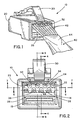
- a modular communication plug connector embodying the concept of the present invention is designated generally by the reference numeral 10 in the accompanying drawings.
- Modular plug 10 is formed of a thermoplastic material and is designed to terminate a plurality of insulated conductors of a twisted pair cable.
- the insulated conductors in signaled pairs are twisted together along their length within the cable to reduce cross talk between conductors 42 and are enclosed within a protective sheath 44 of cable 40.
- the cable 40 generally is stripped of its sheath 44 exposing four twisted wire pair conductors. These eight conductors 42 are then arranged into the proper color sequence, parallel to one another, and inserted into the housing as shown in FIG. 1.
- Connector 10 can also be used to terminate untwisted pair cable, flat cable or any other cable, the conductors of which are formed or can be formed into a planar array.
- Modular plug 10 having a latch 30 is formed as a housing having a front face 20, and a rear cable receiving channel 28 defined by a top wall 12, first and second sidewalls 16, 18, and a bottom wall 14 as can be seen in FIGS. 2 and 3.
- Channel 28 communicates with an array of eight conductor positioning channels 22 extending to the front face 20.
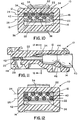
- the conductor positioning channels 22 are separated into an upper plane 24 and a lower plane 26. It is to be noted that as shown in FIG. 2, due to manufacturing constraints the far left conductor of the upper plane is slightly lower. As can be seen in FIGS.
- a plurality of integrally formed ramp surfaces 34, 36 are situated within the cable receiving channel 28 so as to automatically receive and accurately position individual conductors 42 therebetween in the preferred spaced apart two-plane relationship.
- the top ramp surfaces 34 cause alternate conductors 42 to be deflected downward into the lower plane of conductor positioning channels 26.
- the bottom ramps 36 are positioned so as to automatically realign any stray conductors 42 back into the upper plane of conductor positioning channels 24.
- the stripped and aligned conductors 42 are initially inserted against the top interior wall surface 12 which includes a plurality of guide troughs 32 that keep conductors 42 separated and in their proper order. Further insertion guides the conductors 42 to the respective ramp and corresponding conductor positioning channel 22. As can be seen in FIGS. 8 and 9 as the conductors 42 reach the guide ramps 34, 36, upper ramps 34 deflect the alternate conductors 42 downward and into the lower plane 26 of conductor positioning channels 22.
- conductors 42 can be terminated by the contact blades 38 inserted through a plurality of corresponding contact slots 48 and the strain relief 46 applied to the cable 40 within the connector 10 as shown in FIGS. 11 and 12.
- channel 26 extends into connector 10 as far as practicable since having a smaller parallel run of adjacent conductor pairs reduces cross talk. However, a sufficient length of the stripped end of the wires must be maintained to have enough rigidity to be inserted.
- the final staggered disposition of the distal ends of conductors provides a plug connector that has been found to reduce cross talk induced by the connector an amount sufficient to consistently exceed category 5 cross talk performance as specified by the Electronics Industries Association and the Telecommunication Industry Association, EIA/TIA in specification SP-2840, with the plug and cable tested under TSB-67 certification test equipment for category 5 compliance and the plug alone tested under TSB-40 termination component requirements while providing a connector that can be economically manufactured and easily terminated, without the use of a separate wire loading bar, merely by inserting a planar array of conductors into the connector and terminating the plug connector.
- the present invention has been described as used in a modular plug connector, it is to be understood that the present invention would be useful in any type of connector to reduce cross talk in a connector where it is desirable to initially position a substantially planar array of conductors in the connector for termination.
Description
Claims (2)
- A connector for terminating a plurality of conductors of a plurality of conductor pairs, comprising:characterized inA connector housing having a rear cable receiving opening (28) formed by a top wall (12), a bottom wall (14) and a pair of opposing side walls (16, 18); anda plurality of conductor positioning channels (22) separated into an upper plane (24) and a lower plane (26), wherein the conductor positioning channels (22) in the upper plane (24) alternate with the conductor positioning channels (22) in the lower plane (26),
upper ramp surfaces (34) on the top wall (12) aligned with the conductor positioning channels (22) in the lower plane (26) and lower ramp surfaces (36) on the bottom wall (14) aligned with the conductor positioning channels (22) in the upper plane (24), both for guiding alternate conductors (42) into the upper and lower conductor positioning channels (22), respectively. - A connector in accordance with claim 2,
characterized by
alignment means (32) on the inner side of the top wall (12) for maintaining the alignment of the conductors (42) into the respective ramp surfaces (34, 36) during insertion.
Applications Claiming Priority (2)
| Application Number | Priority Date | Filing Date | Title |
|---|---|---|---|
| US08/760,932 US5906503A (en) | 1996-12-06 | 1996-12-06 | Modular plug with automatically staggered wires |
| US760932 | 1996-12-06 |
Publications (3)
| Publication Number | Publication Date |
|---|---|
| EP0847111A2 EP0847111A2 (en) | 1998-06-10 |
| EP0847111A3 EP0847111A3 (en) | 1998-12-09 |
| EP0847111B1 true EP0847111B1 (en) | 2002-03-06 |
Family
ID=25060608
Family Applications (1)
| Application Number | Title | Priority Date | Filing Date |
|---|---|---|---|
| EP97119177A Expired - Lifetime EP0847111B1 (en) | 1996-12-06 | 1997-11-03 | Modular plug with automatically staggered wires |
Country Status (9)
| Country | Link |
|---|---|
| US (1) | US5906503A (en) |
| EP (1) | EP0847111B1 (en) |
| JP (1) | JP4218996B2 (en) |
| CN (1) | CN1127180C (en) |
| AU (1) | AU733594B2 (en) |
| BR (1) | BR9705506A (en) |
| CA (1) | CA2219194A1 (en) |
| DE (1) | DE69710854T2 (en) |
| TW (1) | TW387160B (en) |
Families Citing this family (15)
| Publication number | Priority date | Publication date | Assignee | Title |
|---|---|---|---|---|
| US6017237A (en) * | 1996-08-26 | 2000-01-25 | Sullivan; Robert W. | Twisted-pair data cable with electrical connector attached |
| US6409535B1 (en) * | 1999-02-08 | 2002-06-25 | Stewart Connector Systems, Inc. | Modular electrical plug and plug-cable assembly including the same |
| US6074238A (en) * | 1998-05-15 | 2000-06-13 | Molex Incorporated | Electrical tap connector with spreader means |
| JP2000251963A (en) * | 1999-02-26 | 2000-09-14 | Mitsumi Electric Co Ltd | Small-sized connector |
| US6358092B1 (en) | 1999-07-27 | 2002-03-19 | The Siemon Company | Shielded telecommunications connector |
| TW478662U (en) * | 2000-07-07 | 2002-03-01 | Guann Tau Internat Corp | Improved structure of flat bus line connector |
| US6506077B2 (en) | 2000-07-21 | 2003-01-14 | The Siemon Company | Shielded telecommunications connector |
| US6760607B2 (en) * | 2000-12-29 | 2004-07-06 | Masimo Corporation | Ribbon cable substrate pulse oximetry sensor |
| US9543729B2 (en) * | 2013-08-19 | 2017-01-10 | Sullstar Technologies, Inc | Electrical connector with removable external load bar, and method of its use |
| KR101664304B1 (en) * | 2014-12-16 | 2016-10-10 | 주식회사 유라코퍼레이션 | Connector |
| EP3869635B1 (en) | 2015-08-12 | 2024-03-27 | CommScope Technologies LLC | Electrical plug connector |
| JP6638583B2 (en) * | 2016-07-12 | 2020-01-29 | 株式会社オートネットワーク技術研究所 | Connector and electric connection assembly having the same |
| US10756461B2 (en) | 2017-05-30 | 2020-08-25 | Erico International Corporation | Adapter for splice block openings |
| KR102079004B1 (en) * | 2019-06-27 | 2020-02-19 | 대성씨앤씨(주) | Ground connection apparatus |
| JP7249226B2 (en) * | 2019-07-18 | 2023-03-30 | 日本航空電子工業株式会社 | Connectors and cable harnesses |
Family Cites Families (17)
| Publication number | Priority date | Publication date | Assignee | Title |
|---|---|---|---|---|
| US4002392A (en) * | 1973-07-06 | 1977-01-11 | Western Electric Company, Inc. | Electrical connecting devices for terminating cords |
| US4054350A (en) * | 1976-12-03 | 1977-10-18 | Western Electric Company, Inc. | Modular plug for terminating cord having non-planar array of conductors |
| US4160575A (en) * | 1978-02-24 | 1979-07-10 | Vari-Tronics Co. | Telephone cord connector |
| US4143935A (en) * | 1978-03-13 | 1979-03-13 | International Telephone And Telegraph Corp. | Electrical connector |
| US4211462A (en) * | 1979-01-22 | 1980-07-08 | Stewart Stamping Corporation, A Division Of Insilco Corp. | Electrical connector for termination cords with improved locking means |
| US4601530A (en) * | 1984-08-30 | 1986-07-22 | Amp Incorporated | Electrical connector and wire assembly method |
| US4607905A (en) * | 1985-04-18 | 1986-08-26 | Brand-Rex Company | Modular plug |
| US4650269A (en) * | 1985-09-16 | 1987-03-17 | At&T Information Systems Inc. | Modular plug connector |
| US4758536A (en) * | 1986-09-18 | 1988-07-19 | Amp Incorporated | Receptacle for premise wiring system |
| US5147215A (en) * | 1990-03-08 | 1992-09-15 | Amp Incorporated | Connector with integral wire management system |
| JPH0433280U (en) * | 1990-07-16 | 1992-03-18 | ||
| US5057038A (en) * | 1990-09-24 | 1991-10-15 | Molex Incorporated | Shielded electrical connection |
| US5194014A (en) * | 1992-05-20 | 1993-03-16 | Stewart Connector Systems, Inc. | Cable connector and contact terminal therefor |
| US5571035A (en) * | 1994-10-31 | 1996-11-05 | The Whitaker Corporation | Divergent load bar |
| US5605469A (en) * | 1995-01-05 | 1997-02-25 | Thomas & Betts Corporation | Electrical connector having an improved conductor holding block and conductor shield |
| US5593314A (en) * | 1995-01-31 | 1997-01-14 | The Whitaker Corporation | Staggered terminal array for mod plug |
| US5624274A (en) * | 1995-11-07 | 1997-04-29 | International Connectors And Cable Corporation | Telephone connector with contact protection block |
-
1996
- 1996-12-06 US US08/760,932 patent/US5906503A/en not_active Expired - Lifetime
-
1997
- 1997-10-24 CA CA002219194A patent/CA2219194A1/en not_active Abandoned
- 1997-10-28 CN CN97122402A patent/CN1127180C/en not_active Expired - Lifetime
- 1997-11-03 EP EP97119177A patent/EP0847111B1/en not_active Expired - Lifetime
- 1997-11-03 DE DE69710854T patent/DE69710854T2/en not_active Expired - Fee Related
- 1997-11-13 JP JP31228497A patent/JP4218996B2/en not_active Expired - Lifetime
- 1997-11-13 AU AU45226/97A patent/AU733594B2/en not_active Ceased
- 1997-11-15 TW TW086117096A patent/TW387160B/en not_active IP Right Cessation
- 1997-12-02 BR BR9705506-9A patent/BR9705506A/en not_active IP Right Cessation
Also Published As
| Publication number | Publication date |
|---|---|
| US5906503A (en) | 1999-05-25 |
| JP4218996B2 (en) | 2009-02-04 |
| BR9705506A (en) | 1999-09-21 |
| CN1127180C (en) | 2003-11-05 |
| CN1184348A (en) | 1998-06-10 |
| EP0847111A2 (en) | 1998-06-10 |
| TW387160B (en) | 2000-04-11 |
| AU733594B2 (en) | 2001-05-17 |
| DE69710854D1 (en) | 2002-04-11 |
| EP0847111A3 (en) | 1998-12-09 |
| DE69710854T2 (en) | 2002-11-28 |
| MX9709303A (en) | 1998-10-31 |
| JPH10233240A (en) | 1998-09-02 |
| AU4522697A (en) | 1998-06-11 |
| CA2219194A1 (en) | 1998-06-06 |
Similar Documents
| Publication | Publication Date | Title |
|---|---|---|
| US5888100A (en) | Twisted pair cable and connector assembly | |
| EP0766350B1 (en) | Modular plug connector | |
| EP0870347B1 (en) | Patch cord connector | |
| EP0971444B1 (en) | Modular plug having a circuit board | |
| US6561838B1 (en) | Connector plug and insert for twisted pair cables | |
| US6402559B1 (en) | Modular electrical plug, plug-cable assemblies including the same, and load bar and terminal blade for same | |
| EP0847111B1 (en) | Modular plug with automatically staggered wires | |
| EP1198867B1 (en) | Shielded telecommunications connector | |
| US6663419B2 (en) | Reduced crosstalk modular plug and patch cord incorporating the same | |
| US20080014801A1 (en) | Wire guide and connector assembly using same | |
| US7249962B2 (en) | Connector assembly | |
| US6409544B1 (en) | Network data transmission cable connector | |
| MXPA04003148A (en) | Shielded telecommunications connector. | |
| EP0716477B1 (en) | Modular plug for high speed data transmission | |
| US7722410B2 (en) | Plug | |
| US6368143B1 (en) | Modular plug with two piece housing | |
| EP0590796B1 (en) | Mixed coaxial connector | |
| US5984713A (en) | Termination structure for modular telephone plugs | |
| EP1263092B1 (en) | Network data transmission cable connector | |
| MXPA97009303A (en) | Modular plug with automatically alternate wires |
Legal Events
| Date | Code | Title | Description |
|---|---|---|---|
| PUAI | Public reference made under article 153(3) epc to a published international application that has entered the european phase |
Free format text: ORIGINAL CODE: 0009012 |
|
| AK | Designated contracting states |
Kind code of ref document: A2 Designated state(s): DE FR GB IT |
|
| AX | Request for extension of the european patent |
Free format text: AL;LT;LV;MK;RO;SI |
|
| PUAL | Search report despatched |
Free format text: ORIGINAL CODE: 0009013 |
|
| AK | Designated contracting states |
Kind code of ref document: A3 Designated state(s): AT BE CH DE DK ES FI FR GB GR IE IT LI LU MC NL PT SE |
|
| AX | Request for extension of the european patent |
Free format text: AL;LT;LV;MK;RO;SI |
|
| 17P | Request for examination filed |
Effective date: 19990413 |
|
| AKX | Designation fees paid |
Free format text: DE FR GB IT |
|
| 17Q | First examination report despatched |
Effective date: 20000309 |
|
| GRAG | Despatch of communication of intention to grant |
Free format text: ORIGINAL CODE: EPIDOS AGRA |
|
| GRAG | Despatch of communication of intention to grant |
Free format text: ORIGINAL CODE: EPIDOS AGRA |
|
| GRAH | Despatch of communication of intention to grant a patent |
Free format text: ORIGINAL CODE: EPIDOS IGRA |
|
| GRAH | Despatch of communication of intention to grant a patent |
Free format text: ORIGINAL CODE: EPIDOS IGRA |
|
| REG | Reference to a national code |
Ref country code: GB Ref legal event code: IF02 |
|
| GRAA | (expected) grant |
Free format text: ORIGINAL CODE: 0009210 |
|
| RIC1 | Information provided on ipc code assigned before grant |
Free format text: 7H 01R 24/00 A, 7H 01R 24/02 B, 7H 01R 24/18 B, 7H 01R 12/24 B, 7H 01R 12/16 B, 7H 01R 12/18 B, 7H 01R 12/20 B, 7H 01R 12/22 B |
|
| AK | Designated contracting states |
Kind code of ref document: B1 Designated state(s): DE FR GB IT |
|
| REF | Corresponds to: |
Ref document number: 69710854 Country of ref document: DE Date of ref document: 20020411 |
|
| ET | Fr: translation filed | ||
| PLBE | No opposition filed within time limit |
Free format text: ORIGINAL CODE: 0009261 |
|
| STAA | Information on the status of an ep patent application or granted ep patent |
Free format text: STATUS: NO OPPOSITION FILED WITHIN TIME LIMIT |
|
| 26N | No opposition filed |
Effective date: 20021209 |
|
| PG25 | Lapsed in a contracting state [announced via postgrant information from national office to epo] |
Ref country code: IT Free format text: LAPSE BECAUSE OF NON-PAYMENT OF DUE FEES Effective date: 20051103 |
|
| PGFP | Annual fee paid to national office [announced via postgrant information from national office to epo] |
Ref country code: DE Payment date: 20081103 Year of fee payment: 12 |
|
| PGFP | Annual fee paid to national office [announced via postgrant information from national office to epo] |
Ref country code: FR Payment date: 20081112 Year of fee payment: 12 |
|
| REG | Reference to a national code |
Ref country code: FR Ref legal event code: ST Effective date: 20100730 |
|
| PG25 | Lapsed in a contracting state [announced via postgrant information from national office to epo] |
Ref country code: FR Free format text: LAPSE BECAUSE OF NON-PAYMENT OF DUE FEES Effective date: 20091130 |
|
| PG25 | Lapsed in a contracting state [announced via postgrant information from national office to epo] |
Ref country code: DE Free format text: LAPSE BECAUSE OF NON-PAYMENT OF DUE FEES Effective date: 20100601 |
|
| PGFP | Annual fee paid to national office [announced via postgrant information from national office to epo] |
Ref country code: GB Payment date: 20161128 Year of fee payment: 20 |
|
| REG | Reference to a national code |
Ref country code: GB Ref legal event code: PE20 Expiry date: 20171102 |
|
| PG25 | Lapsed in a contracting state [announced via postgrant information from national office to epo] |
Ref country code: GB Free format text: LAPSE BECAUSE OF EXPIRATION OF PROTECTION Effective date: 20171102 |