EP0970626A1 - A plurality of wrappers filled with tobacco for making cigarettes - Google Patents
A plurality of wrappers filled with tobacco for making cigarettes Download PDFInfo
- Publication number
- EP0970626A1 EP0970626A1 EP99121159A EP99121159A EP0970626A1 EP 0970626 A1 EP0970626 A1 EP 0970626A1 EP 99121159 A EP99121159 A EP 99121159A EP 99121159 A EP99121159 A EP 99121159A EP 0970626 A1 EP0970626 A1 EP 0970626A1
- Authority
- EP
- European Patent Office
- Prior art keywords
- tobacco
- filled
- strand
- casings
- casing
- Prior art date
- Legal status (The legal status is an assumption and is not a legal conclusion. Google has not performed a legal analysis and makes no representation as to the accuracy of the status listed.)
- Granted
Links
- 241000208125 Nicotiana Species 0.000 title claims abstract description 158
- 235000002637 Nicotiana tabacum Nutrition 0.000 title claims abstract description 158
- 235000019504 cigarettes Nutrition 0.000 title claims abstract description 65
- 239000000123 paper Substances 0.000 claims abstract description 28
- 238000004806 packaging method and process Methods 0.000 claims abstract description 25
- 239000011111 cardboard Substances 0.000 claims abstract description 5
- 239000004033 plastic Substances 0.000 claims abstract description 5
- 229920003023 plastic Polymers 0.000 claims abstract description 5
- 239000011087 paperboard Substances 0.000 claims abstract 2
- 238000004519 manufacturing process Methods 0.000 claims description 10
- 238000012546 transfer Methods 0.000 description 25
- 230000007246 mechanism Effects 0.000 description 6
- 238000005096 rolling process Methods 0.000 description 6
- 230000004048 modification Effects 0.000 description 5
- 238000012986 modification Methods 0.000 description 5
- 244000061176 Nicotiana tabacum Species 0.000 description 4
- 230000008901 benefit Effects 0.000 description 4
- 230000008878 coupling Effects 0.000 description 4
- 238000010168 coupling process Methods 0.000 description 4
- 238000005859 coupling reaction Methods 0.000 description 4
- 238000012545 processing Methods 0.000 description 4
- 238000003860 storage Methods 0.000 description 4
- 230000015572 biosynthetic process Effects 0.000 description 3
- 238000000034 method Methods 0.000 description 3
- 230000000391 smoking effect Effects 0.000 description 3
- 235000019505 tobacco product Nutrition 0.000 description 3
- 230000009471 action Effects 0.000 description 2
- 238000010276 construction Methods 0.000 description 2
- 239000003292 glue Substances 0.000 description 2
- 230000006872 improvement Effects 0.000 description 2
- 239000000463 material Substances 0.000 description 2
- 230000008569 process Effects 0.000 description 2
- 238000011144 upstream manufacturing Methods 0.000 description 2
- 239000000853 adhesive Substances 0.000 description 1
- 230000001070 adhesive effect Effects 0.000 description 1
- 239000002390 adhesive tape Substances 0.000 description 1
- 230000006399 behavior Effects 0.000 description 1
- 150000001875 compounds Chemical class 0.000 description 1
- 238000011109 contamination Methods 0.000 description 1
- 238000005520 cutting process Methods 0.000 description 1
- 238000011161 development Methods 0.000 description 1
- 230000018109 developmental process Effects 0.000 description 1
- 238000006073 displacement reaction Methods 0.000 description 1
- 230000000694 effects Effects 0.000 description 1
- 239000003344 environmental pollutant Substances 0.000 description 1
- 210000003746 feather Anatomy 0.000 description 1
- 239000000945 filler Substances 0.000 description 1
- 230000003993 interaction Effects 0.000 description 1
- 231100000719 pollutant Toxicity 0.000 description 1
- 239000007787 solid Substances 0.000 description 1
Images

Classifications
-
- A—HUMAN NECESSITIES
- A24—TOBACCO; CIGARS; CIGARETTES; SIMULATED SMOKING DEVICES; SMOKERS' REQUISITES
- A24C—MACHINES FOR MAKING CIGARS OR CIGARETTES
- A24C5/00—Making cigarettes; Making tipping materials for, or attaching filters or mouthpieces to, cigars or cigarettes
- A24C5/40—Hand-driven apparatus for making cigarettes
- A24C5/42—Pocket cigarette-fillers
-
- A—HUMAN NECESSITIES
- A24—TOBACCO; CIGARS; CIGARETTES; SIMULATED SMOKING DEVICES; SMOKERS' REQUISITES
- A24C—MACHINES FOR MAKING CIGARS OR CIGARETTES
- A24C5/00—Making cigarettes; Making tipping materials for, or attaching filters or mouthpieces to, cigars or cigarettes
- A24C5/40—Hand-driven apparatus for making cigarettes
Definitions
- the invention relates to a for the production of cigarettes certain variety of tobacco-filled strand casings claims 1, 8 and 10.
- Cigarettes As a fundamentally different kind of self-production of Cigarettes are known as self-stuffing cigarettes.
- a plug-in nozzle for attaching and plugging on an empty cigarette tube provided.
- the bale chamber is ended by a piston-like tobacco discharge valve limited, by means of which the tobacco supply from the Bale chamber can be transferred into the cigarette tube (cf. e.g. DE 2 833 681).
- a piston-like tobacco discharge valve limited, by means of which the tobacco supply from the Bale chamber can be transferred into the cigarette tube.
- These well-known tamping devices have become proven more or less well in practice. It is their responsibility however, the disadvantage that a when filling the bale chamber certain contamination of the user's hands as well as the Environment with tobacco residues or crumbling should not be avoided can, which is perceived as bothersome and the user often discourages the use of such a device. After all, manual filling is always a constant filling level of the bale chamber and thus the Cigarette tube not possible.
- self-stuffed cigarettes are characterized by different smoking behavior, namely different Train, taste and differently long smoking time.
- the self-stuffed cigarette behaves similarly to the rolling cigarette.
- the pollutant content is also the self-stuffed in a conventional manner Cigarette very different and uncontrolled accordingly the different fill levels of the cigarette tube.
- Cigarette stopper for the self - production of cigarettes by the Proposed consumer, which is characterized by an as such a non-smokable prefabricated product in the form of a prefabricated tobacco cartridge, consisting of a open at the front, with its diameter of Cigarette paper sleeve adapted to the finished cigarettes Strand casing and a strand-like, each one A portion of tobacco corresponding to a cigarette, which by an assigned, the inner diameter of the strand casing customized pistons from the strand casing into an empty one Cigarette paper tube is transferable.
- This tobacco product is suitable for use in conjunction with conventional self-filling cigarette tubes as well Compound with conventional self-rolling papers.
- this Proposal will give the consumer a precisely dosed, namely the filling quantity of a conventional, industrial Corresponding quantity of tobacco in the form of a Cigarette tobacco cartridge provided, whose Tobacco filling in a prefabricated cigarette tube commercial type is convertible.
- a Cigarette tobacco cartridge provided, whose Tobacco filling in a prefabricated cigarette tube commercial type is convertible.
- the object of the invention is a Varieties of tobacco intended for making cigarettes filled strand sleeves to create better handling in the manufacture of cigarettes at the same time Improvement in the manufacturing quality of cigarettes can guarantee. Furthermore, a particularly suitable one Tobacco unit of use are provided that deal with a system for making cigarettes based of cigarette paper tubes.
- a second proposed solution according to the invention for solving the mentioned task results from claim 8, wherein a advantageous embodiment of this second proposed solution emerges from the claim 9.
- the strand casings filled with tobacco according to the present Invention have the advantage that they are due to their as Unit held together shape can be handled very conveniently can and also because of their strand casing connection be kept dimensionally stable.
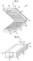
- FIG. 1 to 5 is a first embodiment of a Device 10 for processing an invention provided variety shown in tobacco portions.
- This Device comprises a housing with a lower and a upper housing part 14 or 12.
- the two housing parts 12, 14 are hinged or articulated with one another on one side connected.
- the hinge joint has the reference number 64 featured. Accordingly, the two housing parts 12, 14 apart (Fig.1) and collapsed (Fig.2) become. When folded, the two are lying Housing parts 12 and 14 exactly one another and form one cuboid block (Fig. 2a and 2b).
- the two housing parts have 12, 14 on their sides facing each other Longitudinal grooves 22 which are separated from one another by longitudinal webs are.
- the longitudinal grooves 22 each run parallel to Hinge joint axis 64 and each have one semicircular cross section.
- Each longitudinal groove 22 on the inside of the lower housing part 14 is a longitudinal groove 22 assigned to the inside of the upper housing part 12. The the same applies to those arranged between the longitudinal grooves 22 Longitudinal webs. If the two housing parts 12 and 14 folded up, form two facing each other Longitudinal grooves 22 a receiving space 23 with an approximately circular Cross-section.
- the inner diameter of each recording room 23 is about the same, slightly larger or slightly smaller than the outside diameter of a strand casing filled with tobacco 150.
- the casing 150 contains a corresponding amount of tobacco the amount of tobacco in a conventional cigarette.
- the Inner diameter of the strand casing 150 corresponds approximately to that Inner diameter of the tobacco storage room of a prefabricated Cigarette paper tube. Accordingly, from the Strand casing 150 of the tobacco or tobacco rod essentially without changing the diameter in the tobacco storage room transfer assigned cigarette paper tube.
- the length of the Strand envelope 150 or that held together by this Strands of tobacco can be the same or, preferably, slightly larger than the length of the tobacco containment space associated with the Cigarette paper tube.
- strand casing 150 either of smokable or non-smokable material can exist.
- the strand casing must be like this breathable, e.g. be perforated that the tobacco rod is not smokable outside a cigarette paper tube.
- the housing 11 In the opened state of the housing 11 can in the Longitudinal grooves 22 of the lower housing part 14 filled with tobacco Strand sleeves 150 are inserted. After all or part the longitudinal grooves 22 of the lower housing part with a tobacco filled strand casing 150 are filled, the housing 11 folded up. Support is provided in this state of the casing 150 on the inner walls of each other assigned longitudinal grooves 22 or by two receiving spaces 23 which are assigned to one another and which are assigned to longitudinal grooves. For a better hold of the strand envelopes 150 within the Longitudinal grooves 22 formed receiving spaces 23 can Surfaces of the longitudinal grooves 22 may be roughened. Are at the front the receiving spaces 23 formed by the longitudinal grooves 22 as well like the strand sheaths 150 open.
- top Housing part 12 At the top 28 of the top Housing part 12 are two parallel to each other Rows of spaced-apart trough-like Wells 26 formed.
- the two rows of trough-like depressions 26 each extend approximately perpendicular to the longitudinal extent of the longitudinal grooves 22 or receiving spaces 23 defined by the longitudinal grooves 22 mutual distance of the trough-like depressions 26 corresponds to the distance between the longitudinal central axes of the receiving spaces 23 defined by the longitudinal grooves 22.
- the upper housing part 12 has two guides appeared on 24, each parallel to the two Rows of trough-like depressions 26, i.e. Likewise perpendicular to the longitudinal central axes of the receiving spaces 23 he stretch.
- These guide rails 24 are used to hold and Longitudinal guidance of a mountable on the upper housing part 12 Tobacco transfer element 40 according to FIGS. 3 and 4 or 5.
- the tobacco transfer element 40 is approximately U-shaped Component with a connecting web 42 and two Legs 44, on the inner sides facing each other Guide grooves 46 are formed, which with the mentioned Guide rails 24 on the upper housing part 12 of the housing 11 work together. Accordingly, it is Tobacco transfer element 40 along the housing side Guide rails 24 slidable on the upper housing part 12.
- a rod 48 is axially displaceably mounted, and that parallel to the web 42.
- the rod 48 has on his inner, i.e. facing the opposite leg 44 End a piston 50 on, the diameter slightly is smaller than the inner diameter of the strand casing 150.
- Am a handle 52 is arranged on the opposite outer end, with which the rod 48 can be moved axially.
- the other leg namely the one on the left in FIGS. 3 and 4 Leg 44 has one with rod 48 or piston 50 aligned bore, the inside diameter of which is somewhat larger is 50 as the outer diameter of the piston.
- This bore is continued to the outside through an adapter 60.
- the plug-in nozzle is within one Recess accessible from above, so that without disability in a conventional manner on the plug-in nozzle 60 Cigarette paper sleeve can be put on.
- the plug-in nozzle 60 in a conventional manner Clamping mechanism for an attached cigarette paper tube assigned.
- This clamping mechanism is conventional Clamping plungers arranged diametrically to the plug-in nozzle 60 62 with push buttons 58 accessible from the outside.
- the clamping plungers 62 together with push buttons 58 can be against the effect of a elastic element, in particular a spring against the Push on fitting 60.
- the tobacco transfer element 40 After part or all of the receiving spaces 23 with one Tobacco portion of the kind described above and the casing 11 are closed, the tobacco transfer element 40 successively the receiving spaces 23 or the strand casings 150 assigned.
- the Push-on nozzle 60 in a conventional manner Cigarette paper sleeve attached and using the clamping plunger 62 recorded.
- the rod 48 together with the piston 50 by means of the handle 52 axially in the housing or in the respective Receiving space 23 inserted.
- the piston 50 is the tobacco or tobacco rod located in the casing 150 through the plug-in nozzle 60 into the Cigarette paper tube or their tobacco receiving room transferred.
- the rod 48 is then velvety by means of the handle 52 Piston 50 withdrawn again until the piston 50 outside the Collision area with the housing 11 is.
- the one with tobacco Filled cigarette is made in a conventional manner by the Push-on grommet 60 after release by the clamping plunger 62 deducted.
- the tobacco transfer member 40 is along the Guide rails 24 shifted into a next latching position, in which the rod 48 together with the piston 50 and the push-on nozzle 60 again in alignment with the next assigned recording room 23 lie in which a strand casing filled with tobacco or Portion of tobacco.
- the empty strand envelopes 150 will away.
- the described method can then start again be started until the user has a sufficient number of Made cigarettes.
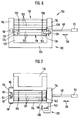
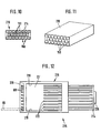
- 6 to 9 is an alternative device of the here shown in question.
- This has a housing in shape a U-shaped frame 112 with a base plate 113 and two upright legs 114 between them two legs 114, two grooved rollers 118, 119 are rotatable stored, according to Fig. 6 over and parallel to each other.
- the distance between the two grooved rollers 118, 119 is so chosen so that the lateral surfaces almost touch each other Not shown gear train within one of the two Leg 114 are the two grooved rollers 118, 119 such coupled with each other so that they turn turn counter to each other.
- each grooved roller 118, 119 132 Longitudinal grooves are provided in the lateral surface of each grooved roller 118, 119 132 each with an approximately semicircular cross section educated.
- the longitudinal grooves 132 are separated from one another by longitudinal webs Cut.
- the longitudinal grooves of both grooved rollers each have the same angular distance from each other.
- the gear Coupling between the two grooved rollers 118, 119 is such that when the same rotates between two in the area of plane extending through the axes of rotation of both rollers facing each other a receiving space for one with Strand casing 150 filled with tobacco with an approximately circular shape Cross section is formed. This so defined Recording space 23 is open on both ends.
- the one The end face is the already described rod 48 with piston and Handle 52 assigned, while on the other end already in connection with the first embodiment described plug-in nozzle 60 with clamping mechanism 62, 58 is arranged.
- the rod 48 is in one of the two legs 114 (in FIGS. 6 and 7 the right leg 114) axially slidably mounted.
- the fitting is accordingly 60 formed on the other leg 114, and likewise again within a recess accessible from above 158.
- roller pair 118, 119 a variety of tobacco-filled Strand sleeves 150 receiving magazine 116 like a upstream inclined slide, so that when turning the two grooved rollers 118, 119 each filled with tobacco Strand cover 150 automatically from the magazine 116 in the through longitudinal grooves facing each other define receiving space 23 slips.
- Receiving space 23 are further strand wipers or Sub-casing throw-up elements 124 and 136 downstream, the when turning the two grooving rollers one from the receiving space 23 released and emptied strand casing 150 from the Loosen the longitudinal grooves 132 of the grooved rollers 118 or 119.
- the Ejection elements 124, 136 are each in circumferential grooves 120 of the upper and lower grooving arms engaging, which the ejection elements 124 associated with lower grooved roller 119 in one piece with a holding plate 122 fastened to the frame 112 are executed.
- the ejection elements 136 that of the upper Grooved roller 118 are assigned, are one-story with a Connection plate or a connecting plate 134 formed, which is mounted on the two legs 114 of the frame 112.
- one is with the lower one Grooved roller 119 engageable actuator for Rotation of the same or both grooved rollers 118, 119 provided.
- the actuator is one with the lower one Grooved roller 119 engageable pivot lever 126, the Pivot axis with the axis of rotation of the lower grooved roller 119 coincides.
- the pivot lever 126 comprises a latch 140, under the action of a spring 160 either with the Longitudinal grooves 132 of the lower grooved roller 119 or with the Gears of the coupling gear mentioned is engaged and out of engagement against the action of this spring 160 can be brought.
- locking means 142 may also be provided. Only one of these is shown in FIG. 7, namely in Form of a spring-loaded detent ball, the front in a longitudinal groove 132 of the upper grooved roller 118 here intervenes. The intervention takes place in a specific case the end face of a longitudinal groove of the upper grooved roller 118 locking mechanism described can also the lower grooved roller or be assigned to both grooved rollers. In the specific case However, the assignment to only one grooved roller is sufficient the described gear connection of both grooved rollers 118, 119.
- the mode of operation is the last one described embodiment as follows:
- the magazine 116 comes with a variety of tobacco filled strand shells 150 or correspondingly trained stick-like tobacco portions filled. These portions of tobacco can either be loose from each other or together be connected to a kind of tobacco cartridge belt.
- the bottom one The tobacco portion lies on the two grooved rollers 118, 119 in this way indicates that when both grooved rollers rotate in the direction of the arrows 154 each a portion of tobacco from the dividers of the Recording space 23 upstream longitudinal grooves of the two Grooving rollers are detected and taken away.
- the rotation of the both grooved rollers 118, 119 is by the pivot lever 126 and the bolt 140 assigned to it in the above described way achieved.
- the pivoting movement of the Swivel lever 126 is referenced 128 in FIG. 7 indicated.
- the cigarette paper tube filled with tobacco is from the Detachable grommet removed.
- the grooving rollers 118, 119 by one another step can be rotated by means of the pivot lever 126 with the formation of a new recording room 23, in which then there is a new portion of tobacco.
- the tobacco portion is defined by a Strand casing 150 and a string-like tobacco filling 151 Strand casing 150 is so permeable to air that the Portion of tobacco outside of a close-fitting Cigarette paper tube is not smokable.
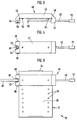
- a third alternative for a processing device a multitude of Portions of tobacco is schematic in Figs. 10-12 shown. Accordingly, in a box or Outer packaging 210 a variety of parallel side and one above the other and close together, each with tobacco filled strand casings 150 or tobacco portions provided.
- the strand sleeves 150 are preferably by adhesive dots interconnected so that they are within the Support the outer packaging 210.
- the outside Strand sleeves 150 are on the inside of the outer packaging 210 fixed, preferably also bonded to this. Consequently is a compact structure consisting of a group of Servings of tobacco of the type described, within a Outer packaging 210 lies.
- 10 and 11 is the Box or outer packaging 210 is open on the front. Of course, the box or outer packaging is before use 210 also closed at the front, both moisture and aroma tight.
- the above group of tobacco portions is a pre direction assigned 215, which is shown in Fig. 12 in plan view is posed.
- the device has one in a housing 216 trained receiving space 231, the dimensions of the The dimensions of the box or outer packaging 210 correspond.
- the outer packaging 210 including tobacco portions 150, 151 are positioned from above in the receiving space 231.
- the Receiving space 231 are a plurality of through holes and the associated push-on sleeves 60 or arranged. Each plug-in nozzle is aligned with the position of one Portion of tobacco inside the box or outer packaging 210.
- there is one on the opposite side Tobacco transfer device with a plurality of bars 222 intended.
- the Number of rods 222 and the number of slip-on sleeves 60 corresponds to the number of arranged in the outer packaging 210 Servings of tobacco 150, 151.
- a yoke-like connecting element 224 Handle 226 connected to a rod unit, see above that the bars 222 together, i.e. as a whole through with Tobacco-filled strand casings 150 can be moved through. Accordingly, to produce a group of Cigarettes on all push-on nozzles 60 Cigarette paper sleeves attached, using a clamping wedge or the like is held on the plug-in sleeves. Then becomes an outer packaging filled with tobacco portions 150, 151 210, whose end faces have previously been opened, in Recording room 23 positioned. Then the rod unit by means of the handle 226 axially into the receiving space 231 pushed in.
- the simultaneous transfer takes place of the tobacco from all the casing 150 in the assigned Cigarette paper tubes or their tobacco storage rooms. Then the rod unit is pulled back until the outer packaging 210 is free for removal. The one with tobacco filled cigarettes are from the slip-on nozzles 60 removed after the described clamping will be annulled. The mutual support of the strand casings 150 within the outer packaging 210 is sufficient for stability for the tobacco transfer process.
- the rod unit can Lever mechanism or the like can be assigned.
- the inner side walls of the accommodating space 231 is shown in FIG. 12 marked with the reference number 219. This is because of them two lateral narrow sides of the outer packaging 210.
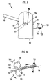
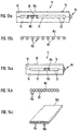
- FIG. 13a shows a modified embodiment of one Device corresponding to that according to Figures 1 to 5 shown with closed housing in side view.
- This Embodiment differs from that according to the Figures 1 to 5 on the one hand in that the lower Housing part 14 facing the inner wall of the receiving space 23 for the casing 150 filled with tobacco is flat.
- the corresponding inner wall is the floor one on the inside of the upper housing part 12 trained, parallel to the housing hinge axis 64th extending flat groove.
- FIG. 13a shows a modified embodiment of one Device corresponding to that according to Figures 1 to 5 shown with closed housing in side view.
- FIG. 14a shows a construction modified compared to the device according to FIG. 13a, the modification being that the longitudinal grooves 22 on the inside of the lower housing part 14 lie directly next to one another.
- the advantage of this constructive modification is that, in a corresponding manner, the strand casings filled with tobacco can also be placed close together within the receiving space 23, with the result of an additional mutual, lateral support.
- the corresponding belt of tobacco casing filled is shown in Figures 14b and 14c.
- the casing 150 filled with tobacco 151 is arranged on one side of a connecting strip 153, preferably glued on.
- the connecting strips 123 can be omitted if the strand casings filled with tobacco are directly glued lengthways. It should only be ensured that a unit of use of at least 2 interconnected strand casings, each filled with tobacco, is available, which - as indicated in FIG. 14 a - can then be placed within the device according to FIG. 14 a.
- the fixed connection between at least two strand casings filled with tobacco has the advantage of easier, in particular faster placement within a device according to FIG. 13a or 14a.
- a belt of tobacco-filled casing can also be used in the device according to FIGS. 1 to 5. Only then would the connecting strip between adjacent strand casings have to extend approximately in the area of their common central plane.
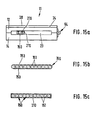
- FIGS. 1 to 5 are constructive Modification of a device according to FIGS. 1 to 5 noted, as shown in Figure 15a in schematic pages view is shown.
- the Recording space 15a limited only by flat walls.
- the receiving space 23 becomes parallel in itself to the housing hinge axis 64 extending flat grooves on the sides facing each other from the top and bottom Housing part 12 and 14 formed. It is also conceivable just to the inside of the upper or lower housing part a little provide deeper shallow groove while the associated Boundary wall on the inside of the other housing part is consistently plan.
- Figures 15b and 15c are for the use of 15a designed particularly advantageously Straps of strand casings 150 filled with tobacco 151 each in Front view shown.
- everyone includes Strand belt eleven strand casings filled with tobacco.
- the scope such a unit of use is a matter of course variable.
- Each strand belt preferably comprises 7, 10 or 12 Strand casings or portions of tobacco filled with tobacco.
- 15b is thereby characterized in that the string casings filled with tobacco between an upper and a lower connecting strip 153 made of plastic, paper or thin cardboard and connected to the connecting strips 153, in particular are glued. Additional or alternative is a glue the string casings filled with tobacco along them Contact lines conceivable.
- FIG. 15c those with tobacco 151 filled casing 150 within a tube-like Outer packaging 210 placed.
- the outer packaging 210 is in accordance with Art of a flat cuboid. Before use of course, the end faces of this outer packaging 210 closed. For the purposes of those described above The end faces are then removed from the tobacco transfer. Then the outer packaging is filled with tobacco Strand sleeves in the receiving space 23 of the device according to the figure 15a. Using the above Tobacco transfer element can then transfer tobacco in each assigned cigarette paper tube.
- trough-like recesses 26 at the top of the upper Housing part 12 as well as in the embodiment according to the Figures 1 to 5 each have a groove-like longitudinal groove 22 on the Assigned inside of the lower housing part 14.
- 15a is the distance between neighboring trough-like recesses 26 each row of these by the center distance between the individual strand casings filled with tobacco within the each used strand belt determined.
- both the longitudinal grooves 132 and also the separators between adjacent longitudinal grooves 132 on the one hand and the connecting strip 153 on the other it is also conceivable without separating the Connecting strips the tobacco-filled strand casings successively into and into the receiving space 23 To move tobacco transfer out of this too.
- the connecting strip supports this case of course, the subsequent promotion of tobacco-filled Strand casings at the correct distance according to the Angular distance of the longitudinal grooves 132.
Landscapes
- Packaging Of Annular Or Rod-Shaped Articles, Wearing Apparel, Cassettes, Or The Like (AREA)
- Manufacturing Of Cigar And Cigarette Tobacco (AREA)
Abstract
Description
Die Erfindung betrifft eine zur Herstellung von Zigaretten bestimmte Vielzahl von mit Tabak gefüllten Stranghüllen nach den Ansprüchen 1, 8 und 10.The invention relates to a for the production of cigarettes certain variety of tobacco-filled strand casings claims 1, 8 and 10.
Die Herstellung von Zigaretten durch den Verbraucher ist in mannigfachen Formen seit langer Zeit bekannt. Dies gilt vor allem für das sogenannte Selbstdrehen von Zigaretten unter Verwendung von mit Klebrandgummierung versehenen Zigarettenpapier-Blättchen. Das Selbstdrehen von Zigaretten erfordert eine gewisse manuelle Geschicklichkeit und Zeitaufwand. Die Zigaretten fallen selbst bei geübten Selbstdrehern hinsichtlich Größe (Durchmesser), Festigkeit (Prallheit) und Füllungsgrad über die Länge der Zigarette hin stark unterschiedlich aus und bilden nur einen primitiven Ersatz für industriell hergestellte Zigaretten. Nachteilig ist beim manuellen Selbstdrehen auch das unvermeidliche Verbröseln von Tabak, worunter auch die Tabakausbeute leidet. Dieselben Probleme - wenn auch vermindert - treten bei Verwendung von Selbstdreh-Geräten auf. Eine Erleichterung für das Selbstdrehen von Zigaretten erhoffte man sich offensichtlich durch die Bereitstellung eines Tabakerzeugnisses gemäß der NL-H-6703935, nämlich bestehend aus einer durch Tabakfüllung einer fertigen Zigarette angepaßten Tabakportion, deren Mantelfläche aus einer Umhüllung aus vollständig durch Rauchen konsumierbaren Material gebildet ist, wobei die Umhüllung so luftdurchlässig ist, daß die Tabakportion als solche nicht wie eine Zigarette rauchbar ist. Um diese Tabakportion sollte unter Herstellung einer rauchbaren Zigarette ein herkömmliches Zigarettenpapier-Blättchen herumgewickelt und in an sich bekannter Weise verklebt werden.The production of cigarettes by the consumer is in manifold forms known for a long time. This applies before all for the so-called self rolling of cigarettes under Use of rubber coated with adhesive tape Rolling papers. The rolling of cigarettes requires some manual dexterity and Time expenditure. The cigarettes fall even when practiced Self-turning in terms of size (diameter), strength (Plumpness) and degree of filling over the length of the cigarette very different and form only a primitive Replacement for industrially manufactured cigarettes. The disadvantage is with manual turning, the inevitable crumbling of tobacco, which also affects the tobacco yield. The same Problems - albeit reduced - occur when using Self-rotating devices on. A relief for that Obviously, people hoped to roll their own cigarettes by providing a tobacco product according to NL-H-6703935, namely consisting of one by tobacco filling manufacture customized tobacco portion, the outer surface from a wrapper made entirely of smoking consumable material is formed, the wrapping so is permeable to air that the tobacco portion as such does not like a cigarette is smokable. To this portion of tobacco should be under Making a smokable cigarette a conventional one Rolling cigarette papers around and in itself known way be glued.
Als grundsätzlich andere Art der Selbstherstellung von Zigaretten kennt man das Selbststopfen von Zigaretten. Es gibt eine Reihe von mehr oder weniger komfortablen Vorrichtungen zum Stopfen von Zigaretten-Leerhülsen (üblicherweise mit Filterstück) mit Tabak, wobei allen gebräuchlichen Vorrichtungen eine längliche Preßkammer gemeinsam ist, die einerseits von einem etwa halbrunden festen Wandteil und andererseits von einer entgegengesetzt halbrunden Fläche eines bewegbaren Preßbalkens begrenzt ist, mittels dem die Preßkammer nach Befüllen mit Tabak unter Herstellung eines strangartigen Tabakvorrats verschließbar ist. Am einen stirnseitigen Ende der Preßkammer ist eine Aufstecktülle zum Ansetzen und Aufstecken einer leeren Zigarettenhülse vorgesehen. An entgegengesetzten Ende wird die Preßkammer durch einen kolbenartigen Tabak-Ausstoßschieber begrenzt, mittels dem der Tabakvorrat aus der Preßkammer in die Zigarettenhülse überführt werden kann (vgl. z.B. DE 2 833 681). Diese bekannten Stopfgeräte haben sich in der Praxis mehr oder weniger gut bewährt. Es haftet ihnen jedoch der Nachteil an, daß bei Befüllung der Preßkammer eine gewisse Verunreinigung der Hände des Benutzers sowie der Umgebung mit Tabakresten bzw. bröseln nicht vermieden werden kann, die zum Teil als störend empfunden wird und den Benutzer oftmals von der Benutzung eines solchen Gerätes abhält. Schließlich ist durch die manuelle Befüllung ein stets gleichbleibender Füllgrad der Preßkammer und damit der Zigarettenhülse nicht möglich. Die auf diese Weise selbstgestopften Zigaretten zeichnen sich daher durch unterschiedliches Rauchverhalten, nämlich unterschiedlichen Zug, Geschmack und unterschiedlich lange Abrauchdauer aus. Insofern verhält sich die selbstgestopfte Zigarette ähnlich wie die selbstgedrehte Zigarette. Auch ist der Schadstoffgehalt der in herkömmlicher Weise selbstgestopften bzw. selbstgedrehten Zigarette stark unterschiedlich und unkontrolliert entsprechend den unterschiedlichen Füllgraden der Zigarettenhülse.As a fundamentally different kind of self-production of Cigarettes are known as self-stuffing cigarettes. There are a range of more or less comfortable devices for Plugging empty cigarette tubes (usually with Filter piece) with tobacco, all common Devices an elongated bale chamber is common, which on the one hand from an approximately semicircular solid wall part and on the other hand, from an opposite semicircular surface movable bale is limited, by means of which the bale chamber after filling with tobacco to produce a strand-like Tobacco stock is lockable. At one end of the Bale chamber is a plug-in nozzle for attaching and plugging on an empty cigarette tube provided. On opposite The bale chamber is ended by a piston-like tobacco discharge valve limited, by means of which the tobacco supply from the Bale chamber can be transferred into the cigarette tube (cf. e.g. DE 2 833 681). These well-known tamping devices have become proven more or less well in practice. It is their responsibility however, the disadvantage that a when filling the bale chamber certain contamination of the user's hands as well as the Environment with tobacco residues or crumbling should not be avoided can, which is perceived as bothersome and the user often discourages the use of such a device. After all, manual filling is always a constant filling level of the bale chamber and thus the Cigarette tube not possible. That way self-stuffed cigarettes are characterized by different smoking behavior, namely different Train, taste and differently long smoking time. In this respect, the self-stuffed cigarette behaves similarly to the rolling cigarette. The pollutant content is also the self-stuffed in a conventional manner Cigarette very different and uncontrolled accordingly the different fill levels of the cigarette tube.
Zur Behebung der genannten Mängel auf dem Gebiet des Zigarettenstopfens wird sowohl in dem DE-U-83 26 921 als auch in dem DE-U-83 09 186 oder auch in der DE-C-33 43 407 ein Tabakerzeugnis zur Selbstverfertigung von Zigaretten durch den Verbraucher vorgeschlagen, das gekennzeichnet ist durch ein als solches nicht rauchbares Vorfabrikat in Form einer fabrikatorisch vorgefertigten Tabakpatrone, bestehend aus einer stirnseitig offenen, mit ihrem Durchmesser der Zigarettenpapierhülse der fertigen Zigaretten angepaßten Stranghülle und einer strangartigen, jeweils einer Zigarettenportion entsprechenden Tabakfüllung, welche durch einen zugeordneten, dem Innendurchmesser der Stranghülle angepaßten Kolben aus der Stranghülle in einen leere Zigarettenpapierhülse übertragbar ist. Dieses Tabakerzeugnis eignet sich sowohl zur Verwendung in Verbindung mit herkömmlichen Selbststopf-Zigarettenhülsen als auch in Verbindung mit herkömmlichen Selbstdreh-Zigarettenpapierblättchen. Nach dem Grundgedanken dieses Vorschlages wird dem Verbraucher eine genau dosierte, nämlich der Füllmenge einer herkömmlichen, industriellen Konsumzigarette entsprechende Tabakmenge in Form einer Zigarettentabak-Patrone zur Verfügung gestellt, deren Tabakfüllung in eine vorgefertigte Zigarettenhülse handelsüblicher Art überführbar ist. Obwohl es sich bei dem letztgenannten Vorschlag um eine ganz erhebliche Verbesserung gegenüber dem genannten Stand der Technik handelt, ist nicht zu übersehen, daß die Handhabung des zugehörigen Gerätes eine relativ hohe Geschicklichkeit erfordert. Vor allem ist es erforderlich, die Aufstecktülle an einem Stirnende der mit Tabak gefüllten Stranghülle in diese einzuführen. Dadurch besteht die Gefahr, daß das zugeordnete Stirnende der Stranghülle aufreißt oder anderweitig beschädigt wird, so daß die entsprechende Tabakportion nicht mehr brauchbar ist. Des weiteren wird durch das Einführen der Aufstecktülle der Tabak zumindest in diesem Bereich zusätzlich komprimiert, wodurch die Überführung des Tabaks in den Tabakaufnahmeraum der leeren Zigarettenpapierhülse behindert werden kann.To remedy the shortcomings mentioned in the field of Cigarette stopper is used in both DE-U-83 26 921 and in DE-U-83 09 186 or also in DE-C-33 43 407 Tobacco product for the self - production of cigarettes by the Proposed consumer, which is characterized by an as such a non-smokable prefabricated product in the form of a prefabricated tobacco cartridge, consisting of a open at the front, with its diameter of Cigarette paper sleeve adapted to the finished cigarettes Strand casing and a strand-like, each one A portion of tobacco corresponding to a cigarette, which by an assigned, the inner diameter of the strand casing customized pistons from the strand casing into an empty one Cigarette paper tube is transferable. This tobacco product is suitable for use in conjunction with conventional self-filling cigarette tubes as well Compound with conventional self-rolling papers. According to the basic idea of this Proposal will give the consumer a precisely dosed, namely the filling quantity of a conventional, industrial Corresponding quantity of tobacco in the form of a Cigarette tobacco cartridge provided, whose Tobacco filling in a prefabricated cigarette tube commercial type is convertible. Although it is the latter proposal for a very substantial improvement acts in relation to the state of the art, is not allowed overlook that the handling of the associated device is a relatively high skill required. Most of all it is required to attach the grommet to one end of the Insert the tobacco-filled strand casing into this. Thereby there is a risk that the associated front end of the Strand casing tears open or is otherwise damaged, so that the corresponding portion of tobacco is no longer usable. Of the tobacco is added by inserting the plug-in nozzle additionally compressed at least in this area, whereby the Transfer of the tobacco to the tobacco storage room of the empty Cigarette paper tube can be hindered.
Die der Erfindung zugrunde liegende Aufgabe besteht darin, eine zur Herstellung von Zigaretten bestimmte Vielzahl von mit Tabak gefüllten Stranghüllen zu schaffen, die eine bessere Handhabung bei der Herstellung von Zigaretten bei gleichzeitiger Verbesserung der Herstellungsqualität der Zigaretten gewährleisten kann. Des weiteren soll eine besonders geeignete Tabak-Gebrauchseinheit bereitgestellt werden, die sich mit einem System zur Herstellung von Zigaretten auf der Grundlage von Zigarettenpapierhülsen eignet.The object of the invention is a Varieties of tobacco intended for making cigarettes filled strand sleeves to create better handling in the manufacture of cigarettes at the same time Improvement in the manufacturing quality of cigarettes can guarantee. Furthermore, a particularly suitable one Tobacco unit of use are provided that deal with a system for making cigarettes based of cigarette paper tubes.
Diese Aufgabe wird gemäß einem ersten Lösungsvorschlag der vorliegenden Erfindung durch die im Anspruch 1 angegebenen Merkmale gelöst.This task is carried out according to a first solution present invention by those specified in claim 1 Features resolved.
Besonders vorteilhafte Ausgestaltungen und Weiterbildungen dieses ersten Lösungsvorschlages ergeben sich aus den Unteransprüchen 2 bis 7.Particularly advantageous refinements and developments of this first proposed solution result from the Subclaims 2 to 7.
Ein zweiter Lösungsvorschlag nach der Erfindung zur Lösung der genannten Aufgabe ergibt sich aus dem Anspruch 8, wobei eine vorteilhafte Ausgestaltung dieses zweiten Lösungsvorschlages aus dem Anspruch 9 hervorgeht.A second proposed solution according to the invention for solving the mentioned task results from claim 8, wherein a advantageous embodiment of this second proposed solution emerges from the claim 9.
Ein noch weiterer Lösungsvorschlag der genannten Aufgabe ergibt
sich ferner aus dem Anspruch 10.A further proposed solution to the above task results
furthermore from
Die mit Tabak gefüllten Stranghüllen nach der vorliegenden Erfindung bieten den Vorteil, daß sie aufgrund ihrer als Einheit zusammengehaltenen Form sehr bequem gehandhabt werden können und darüber hinaus aufgrund ihrer Stranghüllenverbindung formstabil gehalten werden.The strand casings filled with tobacco according to the present Invention have the advantage that they are due to their as Unit held together shape can be handled very conveniently can and also because of their strand casing connection be kept dimensionally stable.
Nachstehend wird die Erfindung, auch hinsichtlich weiterer Merkmale und Vorteile, anhand der Beschreibung von Ausführungsbeispielen und unter Bezugnahme auf die beiligenden Zeichnungen näher erläutert. Die Zeichnungen zeigen in:
- Fig. 1
- eine schematische Perspektivansicht einer ersten Ausführungsform einer Vorrichtung im geöffneten Zustand zur Verarbeitung einer erfindungsgemäß bereitgestellten Vielzahl von Tabakportionen;
- Fig. 2a
- eine schematische Perspektivansicht der Vorrichtung gemäß Fig. 1 in geschlossenem Zustand;
- Fig. 2b
- die Vorrichtung entsprechend Fig. 2a in Seitenansicht
- Fig. 3
- ein der Vorrichtung gemäß den Figuren 1 und 2 zugeordnetes Tabaküberführungselement in schematischer Seitenansicht;
- Fig. 4
- das Tabaküberführungselement gemäB Fig. 3 in Draufsicht;
- Fig. 5
- die Vorrichtung gemäß den Figuren 1 und 2 mit dem Tabaküberführungselement gemäß den Figuren 3 und 4 in Draufsicht;
- Fig. 6
- eine andere Ausführungsform einer Vorrichtung zur Verarbeitung einer erfindungsgemäß bereitgestellten Vielzahl von Tabakportionen in schematischer Seitenansicht;
- Fig. 7
- die Vorrichtung gemäß Fig. 6 in Draufsicht;
- Fig. 8
- die Vorrichtung gemäß den Fig. 6 und 7 in Seitenansicht (aufstecktüllenseitig);
- Fig. 9
- eine schematische Funktionsdarstellung der Vor richtung gemäß den Fig. 6 bis 8;
- Fig. 10
- eine stirnseitig offene Umverpackung mit darin an geordneten, gegenseitig fixierten und jeweils mit Tabak gefüllten Stranghüllen in schematischer Stirnansicht;
- Fig. 11
- die mit Tabakportionen der vorgenannten Art gefüllte Umverpackung in schematischer Perspektivansicht;
- Fig. 12
- eine weitere Ausführungsform einer Vorrichtung zur Verwendung mit umverpackten Tabakportionen gemäß den Fig. 10 und 11 in schematischer Draufsicht;
- Fig. 13a
- eine abgewandelte Ausführungsform einer Vorrichtung entsprechend derjenigen gemäß den Fig. 1-5;
- Fig. 13b
- einen Gurt von mit Tabak gefüllten Stranghüllen zur Verwendung in einer Vorrichtung gemäß Fig. 13a in Seitenansicht;
- Fig. 14a
- eine weitere Abwandlung der Vorrichtung gemäß den Fig. 1-5 mit geschlossenem Gehäuse in Seitenansicht;
- Fig. 14b und c
- einen Gurt von mit Tabak gefüllten Stranghüllen zur Verwendung in einer Vorrichtung gemäß Fig. 14a in Seitenansicht sowie perspektivischer Draufsicht;
- Fig. 15a
- eine noch weitere Abwandlung der Vorrichtung gemäß den Fig. 1-5 mit geschlossenem Gehäuse in Seitenansicht; und
- Fig. 15b und c
- zwei verschiedenen Arten eines Gurts von mit Tabak gefüllten Stranghüllen zur Verwendung in einer Vorrichtung gemäß Fig. 15a jeweils in Seitenansicht.
- Fig. 1
- a schematic perspective view of a first embodiment of a device in the open state for processing a plurality of tobacco portions provided according to the invention;
- Fig. 2a
- a schematic perspective view of the device of Figure 1 in the closed state.
- Fig. 2b
- the device according to Fig. 2a in side view
- Fig. 3
- a tobacco transfer element associated with the device according to Figures 1 and 2 in a schematic side view;
- Fig. 4
- 3 the top view of the tobacco transfer element;
- Fig. 5
- the device according to Figures 1 and 2 with the tobacco transfer element according to Figures 3 and 4 in plan view;
- Fig. 6
- another embodiment of a device for processing a plurality of tobacco portions provided according to the invention in a schematic side view;
- Fig. 7
- the device of Figure 6 in plan view.
- Fig. 8
- the device of Figures 6 and 7 in side view (slip-on side).
- Fig. 9
- a schematic functional representation of the device according to FIGS. 6 to 8;
- Fig. 10
- a front packaging open at the front with arranged, mutually fixed and each filled with tobacco rod casings in a schematic front view;
- Fig. 11
- the outer packaging filled with tobacco portions of the aforementioned type in a schematic perspective view;
- Fig. 12
- a further embodiment of a device for use with repackaged tobacco portions according to Figures 10 and 11 in a schematic plan view;
- 13a
- a modified embodiment of a device corresponding to that of Figures 1-5.
- Fig. 13b
- a belt of string casings filled with tobacco for use in a device according to FIG. 13a in side view;
- 14a
- a further modification of the device according to Figures 1-5 with the housing closed in side view;
- 14b and c
- a belt of tobacco-filled casing for use in a device according to FIG 14a in side view and perspective top view.
- 15a
- a still further modification of the device according to Figures 1-5 with the housing closed in side view; and
- 15b and c
- two different types of belt of tobacco-filled casing for use in a device according to FIG. 15a, each in a side view.
In den Fig. 1 bis 12 bezeichnen gleiche Bezugszahlen gleiche oder entsprechende Teile bzw. Merkmale. 1 to 12, the same reference numerals designate the same or corresponding parts or features.
In den Fig. 1 bis 5 ist eine erste Ausführungsform einer
Vorrichtung 10 zur Verarbeitung einer erfindungsgemäß
bereitgestellten Vielzahl im Tabakportionen dargestellt. Diese
Vorrichtung umfaßt ein Gehäuse mit einem unteren und einem
oberen Gehäuseteil 14 bzw. 12. Die beiden Gehäuseteile 12, 14
sind an einer Seite scharnierartig bzw. gelenkig miteinander
verbunden. Das Scharniergelenk ist mit der Bezugsziffer 64
gekennzeichnet. Dementsprechend können die beiden Gehäuseteile
12, 14 auseinander- (Fig.1) und zusammen- (Fig.2) geklappt
werden. Im zusammengeklappten Zustand liegen die beiden
Gehäuseteile 12 und 14 genau aufeinander und bilden einen
quaderförmigen Block (Fig. 2a und 2b).1 to 5 is a first embodiment of a
An der dem Scharniergelenk 64 gegenüberliegenden Seite des
oberen Gehäuseteils 12 ist eine elastisch vorgespannte
Rastlasche 18 angeordnet, die im zusammengeklappten Zustand
mit einer am unteren Gehäuseteil 14 ausgebildeten Rastaus
nehmung 20 zusammenwirkt, so daß in zusammengeklappten Zustand
des Gehäuses 11 beide Gehäuseteile 12, 14 in diesem Zustand
gehalten werden.On the opposite side of the hinge joint 64
Wie Fig. 1 sehr gut erkennen läßt, weisen die beiden Gehäuseteile
12, 14 an ihren einander zugekehrten Seiten jeweils
Längsnuten 22 auf, die durch Längsstege voneinander getrennt
sind. Die Längsnuten 22 verlaufen jeweils parallel zur
Scharniergelenkachse 64 und besitzen jeweils einen
halbkreisförmigen Querschnitt. Jeder Längsnut 22 an der Innenseite
des unteren Gehäuseteils 14 ist eine Längsnut 22 an
der Innenseite des oberen Gehäuseteils 12 zugeordnet. Das
gleiche gilt für die zwischen den Längsnuten 22 angeordneten
Längsstege. Werden die beiden Gehäuseteile 12 und 14
zusammengeklappt, so bilden zwei jeweils einander zugekehrte
Längsnuten 22 einen Aufnahmeraum 23 mit etwa kreisförmigem
Querschnitt. Der Innendurchnesser eines jeden Aufnahmeraums 23
ist etwa gleich, geringfügig größer oder geringfügig kleiner
als der Außendurchmesser einer mit Tabak gefüllten Stranghülle
150. Die Stranghülle 150 enthält eine Tabakmenge entsprechend
der Tabakmenge einer herkömmlichen Zigarette. Der
Innendurchmesser der Stranghülle 150 entspricht in etwa dem
Innendurchmesser des Tabakaufnahmeraums einer vorgefertigten
Zigarettenpapierhülse. Dementsprechend läßt sich aus der
Stranghülle 150 der Tabak bzw. Tabakstrang im wesentlichen
ohne Durchmesserveränderung in den Tabakaufnahmeraum einer
zugeordneten Zigarettenpapierhülse überführen. Die Länge der
Stranghülle 150 bzw. des von dieser zusammengehaltenen
Tabakstrangs kann gleich oder vorzugsweise etwas größer sein
als die Länge des Tabakaufnahmeraums der zugeordneten
Zigarettenpapierhülse. Da es sich bei der vorgenannten
Tabakportion bestehend aus Stranghülle 150 und Tabaktüllung
bzw. Tabakstrang 151 einerseits und zugeordneter
Zigarettenpapierhülse andererseits um bekannte Systemelemente
handelt, erübrigt sich hier eine nähere Beschreibung dieser
Elemente. Es sei nur noch erwähnt, daß die Stranghülle 150
entweder aus rauchbarem oder nicht rauchbarem Material
bestehen kann. Auf jeden Fall muß die Stranghülle derart
luftdurchlässig, z.B. perforiert sein, daß der Tabakstrang
außerhalb einer Zigarettenpapierhülse nicht rauchbar ist.As can be seen very well in FIG. 1, the two housing parts have
12, 14 on their sides facing each other
Im aufgeklappten Zustand des Gehäuses 11 können in die
Längsnuten 22 des unteren Gehäuseteils 14 mit Tabak gefüllte
Stranghüllen 150 eingelegt werden. Nachdem alle oder ein Teil
der Längsnuten 22 des unteren Gehäuseteils mit einer mit Tabak
gefüllten Stranghülle 150 gefüllt sind, wird das Gehäuse 11
zusammengeklappt. In diesem Zustand erfolgt eine Abstützung
der Stranghüllen 150 an den Innenwänden der jeweils einander
zugeordneten Längsnuten 22 bzw. der durch jeweils zwei
einander zugeordneten Längsnuten gebildeten Aufnahmeräumen 23.
Zum besseren Halt der Stranghüllen 150 innerhalb der durch die
Längsnuten 22 gebildeten Aufnahmeräume 23 können die
Oberflächen der Längsnuten 22 aufgerauht sein. Stirnseitig sind
die durch die Längsnuten 22 gebildeten Aufnahmeräume 23 ebenso
wie die Stranghüllen 150 offen. An der Oberseite 28 des oberen
Gehäuseteils 12 sind zwei parallel zueinander verlaufende
Reihen von voneinander beabstandeten muldenartigen
Vertiefungen 26 ausgebildet. Die beiden Reihen von
muldenartigen Vertiefungen 26 erstrecken sich jeweils etwa
senkrecht zur Längserstreckung der Längsnuten 22 bzw. der
durch die Längsnuten 22 definierten Aufnahmeräume 23. Der
gegenseitige Abstand der muldenartigen Vertiefungen 26
entspricht dem Abstand zwischen den Längsmittelachsen der
durch die Längsnuten 22 definierten Aufnahmeräume 23.In the opened state of the
Des weiteren weist das obere Gehäuseteil 12 zwei Führungs
schienen 24 auf, die sich jeweils parallel zu den beiden
Reihen von muldenartigen Vertiefungen 26, d.h. ebenfalls
senkrecht zu den Längsmittelachsen der Aufnahmeräume 23 er
strecken. Diese Führungsschienen 24 dienen zum Halt und zur
Längsführung eines am oberen Gehäuseteil 12 aufsetzbaren
Tabaküberführungselements 40 entsprechend den Figuren 3 und 4
bzw. 5. Das Tabaküberführungselement 40 ist ein etwa U-förmiges
Bauteil mit einem Verbindungssteg 42 und zwei
Schenkeln 44, an deren einander zugekehrten Innenseiten
Führungsnuten 46 ausgebildet sind, die mit den erwähnten
Führungsschienen 24 am oberen Gehäuseteil 12 des Gehäuses 11
zusammenwirken. Dementsprechend ist das
Tabaküberführungselement 40 längs der gehäuseseitigen
Führungsschienen 24 am oberen Gehäuseteil 12 verschiebbar.Furthermore, the
In dem einen Schenkel 44, nämlich dem in den Figuren 3 und 4
rechten Schenkel, ist ein Stab 48 axial verschiebbar gelagert,
und zwar parallel zum Steg 42. Der Stab 48 weist an seinem
inneren, d.h. dem gegenüberliegenden Schenkel 44 zugewandten
Ende einen Kolben 50 auf, dessen Durchmesser geringfügig
kleiner ist als der Innendurchmesser der Stranghülle 150. Am
gegenüberliegenden Außenende ist eine Handhabe 52 angeordnet,
mit der der Stab 48 axial verschoben werden kann.In one
Der andere Schenkel, nämlich der in den Fig. 3 und 4 linke
Schenkel 44 weist eine mit dem Stab 48 bzw. Kolben 50
fluchtende Bohrung auf, dessen Innendurchmesser etwas größer
ist als der Außendurchmesser des Kolbens 50. Diese Bohrung ist
nach außen durch eine Aufstecktülle 60 fortgesetzt.
Entsprechend Fig. 4 liegt die Aufstecktülle innerhalb einer
von oben her zugänglichen Ausnehnung, so daß ohne Behinderung
in herkömmlicher Weise auf die Aufstecktülle 60 eine
Zigarettenpapierhülse aufgesteckt werden kann. Des weiteren
ist in herkömmlicher Weise der Aufstecktülle 60 ein
Klemmechanismus für eine aufgesteckte Zigarettenpapierhülse
zugeordnet. Dieser Klemmechanismus umfaßt in herkömmlicher
Weise diametral zur Aufsttecktülle 60 angeordnete Klemmstößel
62 mit außen her zugänglichen Drucktasten 58. Die Klenmstößel
62 samt Drucktasten 58 lassen sich gegen die Wirkung eines
elastischen Elements, insbesondere einer Feder gegen die
Aufstecktülle 60 drücken.The other leg, namely the one on the left in FIGS. 3 and 4
An der der Oberseite 28 des oberen Gehäuseteils 11 zugekehrten
Innenseite des Stegs 42 des Tabaküberführungselements 40 sind
zwei jeweils den beiden Reihen von muldenartigen Vertiefungen
26 an der Oberseite 28 des oberen Gehäuseteils 11 zugeordnete,
elastisch vorgespannte Kugelelemente 54 angeordnet, die mit
den muldenartigen Vertiefungen 26 unter Herstellung einer Art
Rastverbindung zusammenwirken. Dementsprechend läßt sich das
Tabaküberführungselement durch Zusammenwirkung der
Kugelelemente 54 einerseits und muldenartiger Vertiefungen 26
andererseits den einzelnen Aufnahmeräumen 23 bzw. den dazu
plazierten Stranghüllen 150 exakt zuordnen, und zwar derart,
daß sowohl der Stab 48 mit Kolben 50 als auch die
gegenüberliegend angeordnete Aufstecktülle 60 mit dem
jeweiligen Tabakaufnahmeraum 23 bzw. den dazu plazierten
Stranghüllen 150 fluchten.On the top 28 of the
Nachdem ein Teil der oder alle Aufnahmeräume 23 mit einer
Tabakportion der vorbeschriebenen Art gefüllt und das Gehäuse
11 geschlossen sind, wird das Tabaküberführungselement 40
sukzessive den Aufnahmeräumen 23 bzw. den Stranghüllen 150
zugeordnet. In jedem einzelnen Zuordnungsfall wird auf die
Aufstecktülle 60 in herkömmlicher Weise eine
Zigarettenpapierhülse aufgesteckt und mittels der Klemmstößel
62 festgehalten. Dann wird der Stab 48 samt Kolben 50 mittels
der Handhabe 52 axial in das Gehäuse bzw. in den jeweiligen
Aufnahmeraum 23 hineingeschoben. Durch den Kolben 50 wird der
in der Stranghülle 150 befindliche Tabak bzw. Tabakstrang
durch die Aufstecktülle 60 hindurch in die
Zigarettenpapierhülse bzw. deren Tabakaufnahmeraum überführt.
Anschließend wird mittels der Handhabe 52 der Stab 48 samt
Kolben 50 wieder zurückgezogen, bis der Kolben 50 außerhalb des
Kollisionsbereiches mit dem Gehäuse 11 liegt. Die mit Tabak
gefüllte Zigarette wird in herkömmlicher Weise von der
Aufstecktülle 60 nach Freigabe durch die Klemnstößel 62
abgezogen. Dann wird das Tabaküberführungselement 40 längs der
Führungsschienen 24 in eine nächste Raststellung verschoben,
in der der Stab 48 samt Kolben 50 sowie die Aufstecktülle 60
wieder in Fluchtung mit dem nächsten zugeordneten Aufnahmeraum
23 liegen, in der sich eine mit Tabak gefüllte Stranghülle bzw.
Tabakportion befindet. Nachdem alle Stranghüllen geleert und
entsprechend viele Zigaretten hergestellt worden sind, wird das
Gehäuse 11 wieder geöffnet. Die leeren Stranghüllen 150 werden
entfernt. Das beschriebene Verfahren kann dann wieder von vorne
begonnen werden, bis der Benutzer eine ausreichende Zahl von
Zigaretten hergestellt hat.After part or all of the receiving
In den Fig. 6 bis 9 ist eine alternative Vorrichtung der hier
fraglichen Art dargestellt. Diese weist ein Gehäuse in Form
eines U-förmigen Gestells 112 mit einer Grundplatte 113 und
zwei aufrecht stehenden Schenkeln 114 auf.Zwischen diesen
beiden Schenkeln 114 sind zwei Nutenwalzen 118,119 drehbar
gelagert, und zwar entsprechend Fig. 6 über und parallel
zueinander. Der Abstand der beiden Nutenwalzen 118,119 ist so
gewählt, daß sich die Mantelflächen nahezu berühren.Durch ein
nicht dargestelltes Rädergetriebe innerhalb eines der beiden
Schenkel 114 sind die beiden Nutenwalzen 118, 119 derart
miteinander gekoppelt, daß sie sich bei Drehbetätigung
entgegengesetzt zueinander drehen.6 to 9 is an alternative device of the here
shown in question. This has a housing in shape
a
In der Mantelfläche jeder Nutenwalze 118, 119 sind Längsnuten
132 mit jeweils etwa halbkreisförmigem Querschnitt aus
gebildet. Die Längsnuten 132 sind durch Längsstege voneinander
getrennt. Die Längsnuten beider Nutenwalzen weisen jeweils den
gleichen Winkelabstand voneinander auf. Die getriebliche
Kopplung zwischen den beiden Nutenwalzen 118, 119 ist so, daß
bei Drehbewegung derselben zwischen zwei im Bereich der sich
durch die Drehachsen beider Walzen erstreckenden Ebene
einander zugekehrten Längsnuten ein Aufnahmeraum für eine mit
Tabak gefüllte Stranghülle 150 mit etwa kreisförmigem
Querschnitt ausgebildet wird. Dieser so definierte
Aufnahmeraum 23 ist an beiden Stirnseiten offen. Der einen
Stirnseite ist der bereits beschriebene Stab 48 mit Kolben und
Handhabe 52 zugeordnet, während an der anderen Stirnseite die
im Zusammenhang mit der ersten Ausführungsform bereits
beschriebene Aufstecktülle 60 mit Klemmechanismus 62, 58
angeordnet ist. Der Stab 48 ist in einem der beiden Schenkel
114 (in Fig. 6 und 7 dem rechten Schenkel 114) axial
verschiebbar gelagert. Dementsprechend ist die Aufstecktülle
60 am anderen Schenkel 114 ausgebildet, und zwar ebenfalls
wieder innerhalb einer von oben her zugänglichen Ausnehmung
158.Longitudinal grooves are provided in the lateral surface of each
Wie den Fig. 7 bis 9 sehr gut entnommen werden kann, ist dem
Walzenpaar 118, 119 ein eine Vielzahl von mit Tabak gefüllten
Stranghüllen 150 aufnehmendes Magazin 116 nach Art einer
schräg geneigten Rutsche vorgeordnet, so daß beim Drehen der
beiden Nutenwalzen 118, 119 jeweils eine mit Tabak gefüllte
Stranghülle 150 selbstätig aus dem Magazin 116 in den durch
einander zugekehrten Längsnuten definierten Aufnahmeraum 23
rutscht.As can be seen from FIGS. 7 to 9 very well, that is
Dem durch zwei einander zugekehrte Längsnuten 132 definierten
Aufnahmeraum 23 sind des weiteren Stranghüllen-Abstreifer bzw.
Stranghüllen-Aufwurfelemente 124 und 136 nachgeordnet, die
beim Drehen der beiden Nutenwalzen eine aus dem Aufnahmeraum
23 freikommende und entleerte Stranghülle 150 aus den
Längsnuten 132 der Nutenwalzen 118 bzw.119 lösen. Die
Auswurfelemente 124, 136 sind jeweils in Umfangsnuten 120 der
oberen und unteren Nutenwalze eingreifende Arme, wobei die der
unteren Nutenwalze 119 zugeordneten Auswurfelemente 124
einstückig mit einem am Gestell 112 befestigten Halteblech 122
ausgeführt sind. Die Auswurfelemente 136, die der oberen
Nutenwalze 118 zugeordnet sind, sind einstöckig mit einem
Verbindungsblech oder einer Verbindungsplatte 134 ausgebildet,
die an den beiden Schenkeln 114 des Gestells 112 montiert ist.That defined by two mutually facing
Bei der dargestellten Ausführungsform ist ein mit der unteren
Nutenwalze 119 in Eingriff bringbares Betätigungsorgan zum
Drehen derselben bzw. beider Nutenwalzen 118,119 vorgesehen.
Das Betätigungsorgan ist im konkreten Fall ein mit der unteren
Nutenwalze 119 in Eingriff bringbarer Schwenkhebel 126, dessen
Schwenkachse mit der Drehachse der unteren Nutenwalze 119
zusammenfällt. Der Schwenkhebel 126 umfaßt einen Riegel 140,
der unter der Wirkung einer Feder 160 entweder mit den
Längsnuten 132 der unteren Nutenwalze 119 oder mit den
Zahnrädern des erwähnten Kopplungsgetriebes in Eingriff steht
und entgegen der Wirkung dieser Feder 160 außer Eingriff
gebracht werden kann. In Eingriffstellung des Riegels 140 läßt
sich durch Schwenken des Schwenkhebels 126 die untere
Nutenwalze 119 und damit beide Nutenwalzen gleichermaßen soweit
drehen, bis ein neuer Aufnahmeraum 23 zur Aufnahme einer mit
Tabak gefüllten Stranghülle gebildet ist. Anschließend wird der
Riegel 140 außer Eingriff mit der unteren Nutenwalze bzw. dem
Kopplungsgetriebe gebracht, um mit Hilfe des Schwenkhebels 126
wieder zurück in die Ausgangsstellung geschwenkt werden zu
können.Der Schwenkwinkel des Schwenkhebels 126 und damit auch
des damit verbundenen Riegels 140 ist so bemessen, daß er ein
Verdrehen der Nutenwalzen 118, 119 um einen Winkel, der die
Bildung eines neuen Aufnahmeraums 23 für eine mit Tabak
gefüllte Stranghülle 150 zur Folge hat. Um sicherzustellen, daß
zwei Längsnuten 132 zur Ausbildung eines Aufnahmerauns 23 genau
gegenüberliegen, können noch Rastmittel 142 vorgesehen sein.
Von diesen ist in Fig. 7 nur eines dargestellt, und zwar in
Form einer federbeaufschlagten Rastkugel, die stirnseitig in
eine Längsnut 132 der hier oberen Nutenwalze 118 rastend
eingreift. Der Eingriff erfolgt in konkreten Fall jeweils an
der Stirnseite einer Längsnut der oberen Nutenwalze 118. Der
beschriebene Rastmechanismus kann auch der unteren Nutenwalze
oder beiden Nutenwalzen zugeordnet sein. Im konkreten Fall
genügt jedoch die Zuordnung zu nur einer Nutenwalze aufgrund
der beschriebenen getrieblichen Verbindung beider Nutenwalzen
118, 119.In the illustrated embodiment, one is with the lower one
Entsprechend Fig. 9 ist die Funktionsweise der zuletzt beschriebenen Ausführungsform wie folgt:According to FIG. 9, the mode of operation is the last one described embodiment as follows:
Zunächst wird das Magazin 116 mit einer Vielzahl von mit Tabak
gefüllten Stranghüllen 150 bzw. entsprechend ausgebildeten
stabartigen Tabakportionen gefüllt. Diese Tabakportionen
können entweder lose voneinander oder auch miteinander zu
einer Art Tabakpatronengurt verbunden sein. Die unterste
Tabakportion liegt an den beiden Nutenwalzen 118, 119 derart
an, daß bei Drehung beider Nutenwalzen in Richtung der Pfeile
154 jeweils eine Tabakportion von den Trennstegen der dem
Aufnahmeraum 23 jeweils vorgeschalteten Längsnuten der beiden
Nutenwalzen erfaßt und mitgenommen wird. Die Drehung der
beiden Nutenwalzen 118, 119 wird durch den Schwenkhebel 126
und den diesem zugeordneten Riegel 140 in der oben
beschriebenen Weise erreicht. Die Schwenkbewegung des
Schwenkhebels 126 ist in Fig. 7 mit der Bezugsziffer 128
angedeutet. Zum Drehen der beiden Nutenwalzen 118, 119 in
Richtung der Pfeile 154 muß der Schwenkhebel 126 samt Riegel
140 zunächst nach oben in die Ausgangsstellung verschwenkt
werden. Dann wird der Riegel 140 losgelassen, so daß dieser in
seine Verriegelungsstellung gelangt. Danach wird der
Schwenkhebel 126 samt Riegel 140 nach unten verschwenkt unter
gleichzeitiger Mitnahme der unteren Nutenwalze 119. Durch die
getriebliche Kopplung wird in entsprechender Weise die obere
Nutenwalze 118 gedreht. Dadurch gelangt die jeweils aus dem
Magazin 116 nachfolgende Tabakportion in den Bereich der sich
durch die beiden Drehachsen der Nutenwalzen erstreckenden
Ebene. In dieser Ebene sind eine Längsnut der unteren
Nutenwalze 119 und eine Längsnut der oberen Nutenwalze 118
exakt einander zugekehrt unter Ausbildung eines Aufnahmeraums
für die Tabakportion mit etwa kreisförmigem Querschnitt.
Innerhalb dieses Aufnahmeraums 23 wird die Tabakportion bzw.
deren Stranghülle radial abgestützt, und zwar durch die
einander zugekehrten Längsnuten der unteren und oberen
Nutenwalze 118, 119. Dann erfolgt mittels des Stabs 48 ein
Ausschieben des Tabaks aus der Stranghülle 150 durch die
Aufstecktülle 60 hindurch in den Tabakaufnahmeraum einer auf
diese aufgesteckten Zigarettepapierhülse. Die Fixierung
derselben erfolgt mittels des beschriebenen Klemmechanismus
62, 58. Nach der Tabaküberführung wird der Stab 48 mittels der
Handhabe 52 wieder in seine Ausgangsstellung zurückgezogen.First, the
Die mit Tabak gefüllte Zigarettenpapierhülse wird von der
Aufstecktülle abgenommen. Die Axialverschiebung des Stabs 48
mittels der Handhabe 52 erfolgt in Richtung des Doppelpfeiles
130 in Fig. 6. Dann können die Nutenwalzen 118, 119 um einen
weiteren Schritt mittels des Schwenkhebels 126 gedreht werden
unter Ausbildung eines neuen Aufnahmeraums 23, in dem sich dann
eine neue Tabakportion befindet. Es sei an dieser Stelle
nochmal erwähnt, daß die Tabakportion definiert ist durch eine
Stranghülle 150 und eine strangartige Tabakfüllung 151. Die
Stranghülle 150 ist derart luftdurchlässig, daß die
Tabakportion außerhalb einer dicht anliegenden
Zigarettenpapierhülse nicht rauchbar ist.The cigarette paper tube filled with tobacco is from the
Detachable grommet removed. The axial displacement of the
Bei dem vorbeschriebenen Drehvorgang wird die entleerte
Stranghülle - in Fig. 9 mit der Bezugsziffer 152
gekennzeichnet - ausgeworfen. Dieses Auswerfen wird durch die
oben erwähnten Auswurfelemente 124, 136 unterstützt. Durch
mehrmaliges Ausführen der vorgenannten Schritte wird das
Magazin 116 entleert und eine entsprechende Anzahl von Zi
garetten hergestellt.In the above-described turning process, the is emptied
Strand casing - in FIG. 9 with the
Eine dritte Alternative für eine Vorrichtung zum Verarbeiten
einer erfindungsgemäß bereitgestellten Vielzahl von
Tabakportionen ist in den Fig. 10 bis 12 schematisch
dargestellt. Dementsprechend wird in einer Schachtel bzw.
Umverpackung 210 eine Vielzahl von parallelen neben- und
übereinander sowie dicht aneinanderliegenden, jeweils mit Tabak
gefüllten Stranghüllen 150 bzw. Tabakportionen bereitgestellt.
Die Stranghüllen 150 sind vorzugsweise durch Klebpunkte
miteinander verbunden, so daß sie sich innerhalb der
Umverpackung 210 gegenseitig stützen. Die außenliegenden
Stranghüllen 150 sind an der Innenseite der Umverpackung 210
fixiert, vorzugsweise ebenfalls mit dieser klebverbunden. Somit
liegt ein kompaktes Gebilde, bestehend aus einer Gruppe von
Tabakportionen der beschriebenen Art vor, die innerhalb einer
Umverpackung 210 liegt. Gemäß den Fig. 10 und 11 ist die
Schachtel bzw. Umverpackung 210 stirnseitig geöffnet.
Natürlich ist vor dem Gebrauch die Schachtel bzw. Umverpackung
210 auch stirnseitig verschlossen, und zwar sowohl
feuchtigkeits- als auch aromadicht.A third alternative for a processing device
a multitude of
Portions of tobacco is schematic in Figs. 10-12
shown. Accordingly, in a box or
Outer packaging 210 a variety of parallel side and
one above the other and close together, each with tobacco
filled
Der vorgenannten Gruppe von Tabakportionen ist eine Vor
richtung 215 zugeordnet, die in Fig. 12 in Draufsicht dar
gestellt ist. Die Vorrichtung besitzt einen in einem Gehäuse
216 ausgebildeten Aufnahmeraum 231, dessen Abmessungen den
Abmessungen der Schachtel bzw. Umverpackung 210 entsprechen.
Dementsprechend kann die Umverpackung 210 samt Tabakportionen
150, 151 von oben her im Aufnahmeraum 231 positioniert werden.
An einer Stirnseite, in Fig. 12 linke Stirnseite, des
Aufnahmeraums 231 sind eine Vielzahl von Durchgangsbohrungen
und diesen zugeordneten Aufstecktüllen 60 ausgebildet bzw.
angeordnet. Jede Aufstecktülle fluchtet mit der Position einer
Tabakportion innerhalb der Schachtel bzw. Umverpackung 210.
Gleichermaßen ist an der gegenüberliegenden Seite eine
Tabaküberführungseinrichtung mit einer Vielzahl von Stäben 222
vorgesehen. Diese sind derart axial verschieblich gelagert,
daß sie nach Positionierung einer mit Tabakportionen der
genannten Art gefüllten Umverpackung 210 im Aufnahmeraum 231
durch die mit Tabak gefüllten Stranghüllen 150 hindurch bis in
den Bereich der Aufstecktüllen 60 hinein bewegbar sind. Die
Anzahl der Stäbe 222 sowie die Anzahl der Aufstecktüllen 60
entspricht der Anzahl der in der Umverpackung 210 angeordneten
Tabakportionen 150, 151.The above group of tobacco portions is a pre
direction assigned 215, which is shown in Fig. 12 in plan view
is posed. The device has one in a
An dem im Aufnahmeraum 23 abgewandelten Ende der Stäbe 222
sind diese durch ein jochartiges Verbindungselement 224 mit
Handhabe 226 zu einer Stab-Einheit miteinander verbunden, so
daß die Stäbe 222 gemeinsam, d.h. als Ganzes durch die mit
Tabak gefüllten Stranghüllen 150 hindurchbewegbar sind.
Dementsprechend werden zur Herstellung einer Gruppe von
Zigaretten auf sämtliche Aufstecktüllen 60
Zigarettenpapierhülsen aufgesteckt, mittels eines Klemmkeils
oder dergleichen auf den Aufstecktüllen festgehalten. Dann
wird eine mit Tabakportionen 150, 151 gefüllte Umverpackung
210, deren Stirnseiten vorher geöffnet worden sind, im
Aufnahmeraum 23 positioniert. Anschließend wird die Stab-Einheit
mittels der Handhabe 226 axial in den Aufnahmeraum 231
hineingeschoben. Dabei erfolgt die gleichzeitige Überführung
des Tabaks aus sämtlichen Stranghüllen 150 in die zugeordneten
Zigarettenpapierhülsen bzw. deren Tabakaufnahmeräume.
Anschließend wird die Stab-Einheit wieder zurückgezogen, bis
die Umverpackung 210 frei zur Entnahme ist. Die mit Tabak
gefüllten Zigaretten werden von den Aufstecktüllen 60
abgenommen, nachdem vorher die beschriebene Klemmung
aufgehoben wird. Die gegenseitige Abstützung der Stranghüllen
150 innerhalb der Umverpackung 210 genügt, um die Stabilität
für den Tabaküberführungsvorgang aufrechtzuerhalten.At the end of the
Sollte für die Betätigung der Tabaküberführungsstäbe 222 eine
zu große Kraft benötigt werden, so kann der Stab-Einheit ein
Hebelmechanismus oder dergleichen zugeordnet werden.Should be a for the operation of the
Die inneren Seitenwände des Aufnahmeraums 231 ist in Fig. 12
mit der Bezugsziffer 219 gekennzeichnet. An diesen liegen die
beiden seitlichen Schmalseiten der Umverpackung 210 an.The inner side walls of the accommodating space 231 is shown in FIG. 12
marked with the
In Figur 13a ist eine abgewandelte Ausführungsform einer
Vorrichtung entsprechend derjenigen gemäß den Figuren 1 bis 5
mit geschlossenem Gehäuse in Seitenansicht dargestellt. Diese
Ausführungsform unterscheidet sich von derjenigen gemäß den
Figuren 1 bis 5 zum einen dadurch, daß die dem unteren
Gehäuseteil 14 zugewandte Innenwand des Aufnahmeraums 23 für
die mit Tabak gefüllten Stranghüllen 150 plan ausgebildet ist.
Im konkreten Fall ist die entsprechende Innenwand der Boden
einer an der Innenseite des oberen Gehäuseteils 12
ausgebildeten, sich parallel zur Gehäuse-Gelenkachse 64
erstreckenden Flachnut. Zum anderen unterscheidet sich die
Vorrichtung gemäß Figur 13a von derjenigen gemäß den Figuren 1
bis 5 noch dadurch, daß die Abstände zwischen den Längsnuten 22
an der Innenseite des unteren Gehäuseteils 14 etwas weiter
voneinander beabstandet sind, entsprechend der Anordnung von
mit Tabak 151 gefüllten Stranghüllen 150 an der einen Seite
eines die vorgenannten Stranghüllen miteinander verbindenden
Streifens 153 aus Papier, Kunststoff oder dünnem Karton. Die
Plazierung eines derartig ausgebildeten Gurts von mit Tabak
gefüllten Stranghüllen ist in Fig. 13a angedeutet.FIG. 13a shows a modified embodiment of one
Device corresponding to that according to Figures 1 to 5
shown with closed housing in side view. This
Embodiment differs from that according to the
Figures 1 to 5 on the one hand in that the
In Figur 14a ist eine gegenüber der Vorrichtung gemäß Figur
13a modifizierte Konstruktion dargestellt, wobei die
Modifikation darin liegt, daß die Längsnuten 22 an der
Innenseite des unteren Gehäuseteils 14 unmittelbar
nebeneinander liegen. Der Vorteil dieser konstruktiven
Abwandlung besteht darin, daß in entsprechender Weise auch die
mit Tabak gefüllten Stranghüllen dicht aneinanderliegend
innerhalb des Aufnahmeraums 23 plazierbar sind mit der Folge
einer zusätzlichen gegenseitigen, seitlichen Abstützung. Der
entsprechende Gurt von mit Tabak gefüllten Stranghüllen ist in
den Figuren 14b und 14c dargestellt. Auch hier sind die mit
Tabak 151 gefüllten Stranghüllen 150 an einer Seite eines
Verbindungsstreifens 153 angeordnet, vorzugsweise angeklebt.
Zusätzlich ist es denkbar, die einzelnen Stranghüllen auch
längs ihrer Berührungskanten miteinander zu verkleben,
zumindest punktweise. Im Extremfall kann bei unmittelbarer
Längsverklebung der mit Tabak gefüllten Stranghüllen der
Verbindungsstreifen 123 entfallen. Es sollte nur sichergestellt
sein, daß eine Gebrauchseinheit von wenigstens 2 miteinander
verbundenen, jeweils mit Tabak gefüllten Stranghüllen zur
Verfügung steht, die dann - wie in Fig. 14a angedeutet -
innerhalb der Vorrichtung gemäß Fig. 14a plazierbar ist bzw.
sind. Die feste Verbindung zwischen wenigstens zwei mit Tabak
gefüllten Stranghüllen hat den Vorteil einer leichteren,
insbesondere schnelleren Plazierung innerhalb einer
Vorrichtung entsprechend Figur 13a
oder 14a. Anhand der Vorrichtung gemäß den Figuren 1 bis 5
wurde beschrieben, einzelne mit Tabak gefüllte Stranghüllen
innerhalb des Aufnahmerauns 23 der Tabaküberführungsvor
richtung zu positionieren. Natürlich kann auch bei der Vor
richtung gemäß den Figuren 1 bis 5 ein Gurt von mit Tabak
gefüllten Stranghüllen zum Einsatz kommen. Nur dann müßte sich
der Verbindungsstreifen zwischen benachbarten Stranghüllen
etwa im Bereich ihrer gemeinsamen Mittenebene erstrecken.FIG. 14a shows a construction modified compared to the device according to FIG. 13a, the modification being that the
or 14a. On the basis of the device according to FIGS. 1 to 5, it has been described to position individual strand casings filled with tobacco within the receiving
Schließlich sei auch noch auf die weitere konstruktive
Abwandlung einer Vorrichtung entsprechend den Figuren 1 bis 5
hingewiesen, wie sie in Figur 15a in schematischer Seiten
ansicht dargestellt ist. Bei dieser Vorrichtung ist der
Aufnahmeraum 15a ausschließlich durch plane Wände begrenzt. Im
konkreten Fall wird der Aufnahmeraum 23 durch sich parallel
zur Gehäuse-Gelenkachse 64 erstreckende Flachnuten an den
aneinander zugewandten Seiten von oberem und unterem
Gehäuseteil 12 bzw. 14 gebildet. Es ist auch denkbar, nur an
der Innenseite des oberen oder unteren Gehäuseteils eine etwas
tiefere Flachnut vorzusehen, während die zugeordnete
Begrenzungswand an der Innenseite des anderen Gehäuseteils
durchgehend plan ausgebildet ist.Finally, be constructive
Modification of a device according to FIGS. 1 to 5
noted, as shown in Figure 15a in schematic pages
view is shown. In this device the
Recording space 15a limited only by flat walls. in the
In a concrete case, the receiving
In den Figuren 15b und 15c sind für die Verwendung der
Vorrichtung gemäß Fig. 15a besonders vorteilhaft ausgebildete
Gurte von mit Tabak 151 gefüllten Stranghüllen 150 jeweils in
Stirnansicht dargestellt. Im konkreten Fall umfaßt jeder
Stranggurt elf mit Tabak gefüllte Stranghüllen. Der Umfang
einer derartigen Gebrauchseinheit ist selbstverständlich
variabel. Vorzugsweise umfaßt jeder Stranggurt 7, 10 oder 12
mit Tabak gefüllte Stranghüllen bzw. Tabakportionen.In Figures 15b and 15c are for the use of
15a designed particularly advantageously
Straps of
Diese Größenordnungen sind relativ leicht handhabbar, d.h. ohne
größere Probleme innerhalb des Aufnahmeraums 23 einer
zugeordneten Vorrichtung, zum Beispiel der Vorrichtung gemäß
Fig. 15a, plazierbar. These orders of magnitude are relatively easy to handle, i.e. without
major problems within the receiving
Der Stranghüllengurt gemäß Fig. 15b ist dadurch
gekennzeichnet, daß die mit Tabak gefüllten Stranghüllen
zwischen einem oberen und einem unteren Verbindungsstreifen
153 aus Kunststoff, Papier oder dünnen Karton angeordnet und
mit den Verbindungsstreifen 153 verbunden, insbesondere
verklebt sind. Zusätzlich oder alternativ ist eine Verklebung
der mit Tabak gefüllten Stranghüllen längs ihrer
Berührungslinien denkbar.15b is thereby
characterized in that the string casings filled with tobacco
between an upper and a lower connecting
Bei der Ausführungsform gemäß Fig. 15c sind die mit Tabak 151
gefüllten Stranghüllen 150 innerhalb einer schlauchartigen
Umverpackung 210 plaziert. Die Umverpackung 210 ist nach Art
eines flachen Quaders ausgebildet. Vor dem Gebrauch sind
selbstverständlich auch die Stirnseiten dieser Umverpackung
210 geschlossen. Zum Zwecke der oben beschriebenen
Tabaküberführung werden dann die Stirnseiten entfernt.
Anschließend wird die Umverpackung samt mit Tabak gefüllten
Stranghüllen in den Aufnahmeraum 23 der Vorrichtung gemäß Figur
15a gelegt. Mit Hilfe des oben beschriebenen
Tabaküberführungselements kann dann die Überführung von Tabak
in jeweils zugeordnete Zigarettenpapierhülsen erfolgen.In the embodiment according to FIG. 15c, those with
Es sei an dieser Stelle auch noch darauf hingewiesen, daß die
axiale Unverschieblichkeit der Stranghüllen 150 beim Überführen
des Tabaks in den Tabakaufnahmeraum einer jeweils zugeordneten
ZLgarettenpapierhülse durch das Tabaküberführungselement,
insbesondere dessen Schenkel 44 sichergestellt ist.At this point it should also be pointed out that the
axial immovability of the
Bei den Konstruktionen gemäß den Figuren 13a und 14a sind die
muldenartigen Rastvertiefungen 26 an der Oberseite des oberen
Gehäuseteils 12 ebenso wie bei der Ausführungsform gemäß den
Figuren 1 bis 5 jeweils einer rinnenartigen Längsnut 22 an der
Innenseite des unteren Gehäuseteils 14 zugeordnet. Bei der
Ausführungsform nach Figur 15a ist der Abstand zwischen
benachbarten muldenartigen Rastvertiefungen
26 jeder Reihe derselben durch den Mittenabstand zwischen den
einzelnen mit Tabak gefüllten Stranghüllen innerhalb des
jeweils verwendeten Stranggurts bestimmt. In the constructions according to FIGS. 13a and 14a
trough-
Um die Vorrichtung gemäß den Figuren 6 bis 9 auch in
Verbindung mit einem Stranggurt gemäß den Figuren 13b, 14b
und/oder 15b verwenden zu können, sind die Stege zwischen
benachbarten Längsnuten 132 als Trenn-, insbesondere
Schneidstege ausgebildet, so daß beim Einzug einer mit Tabak
gefüllten Stranghülle in den beschriebenen Aufnahmeraum 23
hinein der Verbindungsstreifen 153 zwischen dieser mit Tabak
gefüllten Stranghülle und der nächstfolgenden mit Tabak
gefüllten Stranghülle getrennt wird.To the device according to Figures 6 to 9 also in
Connection with a belt according to Figures 13b, 14b
and / or 15b can be used, the webs between
adjacent
Bei geeigneter Dimensionierung sowohl der Längsnuten 132 als
auch der Trennstege zwischen benachbarten Längsnuten 132
einerseits und des Verbindungsstreifens 153 andererseits ist
es grundsätzlich auch denkbar, ohne Abtrennung des
Verbindungsstreifens die mit Tabak gefüllten Stranghüllen
sukzessive in den Aufnahmeraum 23 hinein und nach
Tabaküberführung auch aus diesem wieder heraus zu bewegen. In
diesem Fall unterstützt der Verbindungsstreifen
selbstverständlich die Nachförderung von mit Tabak gefüllten
Stranghüllen im richtigen Abstand entsprechend dem
Winkelabstand der Längsnuten 132.With suitable dimensioning of both the
Sämtliche in den Anmeldungsunterlagen offenbarten Merkmale werden als erfindungswesentlich beansprucht, soweit sie einzeln oder in Kombination gegenüber dem Stand der Technik neu sind. All features disclosed in the registration documents are claimed as essential to the invention, insofar as they individually or in combination compared to the prior art are.
- 1010th
- StopfvorrichtungDarning device
- 1111
- Gehäusecasing
- 1212th
- oberer Gehäuseteilupper housing part
- 1414
- unterer Gehäuseteillower housing part
- 1818th
- RastlascheLocking tab
- 2020th
- RastausnehnungRest area
- 2222
- Innenwand (Längsnut)Inner wall (longitudinal groove)
- 23, 2323, 23
- AufnahmeraumRecording room
- 2424th
- FührungsschieneGuide rail
- 2626
- muldenförmige Vertiefungtrough-shaped depression
- 2828
- Oberflächesurface
- 4040
- TabaküberführungselementTobacco transfer element
- 4242
- VerbindungsstegConnecting bridge
- 4444
- Schenkelleg
- 4646
- FührungenutGuide groove
- 4848
- StabRod
- 5050
- Kolbenpiston
- 5252
- HandhabeHandle
- 5454
- KugelrastvorrichtungBall locking device
- 5858
- DrucktastenPush buttons
- 6060
- AufstecktüllePush-on grommet
- 6262
- KlemmstößelClamping plunger
- 6464
- ScharnierelementHinge element
- 6666
- ZigarettenpapierhülseCigarette paper tube
- 110110
- StopfvorrichtungDarning device
- 112112
- Gehäuse (Gestell)Housing (frame)
- 113113
- GrundplatteBase plate
- 114114
- Schenkelleg
- 116116
- Magazinmagazine
- 118118
- obere Nutenwalzeupper grooved roller
- 119119
- untere Nutenwalzelower grooved roller
- 120120
- UmfangsnutCircumferential groove
- 122122
- HalteblechBracket
- 124124
-
der unteren Nutenwalze 119 zugeordnete
Stranghüllen-Auswurfelemente bzw. -Abstreiferassigned to the
lower grooving roller 119 Strand casing ejection elements or wipers - 126126
- Schwenkhebel Swivel lever
- 128128
- DoppelpfeilDouble arrow
- 130130
- DoppelpfeilDouble arrow
- 132132
- Längsnut (halbzylinderförmig)Longitudinal groove (semi-cylindrical)
- 3434
- Verbindungsblech bzw. -platteConnection plate or plate
- 3636
-
der oberen Nutenwalze 118 zugeordnete Stranghüllen
Auswurfelement bzw. -Abstreiferstrand sleeves associated with the
top grooving roll 118 Ejection element or scraper - 138138
- DoppelpfeilDouble arrow
- 140140
- Riegelbars
- 142142
- Kugel für RastmittelBall for locking device
- 150150
- Stranghülle (mit Tabakstrang)Strand casing (with tobacco rod)
- 151151
- TabakstrangTobacco rod
- 152152
- Stranghülle (leer)Strand casing (empty)
- 153153
- StranghüllenverbindungStrand casing connection
- 154154
- DrehrichtungspfeilDirection of rotation arrow
- 158158
- AusnehnungExemption
- 160160
- Federfeather
- 210210
- Umverpackung bzw. SchachtelOuter packaging or box
- 214214
- Fixierung der StranghülleFixation of the strand casing
- 215215
- StopfvorrichtungDarning device
- 216216
- Gehäusecasing
- 218218
- AusnehmungRecess
- 219219
- InnenwandInterior wall
- 222222
- StabRod
- 224224
- jochartiges Verbindungselementyoke-like connecting element
- 226226
- HandhabeHandle
Claims (10)
dadurch gekennzeichnet, daß
mindestens zwei, insbesondere mehrere parallel nebeneinander angeordnete, jeweils mit Tabak gefüllte Stranghüllen (150) an wenigstens einer Seite durch eine Stranghüllenverbindung in Form eines Streifens aus Kunststoff, Papier oder Karton als Einheit zusammengehalten sind.A variety of tobacco rod casings (150) intended for the manufacture of cigarettes,
characterized in that
at least two, in particular a plurality of extrudate casings (150) arranged parallel to one another and each filled with tobacco are held together as a unit on at least one side by an extrudate casing connection in the form of a strip of plastic, paper or cardboard.
dadurch gekennzeichnet, daß
die mit Tabak gefüllten Stranghüllen (150) jeweils voneinander beabstandet sind.Unit according to claim 1,
characterized in that
the strand casings (150) filled with tobacco are each spaced apart from one another.
dadurch gekennzeichnet, daß
die mit Tabak gefüllten Stranghüllen (150) dicht aneinanderliegend angeordnet sind.Unit according to claim 1,
characterized in that
the strand casings (150) filled with tobacco are arranged close to one another.
dadurch gekennzeichnet, daß
die mit Tabak gefüllten Stranghüllen (150) mit dem Verbindungsstreifen verklebt sind. Unit according to one of claims 1 to 3,
characterized in that
the string casings (150) filled with tobacco are glued to the connecting strip.
dadurch gekennzeichnet, daß
die mit Tabak gefüllten Stranghüllen (150) längs ihrer Berührungslinien zumindest punktweise miteinander verklebt sind.Unit according to claim 3,
characterized in that
the strand casings (150) filled with tobacco are glued to one another at least at points along their lines of contact.
dadurch gekennzeichnet, daß
die mit Tabak gefüllten Stranghüllen (150) zwischen einem oberen und einem unteren Verbindungsstreifen (153) aus Kunststoff, Papier oder dünnem Karton angeordnet und mit den Verbindungsstreifen (153) verbunden, insbesondere verklebt sind.Unit according to claim 1 or 3,
characterized in that
the strand casings (150) filled with tobacco are arranged between an upper and a lower connecting strip (153) made of plastic, paper or thin cardboard and are connected, in particular glued, to the connecting strips (153).
dadurch gekennzeichnet, daß
die mit Tabak gefüllten Stranghüllen (150) zusätzlich längs ihrer Berührungslinien miteinander verklebt sind.Unit according to claim 6,
characterized in that
the strand casings (150) filled with tobacco are additionally glued to one another along their contact lines.
dadurch gekennzeichnet, daß
die mit Tabak gefüllten Stranghüllen (150) innerhalb einer schlauchartigen Umverpackung (210) dauerhaft ortsfest gehalten sind.A variety of tobacco rod casings (150) intended for the manufacture of cigarettes,
characterized in that
the strand casings (150) filled with tobacco are kept permanently stationary within a tubular outer packaging (210).
dadurch gekennzeichnet, daß
die Umverpackung nach Art eines flachen Quaders ausgebildet ist.Unit according to claim 8,
characterized in that
the outer packaging is designed in the manner of a flat cuboid.
dadurch gekennzeichnet, daß
die mit Tabak gefüllten Stranghüllen (150) dicht aneinanderliegend angeordnet und längs ihrer Berührungslinien zu einer Einheit miteinander verklebt sind.A variety of tobacco rod casings (150) intended for the manufacture of cigarettes,
characterized in that
the strand casings (150) filled with tobacco are arranged close to one another and are glued to one another along their lines of contact.
Applications Claiming Priority (5)
| Application Number | Priority Date | Filing Date | Title |
|---|---|---|---|
| DE4344281 | 1993-12-23 | ||
| DE4344281 | 1993-12-23 | ||
| DE4400192 | 1994-01-05 | ||
| DE4400192A DE4400192C2 (en) | 1993-12-23 | 1994-01-05 | Method and device for filling or stuffing cigarette paper tubes with tobacco |
| EP94120439A EP0659352B1 (en) | 1993-12-23 | 1994-12-22 | Method and device for filling cigarette paper tubes with tobacco |
Related Parent Applications (1)
| Application Number | Title | Priority Date | Filing Date |
|---|---|---|---|
| EP94120439A Division EP0659352B1 (en) | 1993-12-23 | 1994-12-22 | Method and device for filling cigarette paper tubes with tobacco |
Publications (2)
| Publication Number | Publication Date |
|---|---|
| EP0970626A1 true EP0970626A1 (en) | 2000-01-12 |
| EP0970626B1 EP0970626B1 (en) | 2004-02-11 |
Family
ID=6506080
Family Applications (1)
| Application Number | Title | Priority Date | Filing Date |
|---|---|---|---|
| EP99121159A Expired - Lifetime EP0970626B1 (en) | 1993-12-23 | 1994-12-22 | A plurality of wrappers filled with tobacco for making cigarettes |
Country Status (3)
| Country | Link |
|---|---|
| US (1) | US5615692A (en) |
| EP (1) | EP0970626B1 (en) |
| DE (2) | DE4400192C2 (en) |
Cited By (1)
| Publication number | Priority date | Publication date | Assignee | Title |
|---|---|---|---|---|
| WO2022032367A1 (en) * | 2020-08-11 | 2022-02-17 | Nunes Clauberte Josue | Machines for rolling and filling cigarettes by looping and pumping |
Families Citing this family (25)
| Publication number | Priority date | Publication date | Assignee | Title |
|---|---|---|---|---|
| DE4447795B4 (en) * | 1993-12-23 | 2006-04-06 | The House Of Edgeworth Inc. | Method of filling cigarette paper sleeve with tobacco - involves supporting tobacco-filled wrapping in radial direction while thrusting contents into aligned paper sleeve |
| DE19744045C2 (en) * | 1997-10-06 | 2000-03-23 | Reemtsma H F & Ph | Darning device for cigarette tubes |
| US20060096604A1 (en) * | 2002-11-21 | 2006-05-11 | Cousins Distributing, Inc. | Device for filling a cigarette tube with a metered amount of tobacco |
| CA2506354A1 (en) * | 2002-11-21 | 2004-06-10 | Cousins Distributing, Inc. | Device for filling a cigarette tube with a metered amount of tobacco |
| US7597105B2 (en) * | 2005-06-01 | 2009-10-06 | R.J. Reynolds Tobacco Co. | Apparatus for manufacturing cigarettes |
| US7537013B2 (en) * | 2005-06-01 | 2009-05-26 | R.J. Reynolds Tobacco Company | Apparatus for manufacturing cigarettes |
| US7325382B2 (en) | 2005-06-01 | 2008-02-05 | R. J. Reynolds Tobacco Company | Method and apparatus for loading finished cigarettes into package |
| US20060272653A1 (en) * | 2005-06-01 | 2006-12-07 | Thomas Timothy F | Apparatus and methods for manufacturing cigarettes |
| WO2006130367A2 (en) * | 2005-06-01 | 2006-12-07 | R. J. Reynolds Tobacco Company | Apparatus and methods for manufacturing cigarettes |
| US7565818B2 (en) * | 2005-06-01 | 2009-07-28 | R.J. Reynolds Tobacco Company | Apparatus and methods for manufacturing cigarettes |
| US20070107738A1 (en) * | 2005-11-17 | 2007-05-17 | Barnes Vernon B | Apparatus and methods for manufacturing cigarettes |
| US20070163605A1 (en) * | 2005-11-25 | 2007-07-19 | Philip Morris Usa Inc. | Tobacco slab |
| US20070193591A1 (en) * | 2006-01-19 | 2007-08-23 | Philip Morris Usa Inc. | Unknown |
| US20070295343A1 (en) * | 2006-06-27 | 2007-12-27 | Yopie Susanto | Cigarette-making machine and method |
| US7677251B2 (en) * | 2006-07-07 | 2010-03-16 | R.J. Reynolds Tobacco Company | Apparatus and methods for manufacturing cigarettes |
| US20080017203A1 (en) * | 2006-07-19 | 2008-01-24 | Barry Smith Fagg | Apparatus and methods for manufacturing cigarette tubes |
| DE102006047903A1 (en) * | 2006-10-10 | 2008-04-17 | British American Tobacco (Germany) Gmbh | Tobacco packaging with motion guide adapter and system of tobacco packaging and tamping machine |
| US9295283B2 (en) * | 2008-06-10 | 2016-03-29 | David Prevost | Cigarette rolling and forming devices |
| US9408414B2 (en) | 2008-06-10 | 2016-08-09 | David Prevost | Illuminated cigarette rolling and forming devices |
| US20110011411A1 (en) * | 2009-07-15 | 2011-01-20 | Accordino Phillip F | Cigarette blank loading apparatus |
| US20110011877A1 (en) * | 2009-07-15 | 2011-01-20 | Jacques Laplante | Cigarette blank dispensing apparatus |
| US20110056504A1 (en) * | 2009-09-04 | 2011-03-10 | Jacques Laplante | Cigarette blank filling tube apparatus |
| WO2012075559A1 (en) * | 2010-12-10 | 2012-06-14 | Philippe Thiry | Cigarette manufacturing apparatus |
| EP3032970B1 (en) * | 2013-08-13 | 2019-07-24 | Hspt Golden Rainbow LLC | Cigarette manufacturing machines and methods |
| US10039314B2 (en) | 2014-10-07 | 2018-08-07 | David A Greene | Centripetally assisted pre-formed cigarette wrapper filler |
Citations (4)
| Publication number | Priority date | Publication date | Assignee | Title |
|---|---|---|---|---|
| DE3149584A1 (en) * | 1981-12-15 | 1983-06-23 | Jürgen 2800 Bremen Häntze | Metered feeding of tobacco into hand-operated cigarette-filling/tipping machines |
| DE3244906A1 (en) * | 1982-12-04 | 1984-06-07 | Hofmann, Kurt, 8551 Hiltpoltstein | Smoking tobacco, especially smoking tobacco for hand-rolled cigarettes, and method of metering the latter |
| EP0584805A1 (en) * | 1992-08-25 | 1994-03-02 | Efka-Werke Fritz Kiehn GmbH | Tobacco product for producing a home-made cigarette and apparatus for the same |
| DE4404274A1 (en) * | 1994-02-10 | 1995-08-17 | Max Liebich | Industrially prefab. cigarette tobacco blank for self-rolling |
Family Cites Families (14)
| Publication number | Priority date | Publication date | Assignee | Title |
|---|---|---|---|---|
| CH192362A (en) * | 1936-12-16 | 1937-08-15 | Glaettli Emil | Device by means of which cigarettes can be made by hand. |
| FR1079394A (en) * | 1953-05-27 | 1954-11-29 | Cigarette Making Machine | |
| NL6703935A (en) * | 1967-03-16 | 1968-09-17 | ||
| US3783882A (en) * | 1970-12-31 | 1974-01-08 | Efka Werke Kiehn Gmbh Fritz | Device for filling cigarette tubes |
| DE2833681C2 (en) * | 1978-08-01 | 1986-08-21 | Efka-Werke Fritz Kiehn Gmbh, 7218 Trossingen | Device for stuffing cigarette tubes with tobacco |
| DE8309186U1 (en) * | 1983-03-28 | 1984-01-19 | Liebich, Max, 8370 Regen | Tobacco product for the self-manufacture of cigarettes by the consumer |
| DE3337688A1 (en) * | 1983-03-28 | 1985-04-25 | Max 8370 Regen Liebich | TOBACCO PRODUCT FOR THE MANUFACTURE OF CIGARETTES BY THE CONSUMER |
| DE8326921U1 (en) * | 1983-09-20 | 1983-12-22 | Martin Brinkmann Ag, 2800 Bremen | Device for transferring a tobacco rod |
| DE3468969D1 (en) * | 1983-09-20 | 1988-03-03 | Brinkmann Ag M | System for producing home made cigarettes |
| DE3343407C2 (en) * | 1983-11-30 | 1985-10-03 | Efka-Werke Fritz Kiehn Gmbh, 7218 Trossingen | Device for filling or plugging a cigarette paper tube with tobacco |
| DE3344682A1 (en) * | 1983-12-10 | 1985-06-20 | Efka-Werke Fritz Kiehn Gmbh, 7218 Trossingen | HAND PLUG DEVICE FOR CIGARETTE SLEEVES |
| CA1329100C (en) * | 1988-05-16 | 1994-05-03 | Arnold Kastner | Portable manually operable cigarette making machine |
| DE4110830C1 (en) * | 1991-04-04 | 1992-05-27 | Gizeh-Werk Gmbh, 5275 Bergneustadt, De | |
| DE9104814U1 (en) * | 1991-04-19 | 1992-08-20 | Liebich, Max, 8370 Regen | Device for the self-production of cigarettes by the consumer |
-
1994
- 1994-01-05 DE DE4400192A patent/DE4400192C2/en not_active Expired - Fee Related
- 1994-12-22 DE DE59410354T patent/DE59410354D1/en not_active Expired - Lifetime
- 1994-12-22 EP EP99121159A patent/EP0970626B1/en not_active Expired - Lifetime
-
1996
- 1996-07-29 US US08/681,619 patent/US5615692A/en not_active Expired - Lifetime
Patent Citations (4)
| Publication number | Priority date | Publication date | Assignee | Title |
|---|---|---|---|---|
| DE3149584A1 (en) * | 1981-12-15 | 1983-06-23 | Jürgen 2800 Bremen Häntze | Metered feeding of tobacco into hand-operated cigarette-filling/tipping machines |
| DE3244906A1 (en) * | 1982-12-04 | 1984-06-07 | Hofmann, Kurt, 8551 Hiltpoltstein | Smoking tobacco, especially smoking tobacco for hand-rolled cigarettes, and method of metering the latter |
| EP0584805A1 (en) * | 1992-08-25 | 1994-03-02 | Efka-Werke Fritz Kiehn GmbH | Tobacco product for producing a home-made cigarette and apparatus for the same |
| DE4404274A1 (en) * | 1994-02-10 | 1995-08-17 | Max Liebich | Industrially prefab. cigarette tobacco blank for self-rolling |
Cited By (1)
| Publication number | Priority date | Publication date | Assignee | Title |
|---|---|---|---|---|
| WO2022032367A1 (en) * | 2020-08-11 | 2022-02-17 | Nunes Clauberte Josue | Machines for rolling and filling cigarettes by looping and pumping |
Also Published As
| Publication number | Publication date |
|---|---|
| US5615692A (en) | 1997-04-01 |
| DE59410354D1 (en) | 2004-03-18 |
| EP0970626B1 (en) | 2004-02-11 |
| DE4400192A1 (en) | 1995-06-29 |
| DE4400192C2 (en) | 1999-01-28 |
Similar Documents
| Publication | Publication Date | Title |
|---|---|---|
| EP0970626A1 (en) | A plurality of wrappers filled with tobacco for making cigarettes | |
| AT393066B (en) | PRE-PREPARED TOBACCO PRODUCTS FOR STUFFING CIGARETTES OR THE LIKE. AND METHOD AND DEVICE FOR PLUGING CIGARETTES | |
| EP0584805B1 (en) | Tobacco product for producing a home-made cigarette and apparatus for the same | |
| EP0123150B1 (en) | Ready-to-use system and method for producing home made cigarettes | |
| EP0140129A1 (en) | System for producing home made cigarettes | |
| DE69004297T2 (en) | Device and method for producing cigarettes. | |
| EP0428189A2 (en) | Tabacco product for producing a home-made cigarette, particularly a filter cigarette | |
| DE3916589A1 (en) | DEVICE FOR PLUGGING PRE-MADE CIGARETTE SLEEVES, IN PARTICULAR CIGARETTE FILTER SLEEVES | |
| DE8309186U1 (en) | Tobacco product for the self-manufacture of cigarettes by the consumer | |
| DD233068A1 (en) | DEVICE FOR SELF-MAKING A CIGARETTE | |
| EP0647411B1 (en) | Tocacco product for producing home-made cigarettes, package therefor and manufacturing method | |
| EP0659352B1 (en) | Method and device for filling cigarette paper tubes with tobacco | |
| CH646586A5 (en) | DEVICE FOR FILLING CIGARETTE PAPER SLEEVES. | |
| DE3343407A1 (en) | Apparatus for filling or stuffing a paper cigarette wrapper with tobacco | |
| DE19528581B4 (en) | System for self-manufacturing of cigarettes by the consumer | |
| DE19513010B4 (en) | Tobacco product for the self-manufacture of a cigarette, in particular filter cigarette | |
| DD245580A1 (en) | SYSTEM AND TOBACCO PRODUCT FOR SELF-MANUFACTURE OF CIGARETTES BY THE CONSUMER | |
| DE9104814U1 (en) | Device for the self-production of cigarettes by the consumer | |
| DE3706504A1 (en) | Hand-filling apparatus for cigarette tubes, especially for cigarette filter tubes | |
| DE4447795B4 (en) | Method of filling cigarette paper sleeve with tobacco - involves supporting tobacco-filled wrapping in radial direction while thrusting contents into aligned paper sleeve | |
| DE4109131C2 (en) | ||
| DE102004047407B3 (en) | Automatic self-assembly appliance for filter cigarettes has magazine for empty casings, separating device to take an empty one and tobacco roll conveyor to put tobacco into it, magazine to receive finished tobacco portions | |
| DE4404274A1 (en) | Industrially prefab. cigarette tobacco blank for self-rolling | |
| DE19744045C2 (en) | Darning device for cigarette tubes | |
| DE9317497U1 (en) | Device for self-manufacturing cigarettes |
Legal Events
| Date | Code | Title | Description |
|---|---|---|---|
| PUAI | Public reference made under article 153(3) epc to a published international application that has entered the european phase |
Free format text: ORIGINAL CODE: 0009012 |
|
| AC | Divisional application: reference to earlier application |
Ref document number: 659352 Country of ref document: EP |
|
| AK | Designated contracting states |
Kind code of ref document: A1 Designated state(s): AT BE CH DE DK ES FR GR IT LI LU NL PT SE |
|
| RAP1 | Party data changed (applicant data changed or rights of an application transferred) |
Owner name: THE HOUSE OF HEDGEWORTH INCORPORATED |
|
| RAP3 | Party data changed (applicant data changed or rights of an application transferred) |
Owner name: THE HOUSE OF EDGEWORTH INCORPORATED |
|
| 17P | Request for examination filed |
Effective date: 20000707 |
|
| AKX | Designation fees paid |
Free format text: AT BE CH DE DK ES FR GR IT LI LU NL PT SE |
|
| 17Q | First examination report despatched |
Effective date: 20021125 |
|
| GRAP | Despatch of communication of intention to grant a patent |
Free format text: ORIGINAL CODE: EPIDOSNIGR1 |
|
| GRAS | Grant fee paid |
Free format text: ORIGINAL CODE: EPIDOSNIGR3 |
|
| GRAA | (expected) grant |
Free format text: ORIGINAL CODE: 0009210 |
|
| AC | Divisional application: reference to earlier application |
Ref document number: 0659352 Country of ref document: EP Kind code of ref document: P |
|
| AK | Designated contracting states |
Kind code of ref document: B1 Designated state(s): AT BE CH DE DK ES FR GR IT LI LU NL PT SE |
|
| PG25 | Lapsed in a contracting state [announced via postgrant information from national office to epo] |
Ref country code: NL Free format text: LAPSE BECAUSE OF FAILURE TO SUBMIT A TRANSLATION OF THE DESCRIPTION OR TO PAY THE FEE WITHIN THE PRESCRIBED TIME-LIMIT Effective date: 20040211 Ref country code: IT Free format text: LAPSE BECAUSE OF FAILURE TO SUBMIT A TRANSLATION OF THE DESCRIPTION OR TO PAY THE FEE WITHIN THE PRESCRIBED TIME-LIMIT;WARNING: LAPSES OF ITALIAN PATENTS WITH EFFECTIVE DATE BEFORE 2007 MAY HAVE OCCURRED AT ANY TIME BEFORE 2007. THE CORRECT EFFECTIVE DATE MAY BE DIFFERENT FROM THE ONE RECORDED. Effective date: 20040211 Ref country code: FR Free format text: LAPSE BECAUSE OF FAILURE TO SUBMIT A TRANSLATION OF THE DESCRIPTION OR TO PAY THE FEE WITHIN THE PRESCRIBED TIME-LIMIT Effective date: 20040211 |
|
| REG | Reference to a national code |
Ref country code: CH Ref legal event code: EP |
|
| REF | Corresponds to: |
Ref document number: 59410354 Country of ref document: DE Date of ref document: 20040318 Kind code of ref document: P |
|
| PG25 | Lapsed in a contracting state [announced via postgrant information from national office to epo] |
Ref country code: SE Free format text: LAPSE BECAUSE OF FAILURE TO SUBMIT A TRANSLATION OF THE DESCRIPTION OR TO PAY THE FEE WITHIN THE PRESCRIBED TIME-LIMIT Effective date: 20040511 Ref country code: GR Free format text: LAPSE BECAUSE OF FAILURE TO SUBMIT A TRANSLATION OF THE DESCRIPTION OR TO PAY THE FEE WITHIN THE PRESCRIBED TIME-LIMIT Effective date: 20040511 Ref country code: DK Free format text: LAPSE BECAUSE OF FAILURE TO SUBMIT A TRANSLATION OF THE DESCRIPTION OR TO PAY THE FEE WITHIN THE PRESCRIBED TIME-LIMIT Effective date: 20040511 |
|
| PG25 | Lapsed in a contracting state [announced via postgrant information from national office to epo] |
Ref country code: ES Free format text: LAPSE BECAUSE OF FAILURE TO SUBMIT A TRANSLATION OF THE DESCRIPTION OR TO PAY THE FEE WITHIN THE PRESCRIBED TIME-LIMIT Effective date: 20040522 |
|
| NLV1 | Nl: lapsed or annulled due to failure to fulfill the requirements of art. 29p and 29m of the patents act | ||
| PLBE | No opposition filed within time limit |
Free format text: ORIGINAL CODE: 0009261 |
|
| STAA | Information on the status of an ep patent application or granted ep patent |
Free format text: STATUS: NO OPPOSITION FILED WITHIN TIME LIMIT |
|
| PG25 | Lapsed in a contracting state [announced via postgrant information from national office to epo] |
Ref country code: LU Free format text: LAPSE BECAUSE OF NON-PAYMENT OF DUE FEES Effective date: 20041222 Ref country code: AT Free format text: LAPSE BECAUSE OF NON-PAYMENT OF DUE FEES Effective date: 20041222 |
|
| PG25 | Lapsed in a contracting state [announced via postgrant information from national office to epo] |
Ref country code: LI Free format text: LAPSE BECAUSE OF NON-PAYMENT OF DUE FEES Effective date: 20041231 Ref country code: CH Free format text: LAPSE BECAUSE OF NON-PAYMENT OF DUE FEES Effective date: 20041231 |
|
| EN | Fr: translation not filed | ||
| 26N | No opposition filed |
Effective date: 20041112 |
|
| REG | Reference to a national code |
Ref country code: CH Ref legal event code: PL |
|
| REG | Reference to a national code |
Ref country code: CH Ref legal event code: AUV Free format text: DAS OBGENANNTE PATENT IST, MANGELS BEZAHLUNG DER 11. JAHRESGEBUEHR DURCH VERFUEGUNG VOM 31. JULI 2005 ZURUECKGEWIESEN WORDEN. DIE VERFUEGUNG KONNTE DEM PATENTBEWERBER NICHT ZUGESTELLT WERDEN. |
|
| PG25 | Lapsed in a contracting state [announced via postgrant information from national office to epo] |
Ref country code: PT Free format text: LAPSE BECAUSE OF NON-PAYMENT OF DUE FEES Effective date: 20040711 |
|
| PGFP | Annual fee paid to national office [announced via postgrant information from national office to epo] |
Ref country code: DE Payment date: 20131220 Year of fee payment: 20 |
|
| PGFP | Annual fee paid to national office [announced via postgrant information from national office to epo] |
Ref country code: BE Payment date: 20131219 Year of fee payment: 20 |
|
| REG | Reference to a national code |
Ref country code: DE Ref legal event code: R071 Ref document number: 59410354 Country of ref document: DE |