EP0968945B1 - Unwinding device - Google Patents
Unwinding device Download PDFInfo
- Publication number
- EP0968945B1 EP0968945B1 EP99109912A EP99109912A EP0968945B1 EP 0968945 B1 EP0968945 B1 EP 0968945B1 EP 99109912 A EP99109912 A EP 99109912A EP 99109912 A EP99109912 A EP 99109912A EP 0968945 B1 EP0968945 B1 EP 0968945B1
- Authority
- EP
- European Patent Office
- Prior art keywords
- bearing
- bearing supports
- supporting shaft
- unroll
- axis
- Prior art date
- Legal status (The legal status is an assumption and is not a legal conclusion. Google has not performed a legal analysis and makes no representation as to the accuracy of the status listed.)
- Expired - Lifetime
Links
Images


Classifications
-
- B—PERFORMING OPERATIONS; TRANSPORTING
- B65—CONVEYING; PACKING; STORING; HANDLING THIN OR FILAMENTARY MATERIAL
- B65H—HANDLING THIN OR FILAMENTARY MATERIAL, e.g. SHEETS, WEBS, CABLES
- B65H16/00—Unwinding, paying-out webs
- B65H16/02—Supporting web roll
- B65H16/06—Supporting web roll both-ends type
-
- B—PERFORMING OPERATIONS; TRANSPORTING
- B65—CONVEYING; PACKING; STORING; HANDLING THIN OR FILAMENTARY MATERIAL
- B65H—HANDLING THIN OR FILAMENTARY MATERIAL, e.g. SHEETS, WEBS, CABLES
- B65H19/00—Changing the web roll
- B65H19/10—Changing the web roll in unwinding mechanisms or in connection with unwinding operations
- B65H19/12—Lifting, transporting, or inserting the web roll; Removing empty core
- B65H19/126—Lifting, transporting, or inserting the web roll; Removing empty core with both-ends supporting arrangements
-
- B—PERFORMING OPERATIONS; TRANSPORTING
- B65—CONVEYING; PACKING; STORING; HANDLING THIN OR FILAMENTARY MATERIAL
- B65H—HANDLING THIN OR FILAMENTARY MATERIAL, e.g. SHEETS, WEBS, CABLES
- B65H2511/00—Dimensions; Position; Numbers; Identification; Occurrences
- B65H2511/10—Size; Dimensions
- B65H2511/12—Width
Definitions
- the invention relates to a rolling device according to the preamble of Claim 1.
- Such rolling devices are, for example, from EP 0 629 574 B1 known.
- the paper roll on the support i.e. opposite the floor, so that the Center axis of the roll parallel to the roll axis of the roll device runs.
- a device such as that used in EP 0 700 854 is used, for example A2 (corresponding to U.S. Patent 5,755,395) is shown and described.
- DE 42 24 309 A1 describes a tensioning device for coils or winding cores known for tape material that paired with each other Has coil support arms, the one hand in horizontal in their distance mutually changeable holders are pivotally mounted and on their free ends have receiving pins for receiving a coil.
- the support arms can be pivoted by means of vertical drives in such a way that their The mounting spigot can be adjusted essentially vertically.
- the coil support arms are further adjustable in their distance from each other and overall can be moved horizontally across its roll axis. They continue to point a decentering device, by means of which the receiving pins for a coil at the same time and opposite from its coaxially aligned Position can be moved. To function is overall only indicated that the support arms have greater freedom of movement and more extensive Adjustment options for mutual approaching or removing is awarded, which also means an enlarged work area in relation to the width of the spools or winding rolls.
- a rolling device is also known from DE G 86 29 994 U, in which the support shaft carrying the support arms in a parallel steering system is mounted so that the locating pin is forcibly in one Be guided in the vertical plane.
- the invention has for its object a rolling device Generic type so that an alignment of the to be recorded Do not roll before being picked up by the roll-off device necessary is.
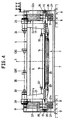
- Each rolling device shown in the drawing has - as FIG. 1 and FIG. 3 can be seen - two mirror-symmetrical to one to the plane of the drawing 2 or 4 parallel vertical center plane 2 arranged Unroll devices 1.1a. Because of the mirror symmetry of this Devices 1, 1a subsequently become those on the left in FIGS. 1 and 3, respectively Parts associated with the illustrated device 1 with a simple reference number and that of the device 1a shown in FIGS. 1 and 3 on the right assigned parts with the same reference number with the addition of a "a" denotes, without the need for a double description. As can also be seen in FIGS. 2 and 4, the two rolling devices are 1 and 1a each again largely mirror-symmetrical to a vertical running parallel to the drawing plane of FIGS.
- the rolling device has a machine frame 4, the two at a distance bearing stands 5, 5 'arranged from one another, which by means of an upper longitudinal beam 6 and lower longitudinal struts 7, 7a stiff with each other are connected.
- the stands 5, 5 ' are by means of base plates 8, 8' Ground foundations 9, 9 'supported.
- 10a, 10 ' engages as a sliding drive a swivel drive 12, 12a, as a piston-cylinder drive which can be acted upon with pressure fluid on both sides trained and stationary, but swiveling in one the respective base plate 8, 8 'attached base bearing 13, 13a is.
- Support shaft 14, 14a supported at both ends, with bearings 15, 15 'or 15a.
- These bearings 15, 15 'and 15a are designed so that the Support shafts 14, 14a can not only be moved so that their central longitudinal axes 16, 16a parallel to themselves and to the vertical median plane 2 are moved, but that they are also opposite to their longitudinal direction can be pivoted or deflected. So you can be so distracted be that their central longitudinal axes 16,16a substantially in the Horizontal moved out of a position parallel to the vertical center plane 2 become.
- the bearings 15, 15 'and 15a are, for example, as spherical bearings designed with a certain pivoting mobility and with a certain displacement in the direction of the respective Axis 16 and 16a are mounted in the bearing levers 10, 10 'and 10a.
- the Bearings 15, 15 'and 15a are located on the base bearings 11, 11a and 11 'opposite upper ends of the bearing levers 10, 10a and 10'.
- each support shaft 14, 14a there are two support arms at a distance from one another 17, 17 'and 17a attached to the support shaft 14, 14a rotatably.
- support shafts 14, 14a each point parallel to their central longitudinal axis 16, 16a extending outer guide grooves 18 into which the respective Support arms 17, 17 ', 17a engage trained projections 19, 19a, so that the support arms 17, 17a, 17 'relative to the respective support shaft 14, 14a rotatably but slidably mounted in the longitudinal direction thereof are.
- Support arms 17, 17 'and 17a are mounting pins 24, 24' attached are directed towards each other in each rolling device 1 or 1a.
- the swivel drives 12 and 12a of each rolling device 1 and 1a are can be acted upon independently, that is to say can be controlled, so that the triggered movements are independent of each other.
- the pivot arms 21, 21 ' are pivoted by means of the lifting drives 22, 22' in such a way that that the receiving pin 24, 24 'in a to the central axis 29 of the Roll 28 aligned position come. If the rolling axis 26 is not parallel to the central axis 29, ie not parallel to the vertical central plane 2, runs, then by correspondingly different control the pivot drives 12, the bearing levers 10, 10 'pivoted so that the Roll axis 26 in a position parallel to the central axis 29 of the paper roll 28 is coming.
- each rolling device 1 and 1a pivoted relative to each other can be, with appropriate pivoting the corresponding central longitudinal axis 16 or 16a of the respective support shaft 14 or 14a and thus the rolling axis 26 or 26a.
- the bearing lever 10, 10 'and 10a can different non-parallel courses of the central axis 29 of the Roll 28 are balanced relative to the median level 2, as in the for the Unrolling device 1 indicated in Fig. 1 swivel tracks 30 and 31st for the central axis of the roller 28 is shown.
- the setting drives 20 are controlled in such a way that the receiving pin 24, 24 'concentrically in the paper roll 28 intervene. Then, by appropriate control, the Swivel drives 12, 12 'an alignment of the paper roll 28 in such a way that its central axis 29 in a parallel to the central plane 2 and horizontal position, i.e. the desired starting position. Subsequently it is applied to the lifting drives 22, 22 'in a Unroll suitable position swiveled up.
- each support shaft 14, 14a in principle only one lifting drive 22 or 22a or 22 'or 22a' is necessary; it is only for each support shaft 14, 14a in the illustrated Embodiments provided two lifting drives 22, 22 'and 22a, 22a', around no significant torsions in the respective support shaft 14 or 14a let develop.
- Fig. 2 the greatest possible length a is one for the rolling device 1 paper roll 28 to be accommodated and the smallest possible length b a Paper roll 28 shown. 1 is left for the swivel path 30 with the support shaft shifted as far as possible towards the central plane 2 14 the entire pivoting range of the support arms 17, 17 'indicated while in Fig. 1 on the right for the rolling device 1a for the swivel track 31a as far as possible from the center plane 2 pivoted support shaft 14a the largest possible swivel range of the support arms 17a is shown.
- the control of the various drives that can be pressurized with fluid, thus the swivel drives 12 and 12a, the shift drives 20, 20a and the lifting drives 22, 22 ', 22a, 22a' takes place in a known manner, for example via solenoid valves, which in turn are only indicated central controller 33 are controlled.
- This central controller 33 receives signals from only indicated sensors 32, 32 ', 32a, the actual position the paper roll 28, specifically its distance from the donors and thus from the vertical center plane 2.
- the paper roll 28 donors 34 and 34a are provided, the distance the paper roll 28 from the respective upper encoder 34 or 34a and thus capture the distance 29 over the pad 27. Of these donors 34, or 34a, the diameter of the roller 28 is detected.
- the encoders 32, 32 'and 32a In contrast, with the encoders 32, 32 'and 32a, the skew of the axis 29 relative to the vertical center plane 2. Such an imbalance can, for example up to +/- 60 mm, which can be compensated. Furthermore can be activated via a suitable control of the part-turn actuators 12 or 12a uneven web tension can be compensated.
Landscapes
- Replacement Of Web Rolls (AREA)
- Spinning Or Twisting Of Yarns (AREA)
Description
Die Erfindung betrifft eine Abroll-Einrichtung nach dem Oberbegriff des
Anspruches 1.The invention relates to a rolling device according to the preamble of
Derartige Abroll-Einrichtungen sind beispielsweise aus der EP 0 629 574 B1 bekannt. Hierbei werden die Tragwellen über eine stationäre Steuerkurve derart geführt, daß die durch die Aufnahmezapfen definierte Abrollachse für die Rolle über einer ortsfesten, die Papier-Rolle auf dem Boden aufnehmenden Auflage in einer Vertikalebene bewegt wird, so daß unterschiedlich dicke Papier-Rollen, deren Mittel-Achse also entsprechend unterschiedlichen Höhen-Abstand über der Auflage hat, sicher ergriffen werden können. Bei dieser bekannten Abroll-Einrichtung muß die Papier-Rolle auf der Auflage, also gegenüber dem Boden, so ausgerichtet sein, daß die Mittel-Achse der Rolle parallel zur Abroll-Achse der Abroll-Einrichtung verläuft. Zum entsprechenden Ausrichten der Mittel-Achse einer Papier-Rolle dient beispielsweise eine Vorrichtung, wie sie in der EP 0 700 854 A2 (entspr. US-Patent 5 755 395) dargestellt und beschrieben ist.Such rolling devices are, for example, from EP 0 629 574 B1 known. Here, the support shafts over a stationary control curve guided such that the rolling axis defined by the receiving pin for the roll over a stationary, the paper roll on the floor Edition is moved in a vertical plane so that different thick paper rolls, their center axis accordingly different Height distance above the pad has to be gripped safely can. In this known roll-off device, the paper roll on the support, i.e. opposite the floor, so that the Center axis of the roll parallel to the roll axis of the roll device runs. For the corresponding alignment of the center axis of a paper roll A device such as that used in EP 0 700 854 is used, for example A2 (corresponding to U.S. Patent 5,755,395) is shown and described.
Aus der EP 0 387 365 B1 (entspr. US-Patent 4,930,713) ist eine weitere Abroll-Einrichtung bekannt, bei der die die Tragarme tragende Tragwelle über Exzenter-Kurvenscheiben geführt ist. Hierdurch ist es ebenfalls möglich, die Aufnahmezapfen der Tragarme in einer Vertikalebene zu bewegen, so dass unterschiedlich dicke Papier-Rollen sicher ergriffen werden können.Another is from EP 0 387 365 B1 (corresponding to US Pat. No. 4,930,713) Unwinding device known in which the support shaft carrying the support arms is guided over eccentric cams. This also makes it possible move the support pins of the support arms in a vertical plane, so that paper rolls of different thicknesses can be gripped safely can.
Aus der DE 42 24 309 A1 ist eine Spannvorrichtung für Spulen oder Wickelkerne für Bandmaterial bekannt, die paarweise einander zugeordnete Spulen-Tragarme aufweist, die einerseits in horizontal in ihrem Abstand zueinander veränderbaren Haltern schwenkbar gelagert sind und die an ihren freien Enden Aufnahmezapfen zur Aufnahme einer Spule aufweisen. Die Tragarme sind mittels vertikaler Antriebe derartig schwenkbar, dass ihre Aufnahmezapfen im Wesentlichen vertikal verstellt werden. Die Spulen-Tragarme sind weiter in ihrem Abstand zueinander verstellbar und insgesamt horizontal quer zu ihrer Abroll-Achse verschiebbar. Sie weisen weiterhin eine Dezentriereinrichtung auf, mittels derer die Aufnahmezapfen für eine Spule gleichzeitig und entgegengesetzt aus ihrer koaxial fluchtenden Position verschoben werden können. Zur Funktion ist insgesamt nur angegeben, dass den Tragarmen eine größere Bewegungsfreiheit und umfassendere Verstellmöglichkeiten für gegenseitiges Annähern oder Entfernen verliehen sei, wodurch auch ein vergrößerter Arbeitsbereich in Bezug auf die Breite der Spulen oder Wickelrollen entstehe.DE 42 24 309 A1 describes a tensioning device for coils or winding cores known for tape material that paired with each other Has coil support arms, the one hand in horizontal in their distance mutually changeable holders are pivotally mounted and on their free ends have receiving pins for receiving a coil. The support arms can be pivoted by means of vertical drives in such a way that their The mounting spigot can be adjusted essentially vertically. The coil support arms are further adjustable in their distance from each other and overall can be moved horizontally across its roll axis. They continue to point a decentering device, by means of which the receiving pins for a coil at the same time and opposite from its coaxially aligned Position can be moved. To function is overall only indicated that the support arms have greater freedom of movement and more extensive Adjustment options for mutual approaching or removing is awarded, which also means an enlarged work area in relation to the width of the spools or winding rolls.
Aus der DE G 86 29 994 U ist weiterhin eine Abroll-Einrichtung bekannt, bei der die die Tragarme tragende Tragwelle in einem Parallel-Lenk-System gelagert ist, so dass die Aufnahmezapfen zwangsweise in einer Vertikalebene geführt werden.A rolling device is also known from DE G 86 29 994 U, in which the support shaft carrying the support arms in a parallel steering system is mounted so that the locating pin is forcibly in one Be guided in the vertical plane.
Der Erfindung liegt die Aufgabe zugrunde, eine Abroll-Einrichtung der gattungsgemäßen Art so auszugestalten, dass ein Ausrichten der aufzunehmenden Rolle vor der Aufnahme durch die Abroll-Einrichtung nicht notwendig ist. The invention has for its object a rolling device Generic type so that an alignment of the to be recorded Do not roll before being picked up by the roll-off device necessary is.
Diese Aufgabe wird erfindungsgemäß durch die Merkmale im Kennzeichnungsteil
des Anspruches 1 gelöst. Dadurch, dass die Tragwelle und damit
die Abroll-Achse nicht nur parallel zu sich selbst, sondern auch gegenüber
sich selbst in der Horizontalen um einige Grad verschwenkbar ist, wozu die
Verschiebeantriebe der Lagerträger unabhängig voneinander ansteuerbar
sind, dass also die Lagerträger einer Abroll-Vorrichtung relativ zueinander
bewegbar sind, können die Aufnahmezapfen einer Abroll-Vorrichtung in
eine Position gebracht werden, in der die durch sie definierte Abroll-Achse
mit der Mittel-Achse der vor der Einrichtung liegenden Papier-Rolle fluchtet.This object is achieved by the features in the labeling part
of
Die Unteransprüche geben vorteilhafte Ausgestaltungen wieder. The subclaims represent advantageous refinements.
Weitere Merkmale, Vorteile und Einzelheiten der Erfindung ergeben sich aus der nachfolgenden Beschreibung zweier Ausführungsbeispiele anhand der Zeichnung. Es zeigt:
- Fig. 1
- eine teilweise aufgebrochene Seitenansicht einer Abroll-Einrichtung entsprechend dem Sichtpfeil in Fig. 2,
- Fig. 2
- eine Längsansicht der Abroll-Einrichtung gemäß dem Sichtpfeil II in Fig. 1,
- Fig. 3
- eine Seitenansicht einer abgewandelten Ausführungsform einer Abroll-Einrichtung entsprechend dem Sichtpfeil m in Fig. 4 und
- Fig. 4
- eine Längsansicht der abgewandelten Ausführungsform einer Abroll-Einrichtung gemäß dem Sichtpfeil IV in Fig. 3.
- Fig. 1
- 3 shows a partially broken side view of a roll-off device according to the arrow in FIG. 2,
- Fig. 2
- 2 shows a longitudinal view of the rolling device according to the arrow II in FIG. 1,
- Fig. 3
- a side view of a modified embodiment of a rolling device according to the arrow m in Fig. 4 and
- Fig. 4
- 3 shows a longitudinal view of the modified embodiment of a rolling device according to the arrow IV in FIG. 3.
Die in den Figuren 1 bis 4 dargestellten Ausführungsformen einer Abroll-Einrichtung stimmen weitgehend überein. Die nachfolgende Beschreibung gilt daher für beide Ausführungsformen, soweit nicht ausdrücklich auf Unterschiede hingewiesen wird. Teile, die ganz wesentlich in den beiden Ausführungsformen übereinstimmen und sich nur durch geringfügige, für die Erfindung nicht relevante konstruktive Einzelheiten unterscheiden, werden trotzdem mit denselben Bezugsziffern versehen.The embodiments of a rolling device shown in Figures 1 to 4 largely agree. The following description therefore applies to both embodiments, unless expressly to differences is pointed out. Parts that are quite essential in the two embodiments match and differ only by minor, for which Distinguish design details not relevant to the invention nevertheless provided with the same reference numbers.
Jede in der Zeichnung dargestellte Abroll-Einrichtung weist - wie Fig. 1
und Fig. 3 entnehmbar ist - zwei spiegelsymmetrisch zu einer zur Zeichnungsebene
nach Fig. 2 bzw. 4 parallelen vertikalen Mittel-Ebene 2 angeordnete
Abroll-Vorrichtungen 1,1a auf. Wegen der Spiegelsymmetrie dieser
Vorrichtungen 1, 1a werden nachfolgend die der in Fig. 1 bzw. 3 links
dargestellten Vorrichtung 1 zugeordneten Teile mit einer einfachen Bezugsziffer
und die der in Fig. 1 bzw. 3 rechts dargestellten Vorrichtung 1a
zugeordneten Teile mit derselben Bezugsziffer unter Hinzufügung eines
"a" bezeichnet, ohne daß es jeweils einer doppelten Beschreibung bedarf.
Wie weiterhin Fig. 2 bzw. 4 entnehmbar ist, sind die beiden Abroll-Vorrichtungen
1 und 1a jeweils selber wieder weitgehend spiegelsymmetrisch
zu einer parallel zur Zeichnungsebene der Fig. 1 bzw. 3 verlaufenden vertikalen
Mittelebene 3 aufgebaut. Aus diesem Grunde werden die in Fig. 2
bzw. 4 rechts dargestellten, ebenfalls in Fig. 1 bzw. 3 sichtbaren Teile mit
Bezugsziffern ohne einen hochgesetzten Strich bezeichnet, während die in
Fig. 2 bzw. 4 links dargestellten Teile mit derselben Bezugsziffer, aber zusätzlich
einem hochgesetzten Strich bezeichnet werden, ohne daß es insoweit
jeweils einer gesonderten Beschreibung bedürfte.Each rolling device shown in the drawing has - as FIG. 1
and FIG. 3 can be seen - two mirror-symmetrical to one to the plane of the
Die Abroll-Einrichtung weist ein Maschinengestell 4 auf, das zwei im Abstand
voneinander angeordnete Lager-Ständer 5, 5' aufweist, die mittels
eines oberen Längsbalkens 6 und unterer Längsstreben 7, 7a steif miteinander
verbunden sind. Die Ständer 5, 5' sind mittels Bodenplatten 8, 8' auf
Bodenfundamenten 9, 9' abgestützt.The rolling device has a machine frame 4, the two at a distance
bearing stands 5, 5 'arranged from one another, which by means of
an upper
Bei der Ausführungsform nach den Fig. und 2 ist auf jeder Bodenplatte 8,
8' für jede Abroll-Vorrichtung 1, 1a als Lagerträger ein Lager-Hebel 10,
10a bzw. 10' in einem an der jeweiligen Bodenplatte 8, 8' angeordneten
ortsfesten Basislager 11, 11a, 11' schwenkbar gelagert. An dem jeweiligen
Lagerhebel 10, 10a, 10' greift als Verschiebeantrieb ein Schwenkantrieb
12, 12a an, der als mit Druckfluid doppelseitig beaufschlagbarer Kolben-Zylinder-Antrieb
ausgebildet und ortsfest, aber verschwenkbar in einem an
der jeweiligen Bodenplatte 8, 8' angebrachten Bodenlager 13,13a angelenkt
ist.In the embodiment according to FIGS. 2 and 2, on each
In den Lagerhebeln 10, 10' der Abroll-Vorrichtung 1 und entsprechend
auch in den Lagerhebeln 10a der anderen Abroll-Vorrichtung 1a ist eine
Tragwelle 14, 14a an ihren beiden Enden gelagert und zwar mit Lagern 15,
15' bzw. 15a. Diese Lager 15, 15' bzw. 15a sind so ausgebildet, daß die
Tragwellen 14, 14a nicht nur so bewegt werden können, daß ihre Mittel-Längs-Achsen
16, 16a parallel zu sich selbst und zur vertikalen Mittelebene
2 verschoben werden, sondern daß sie auch gegenüber ihrer Längsrichtung
verschwenkt bzw. ausgelenkt werden können. Sie können also so ausgelenkt
werden, daß ihre Mittel-Längs-Achsen 16,16a im wesentlichen in der
Horizontalen aus einer Lage parallel zur vertikalen Mittelebene 2 herausbewegt
werden. Hierzu sind die Lager 15, 15' bzw. 15a beispielsweise als
sphärische Lager ausgebildet, die mit einer gewissen Schwenk-Beweglichkeit
und mit einer gewissen Verschiebbarkeit in Richtung der jeweiligen
Achse 16 bzw. 16a in den Lagerhebeln 10, 10' bzw. 10a gelagert sind. Die
Lager 15, 15' bzw. 15a befinden sich an den den Basislagern 11, 11a bzw.
11' entgegengesetzten oberen Enden der Lagerhebel 10, 10a bzw. 10'.In the bearing levers 10, 10 'of the
Auf jeder Tragwelle 14, 14a sind im Abstand voneinander zwei Tragarme
17, 17' bzw. 17a gegenüber der Tragwelle 14, 14a drehfest angebracht. Die
Tragwellen 14, 14a weisen hierzu jeweils parallel zu ihrer Mittel-Längs-Achse
16, 16a verlaufende äußere Führungsnuten 18 auf, in die am jeweiligen
Tragarm 17, 17', 17a ausgebildete Führungsvorsprünge 19, 19a eingreifen,
so daß die Tragarme 17, 17a, 17' relativ zur jeweiligen Tragwelle
14, 14a drehfest aber in deren Längsrichtung verschiebbar auf dieser gelagert
sind. Die paarweise Längsverschiebung bzw. Längseinstellung der auf
einer Tragwelle 14 bzw. 14a angeordneten Tragarme 17, 17' bzw. 17a andererseits
zueinander erfolgt mittels zweier Einstellantriebe 20, 20', bei
denen es sich ebenfalls um mit Druckfluid beaufschlagte Kolben-Zylinder-Antriebe
handelt, deren eines Ende am Tragarm 17 bzw. 17' und deren anderes
Ende jeweils an der Tragwelle 14 bzw. 14' angelenkt ist, wie insbesondere
Fig. 2 bzw. 4 entnehmbar ist.On each
Im Bereich der jeweiligen Enden der Tragwellen 14, 14a also benachbart
zu den Lagern 15, 15a bzw. 15' sind an den Tragwellen 14, 14a Schwenkarme
21, 21a bzw. 21', 21'a angebracht. An den freien Enden dieser
Schwenkarme 21, 21a bzw. 21', 21'a greifen Hubantriebe 22, 22a bzw. 22',
22'a an, bei denen es sich ebenfalls um mit Druckfluid doppelseitig beaufschlagbare
Kolben-Zylinder-Antriebe handelt, die einerseits im oberen Bereich
der Lager-Ständer 5, 5' und andererseits an den einander zugewandten
freien Enden der Schwenkarme 21, 21a bzw. 21', 21'a angelenkt sind,
wie den Fig. 1 bis 4 entnehmbar ist.In the area of the respective ends of the
An den der jeweiligen Tragwelle 14, 14a abgewandten freien Enden der
Tragarme 17, 17' bzw. 17a sind Aufnahmezapfen 24, 24' angebracht, die
bei jeder Abroll-Vorrichtung 1 bzw. 1a aufeinanderzu gerichtet sind. Diese
Aufnahmezapfen 24, 24' sind mittels am jeweiligen Tragarm 17, 17' bzw.
17a angebrachter, auch als Bremsen betreibbarer Abroll-Antriebe 25, 25',
25a antreibbar bzw. bremsbar. Die ein Paar von Aufnahmezapfen 24, 24'
verbindenden Abroll-Achsen 26 bzw. 26a sind aufgrund der geschilderten
Verschwenkbarkeit der Achsen 16, 16a ebenfalls nicht nur parallel zu sich
selbst verschiebbar, sondern auch aus ihrer Lage heraus auslenkbar.At the free ends of the
Die Schwenkantriebe 12 bzw. 12a jeder Abroll-Vorrichtung 1 bzw. 1a sind
unabhängig voneinander beaufschlagbar, also ansteuerbar, so daß die durch
sie ausgelösten Bewegungen unabhängig voneinander sind.The swivel drives 12 and 12a of each
Nachfolgend wird die Wirkungsweise der Abroll-Einrichtung beschrieben.
Ausgegangen wird davon, daß auf einer Auflage 27 eine gestrichelt angedeutete
Papier-Rolle 28 abgelegt ist, die mittels der Abroll-Vorrich-tung 1
aufgenommen, zentriert und zum Abrollen hochgeschwenkt werden soll.The mode of operation of the rolling device is described below.
It is assumed that on an edition 27 a dashed
Mittels der Hubantriebe 22, 22' werden die Schwenkarme 21, 21' so verschwenkt,
daß die Aufnahmezapfen 24, 24' in eine zur Mittel-Achse 29 der
Rolle 28 fluchtende Lage kommen. Wenn die Abroll-Achse 26 nicht parallel
zur Mittel-Achse 29, also nicht parallel zur vertikalen Mittelebene 2,
verläuft, dann werden durch entsprechend unterschiedliche Ansteuerung
der Schwenkantriebe 12 die Lagerhebel 10, 10' so verschwenkt, daß die
Abrollachse 26 in eine Lage parallel zur Mittel-Achse 29 der Papier-Rolle
28 kommt. In Fig. 1 ist angedeutet, in welchem Maße die Lagerhebel 10,
10' bzw. 10a jeder Abroll-Vorrichtung 1 bzw. 1a relativ zueinander verschwenkt
werden können, und zwar unter entsprechender Verschwenkung
der entsprechenden Mittel-Längs-Achse 16 bzw. 16a der jeweiligen Tragwelle
14 bzw. 14a und damit der Abrollachse 26 bzw. 26a. Durch gleichzeitige
gegensinnige Verschwenkung der Lagerhebel 10, 10' bzw. 10a
können unterschiedliche nichtparallele Verläufe der Mittel-Achse 29 der
Rolle 28 relativ zur Mittelebene 2 ausgeglichen werden, wie in den für die
Abroll-Vorrichtung 1 in Fig. 1 angedeuteten Schwenkbahnen 30 bzw. 31
für die Mittel-Achse der Rolle 28 dargestellt ist. Wenn die durch die Aufnahmezapfen
24 bzw. 24' definierte Abrollachse 26 mit der Mittel-Achse
29 der Rolle 28 fluchtet, dann werden die Einstellantriebe 20 derart angesteuert,
daß die Aufnahmezapfen 24, 24' konzentrisch in die Papier-Rolle
28 eingreifen. Anschließend erfolgt durch entsprechende Ansteuerung der
Schwenkantriebe 12, 12' ein Ausrichten der Papier-Rolle 28 in der Weise,
daß ihre Mittel-Achse 29 in eine parallel zur Mittelebene 2 verlaufende und
horizontale Lage, also die gewünschte Ausgangslage, kommt. Anschließend
wird sie durch Beaufschlagung der Hubantriebe 22, 22' in eine zum
Abrollen geeignete Stellung hochgeschwenkt. Für jede Tragwelle 14, 14a
ist im Grundsatz nur ein Hubantrieb 22 bzw. 22a oder 22' bzw. 22a' notwendig;
es sind lediglich für jede Tragwelle 14, 14a in den dargestellten
Ausführungsformen zwei Hubantriebe 22, 22' bzw. 22a, 22a' vorgesehen,
um in der jeweiligen Tragwelle 14 bzw. 14a keine nennenswerten Torsionen
entstehen zu lassen.The
In Fig. 2 ist für die Abroll-Vorrichtung 1 die größtmögliche Länge a einer
aufzunehmenden Papier-Rolle 28 und die kleinstmögliche Länge b einer
Papier-Rolle 28 dargestellt. Weiterhin ist in Fig. 1 links für die Schwenkbahn
30 mit weitestmöglich zur Mittelebene 2 hin verschobener Tragwelle
14 der gesamte Schwenkbereich der Tragarme 17, 17' angedeutet, während
in Fig. 1 rechts für die Abrollvorrichtung 1a für die Schwenkbahn 31a bei
weitestmöglich von der Mittelebene 2 weggeschwenkter Tragwelle 14a der
hierbei größtmögliche Schwenkbereich der Tragarme 17a dargestellt ist.
Die Ansteuerung der verschiedenen mit Druckfluid beaufschlagbaren Antriebe,
also der Schwenkantriebe 12 und 12a, der Verschiebeantriebe 20,
20a und der Hubantriebe 22, 22', 22a, 22a' erfolgt in bekannter Weise, beispielsweise
über Magnetventile, die wiederum von einer nur angedeuteten
zentralen Steuerung 33 angesteuert werden. Diese zentrale Steuerung 33
erhält von nur angedeuteten Gebern 32, 32', 32a Signale, die die Ist-Stellung
der Papier-Rolle 28, und zwar konkret deren Abstand von den Gebern
und damit von der vertikalen Mittelebene 2, erfassen. Weiterhin sind
oberhalb der Papier-Rolle 28 Geber 34 bzw. 34a vorgesehen, die den Abstand
der Papier-Rolle 28 vom jeweiligen oberen Geber 34 bzw. 34a und
damit den Abstand 29 über der Auflage 27 erfassen. Von diesen Gebern 34,
bzw. 34a wird also der Durchmesser der Rolle 28 erfaßt. Demgegenüber
wird mit den Gebern 32, 32' bzw. 32a die Schieflage der Achse 29 relativ
zur vertikalen Mittelebene 2 erfaßt. Eine solche Schieflage kann beispielsweise
bis zu +/- 60 mm betragen, die ausgeglichen werden können. Im übrigen
können über eine entsprechende Ansteuerung der Schwenkantriebe
12 bzw. 12a ungleichmäßige Bahnspannungen ausgeglichen werden.In Fig. 2, the greatest possible length a is one for the rolling
Bei der Ausführungsform nach den Figuren 3 und 4 sind die Tragwellen
14, 14a mittels der Lager 15, 15', 15a in horizontal und quer zur vertikalen
Mittelebene 2 verschiebbaren Lagerträgern 35, 35', 35a gelagert, die wiederum
in Schienen 36, 36', 36a verschiebbar geführt sind, die an den Lager-Ständern
5, 5' angebracht sind. Da bei dieser Ausgestaltung die Lagerträger
35, 35', 35a ausschließlich horizontale Bewegungen ausführen, greifen
die Verschiebeantriebe 37, 37a ebenfalls horizontal an, sind also einerseits
an den Lagerträgern 35, 35a und andererseits in etwa gleicher Höhe
am Lager-Ständer 5 angelenkt. Auch für diese Ausführungsform ist in Fig.
3 die weitestmöglich nach innen eingezogene und die weitestmöglich nach
außen ausgeschobene Stellung des jeweiligen Lagerträgers 35 bzw. 35a
dargestellt, woraus sich auch die horizontale Verschwenkbarkeit der Abroll-Achse
26 bzw. 26a ergibt.In the embodiment according to Figures 3 and 4 are the
Claims (7)
- An unroll device for paper reels (28) with at least one unroll stand (1, 1a), comprisingcharacterized in that the supporting shaft (14, 14a) is run on the bearing supports (10, 10', 10a; 35, 35', 35a) such that its central longitudinal axis (16, 16a) is not only displaceable parallel to itself, but is also pivotal about a base position substantially in a horizontal plane; anda machine frame (4), which has two bearing stands (5, 5') spaced apart;bearing supports (10, 10', 10a; 35, 35', 35a), which are guided substantially horizontally movably on the bearing stands (5, 5');shifting drives (12, 12a; 37, 37a) acting on the bearing supports (10, 10', 10a; 35, 35', 35a);a supporting shaft (14, 14a), the ends of which are run on the bearing supports (10, 10', 10a; 35, 35', 35a);lugs (17, 17', 17a), which are guided on the supporting shaft (14, 14a) non-rotatably relative thereto, but displaceably in their longitudinal direction;centering pivots (24, 24', 24a) for holding a reel (28), which are mounted on the lugs (17, 17', 17a) and define an unrolling axis (26, 26a); andat least one lifting drive (22, 22', 22a, 22'a) coupled to the supporting shaft (14, 14a);
in that the shifting drives (12, 12'; 37, 37') can be operated individually. - An unroll device according to claim 1, characterized in that the supporting shaft (14, 14a) is run on the bearing supports (10, 10', 10a; 35, 35', 35a) by means of spherical bearings (15, 15', 15a).
- An unroll device according to claim 1 or 2, characterized in that clearance in the direction of the central longitudinal axis (16, 16a) exists between the supporting shaft (14, 14a) and the bearing supports (10, 10', 10a; 35, 35', 35a).
- An unroll device according to one of claims 1 to 3, characterized in that the bearing supports are bearing levers (10, 10', 10a) pivotally articulated to the bearing stands (5, 5').
- An unroll device according to one of claims 1 to 3, characterized in that the bearing supports (35, 35', 35a) are formed substantially horizontally displaceably on the bearing stand (5, 5').
- An unroll device according to one of claims 1 to 5, characterized in that at least one transmitter (34, 34a) is provided for detecting the distance of a central longitudinal axis (29) of the reel (28) from the transmitter (34, 34a).
- An unroll device according to one of claims 1 to 6, characterized in that transmitters (32, 32', 32a) are provided for detecting an oblique position of the reel (28).
Applications Claiming Priority (2)
| Application Number | Priority Date | Filing Date | Title |
|---|---|---|---|
| DE19824695A DE19824695A1 (en) | 1998-06-03 | 1998-06-03 | Paper roll holder for manufacture of corrugated paper allows holder lever |
| DE19824695 | 1998-06-03 |
Publications (3)
| Publication Number | Publication Date |
|---|---|
| EP0968945A2 EP0968945A2 (en) | 2000-01-05 |
| EP0968945A3 EP0968945A3 (en) | 2000-08-23 |
| EP0968945B1 true EP0968945B1 (en) | 2003-07-30 |
Family
ID=7869712
Family Applications (1)
| Application Number | Title | Priority Date | Filing Date |
|---|---|---|---|
| EP99109912A Expired - Lifetime EP0968945B1 (en) | 1998-06-03 | 1999-05-20 | Unwinding device |
Country Status (4)
| Country | Link |
|---|---|
| US (1) | US6267320B1 (en) |
| EP (1) | EP0968945B1 (en) |
| JP (1) | JPH11349194A (en) |
| DE (2) | DE19824695A1 (en) |
Families Citing this family (6)
| Publication number | Priority date | Publication date | Assignee | Title |
|---|---|---|---|---|
| GB2353023B (en) * | 1999-08-07 | 2001-07-04 | Walter Stephen Weston | Shaftless reel stand |
| US6484964B1 (en) * | 2000-08-17 | 2002-11-26 | Elco Enterprises, Inc. | Welding wire dereeler |
| FI125210B (en) * | 2011-03-08 | 2015-07-15 | Valmet Technologies Inc | Arrangement for handling loads |
| CN104925554B (en) * | 2014-01-23 | 2018-02-02 | 弗斯伯股份公司 | For unwinding the unwinding equipment of sheet material volume |
| CN107310957B (en) * | 2017-08-16 | 2019-02-22 | 南京安顺自动化装备有限公司 | Station type rolling slitter arm forced locking device |
| FR3089509B1 (en) * | 2018-12-11 | 2021-01-01 | Additif | Lifting device |
Family Cites Families (13)
| Publication number | Priority date | Publication date | Assignee | Title |
|---|---|---|---|---|
| US1869545A (en) * | 1929-04-22 | 1932-08-02 | Goss Printing Press Co Ltd | Web roll supporting mechanism |
| US3175779A (en) * | 1962-12-19 | 1965-03-30 | Samuel M Langston Co | Roll lift shaft mounting |
| IT1116309B (en) * | 1977-06-02 | 1986-02-10 | Bugnone Aldo | TAPE WRAPPING AND UNWINDING DEVICE FOR PRINTING MACHINES, PAINTING MACHINES, COUPLING MACHINES OR SIMILAR |
| JPS57184045A (en) * | 1981-05-09 | 1982-11-12 | Mitsubishi Heavy Ind Ltd | Mill roll stand |
| GB2106875B (en) * | 1981-10-05 | 1985-06-26 | Rengo Co Ltd | Automatically mounting a web roll on a mill roll stand |
| DE8629994U1 (en) | 1986-11-08 | 1987-10-01 | Peters Maschinenfabrik Gmbh, 2000 Hamburg, De | |
| DE3715475A1 (en) * | 1987-05-08 | 1988-12-22 | Jagenberg Ag | DEVICE FOR UNWINDING A MATERIAL COIL FROM A ROLL |
| US4930713A (en) * | 1989-03-10 | 1990-06-05 | Mitsubishi Jukogyo Kabushiki Kaisha | Mill roll stand |
| DE4008897A1 (en) * | 1990-03-20 | 1991-09-26 | Peter Maier | Sliding ring bearing for winding rod spigots - has shaft with recess closable by movable side ring |
| FR2693711A1 (en) * | 1992-07-25 | 1994-01-21 | Ozcariz Basterra Laureano | Machine for fixing bobbins. |
| US5320296A (en) * | 1992-07-30 | 1994-06-14 | Laureano Ozcariz | Roll handling machine |
| DE4318632A1 (en) * | 1993-06-04 | 1994-12-08 | Bielomatik Leuze & Co | Loading device for material rolls, in particular for paper rolls |
| DE9414677U1 (en) * | 1994-09-09 | 1994-12-15 | Bhs Corr Masch & Anlagenbau | Paper roll transport and alignment device for a paper processing unwinding device |
-
1998
- 1998-06-03 DE DE19824695A patent/DE19824695A1/en not_active Withdrawn
-
1999
- 1999-05-20 DE DE59906418T patent/DE59906418D1/en not_active Expired - Lifetime
- 1999-05-20 EP EP99109912A patent/EP0968945B1/en not_active Expired - Lifetime
- 1999-06-02 US US09/323,956 patent/US6267320B1/en not_active Expired - Lifetime
- 1999-06-02 JP JP11155468A patent/JPH11349194A/en active Pending
Also Published As
| Publication number | Publication date |
|---|---|
| EP0968945A2 (en) | 2000-01-05 |
| EP0968945A3 (en) | 2000-08-23 |
| JPH11349194A (en) | 1999-12-21 |
| US6267320B1 (en) | 2001-07-31 |
| DE19824695A1 (en) | 1999-12-09 |
| DE59906418D1 (en) | 2003-09-04 |
Similar Documents
| Publication | Publication Date | Title |
|---|---|---|
| DE3007362C2 (en) | Flat tire testing machine | |
| DE102005032600B4 (en) | Device for aligning a roll of material in front of the uprights in a reel changer | |
| DE2651304C2 (en) | Paver finisher | |
| DE4007329C2 (en) | ||
| EP0464505B1 (en) | Longitudinal folding device | |
| EP0909253B1 (en) | Unwinder device for reels | |
| DE1635428B2 (en) | UNWINDING DEVICE, IN PARTICULAR. FOR FABRIC WEB IN FABRIC MAKING MACHINES | |
| EP0968945B1 (en) | Unwinding device | |
| DE2428113C2 (en) | Device for unilaterally straight-edged winding of material webs | |
| DE102013015326A1 (en) | Kantenausrollvorrichtung | |
| EP2296887A1 (en) | System for gripping a cylinder conducting ink in a printing press | |
| DE2122204A1 (en) | Weight compensation device for the tool support guided along a crossbeam of a machine tool | |
| DE1560012C3 (en) | Device for laying out webs of fabric | |
| DD219809A5 (en) | TRACKING MACHINE, THE CHASSIS OF WHICH IS EQUIPPED WITH A DEVICE FOR LIFTING AND ALIGNING A TRACK | |
| DE19821603A1 (en) | Longitudinal folding device on the folder of rotary printing machines | |
| EP0232553A1 (en) | Winding device for a continuously arriving imbricated batch of flexible flat products | |
| WO2013056758A1 (en) | Two-drum winder | |
| DE1295305B (en) | Movable support device for electrical and pneumatic supply lines | |
| DE19746734C2 (en) | Messerfaltvorrichtung | |
| DE102008015670A1 (en) | Method for rolling up a web roll and reel-up for a web | |
| EP0629574A1 (en) | Loading device for material, in particular for paper rolls | |
| AT511463B1 (en) | BAND TREATMENT DEVICE | |
| DE4107585A1 (en) | TEST TEST FOR VEHICLE TIRES | |
| EP1477443B1 (en) | Roll changer | |
| DE3806188C1 (en) | Plough folding device for the longitudinal folding of a web of material |
Legal Events
| Date | Code | Title | Description |
|---|---|---|---|
| PUAI | Public reference made under article 153(3) epc to a published international application that has entered the european phase |
Free format text: ORIGINAL CODE: 0009012 |
|
| AK | Designated contracting states |
Kind code of ref document: A2 Designated state(s): DE FR GB IT |
|
| AX | Request for extension of the european patent |
Free format text: AL;LT;LV;MK;RO;SI |
|
| PUAL | Search report despatched |
Free format text: ORIGINAL CODE: 0009013 |
|
| AK | Designated contracting states |
Kind code of ref document: A3 Designated state(s): AT BE CH CY DE DK ES FI FR GB GR IE IT LI LU MC NL PT SE |
|
| AX | Request for extension of the european patent |
Free format text: AL;LT;LV;MK;RO;SI |
|
| RIC1 | Information provided on ipc code assigned before grant |
Free format text: 7B 65H 19/12 A, 7B 65H 16/06 B |
|
| 17P | Request for examination filed |
Effective date: 20000923 |
|
| AKX | Designation fees paid |
Free format text: DE FR GB IT |
|
| 17Q | First examination report despatched |
Effective date: 20020716 |
|
| GRAH | Despatch of communication of intention to grant a patent |
Free format text: ORIGINAL CODE: EPIDOS IGRA |
|
| GRAH | Despatch of communication of intention to grant a patent |
Free format text: ORIGINAL CODE: EPIDOS IGRA |
|
| GRAA | (expected) grant |
Free format text: ORIGINAL CODE: 0009210 |
|
| AK | Designated contracting states |
Designated state(s): DE FR GB IT |
|
| REG | Reference to a national code |
Ref country code: GB Ref legal event code: FG4D Free format text: NOT ENGLISH |
|
| GBT | Gb: translation of ep patent filed (gb section 77(6)(a)/1977) |
Effective date: 20030730 |
|
| REF | Corresponds to: |
Ref document number: 59906418 Country of ref document: DE Date of ref document: 20030904 Kind code of ref document: P |
|
| ET | Fr: translation filed | ||
| PLBE | No opposition filed within time limit |
Free format text: ORIGINAL CODE: 0009261 |
|
| STAA | Information on the status of an ep patent application or granted ep patent |
Free format text: STATUS: NO OPPOSITION FILED WITHIN TIME LIMIT |
|
| 26N | No opposition filed |
Effective date: 20040504 |
|
| PGFP | Annual fee paid to national office [announced via postgrant information from national office to epo] |
Ref country code: GB Payment date: 20090528 Year of fee payment: 11 |
|
| GBPC | Gb: european patent ceased through non-payment of renewal fee |
Effective date: 20100520 |
|
| PG25 | Lapsed in a contracting state [announced via postgrant information from national office to epo] |
Ref country code: GB Free format text: LAPSE BECAUSE OF NON-PAYMENT OF DUE FEES Effective date: 20100520 |
|
| PGFP | Annual fee paid to national office [announced via postgrant information from national office to epo] |
Ref country code: FR Payment date: 20140516 Year of fee payment: 16 |
|
| PGFP | Annual fee paid to national office [announced via postgrant information from national office to epo] |
Ref country code: IT Payment date: 20150519 Year of fee payment: 17 |
|
| REG | Reference to a national code |
Ref country code: FR Ref legal event code: ST Effective date: 20160129 |
|
| PG25 | Lapsed in a contracting state [announced via postgrant information from national office to epo] |
Ref country code: FR Free format text: LAPSE BECAUSE OF NON-PAYMENT OF DUE FEES Effective date: 20150601 |
|
| PGFP | Annual fee paid to national office [announced via postgrant information from national office to epo] |
Ref country code: DE Payment date: 20160725 Year of fee payment: 18 |
|
| PG25 | Lapsed in a contracting state [announced via postgrant information from national office to epo] |
Ref country code: IT Free format text: LAPSE BECAUSE OF NON-PAYMENT OF DUE FEES Effective date: 20160520 |
|
| REG | Reference to a national code |
Ref country code: DE Ref legal event code: R119 Ref document number: 59906418 Country of ref document: DE |
|
| PG25 | Lapsed in a contracting state [announced via postgrant information from national office to epo] |
Ref country code: DE Free format text: LAPSE BECAUSE OF NON-PAYMENT OF DUE FEES Effective date: 20171201 |