EP0968452B1 - Optisches schaltelement und schaltanordnung - Google Patents
Optisches schaltelement und schaltanordnung Download PDFInfo
- Publication number
- EP0968452B1 EP0968452B1 EP98917009A EP98917009A EP0968452B1 EP 0968452 B1 EP0968452 B1 EP 0968452B1 EP 98917009 A EP98917009 A EP 98917009A EP 98917009 A EP98917009 A EP 98917009A EP 0968452 B1 EP0968452 B1 EP 0968452B1
- Authority
- EP
- European Patent Office
- Prior art keywords
- switching element
- recess
- optical
- light
- movable body
- Prior art date
- Legal status (The legal status is an assumption and is not a legal conclusion. Google has not performed a legal analysis and makes no representation as to the accuracy of the status listed.)
- Expired - Lifetime
Links
Images





Classifications
-
- G—PHYSICS
- G02—OPTICS
- G02B—OPTICAL ELEMENTS, SYSTEMS OR APPARATUS
- G02B26/00—Optical devices or arrangements for the control of light using movable or deformable optical elements
- G02B26/004—Optical devices or arrangements for the control of light using movable or deformable optical elements based on a displacement or a deformation of a fluid
-
- G—PHYSICS
- G02—OPTICS
- G02B—OPTICAL ELEMENTS, SYSTEMS OR APPARATUS
- G02B6/00—Light guides; Structural details of arrangements comprising light guides and other optical elements, e.g. couplings
- G02B6/24—Coupling light guides
- G02B6/26—Optical coupling means
- G02B6/35—Optical coupling means having switching means
- G02B6/3538—Optical coupling means having switching means based on displacement or deformation of a liquid
-
- G—PHYSICS
- G02—OPTICS
- G02B—OPTICAL ELEMENTS, SYSTEMS OR APPARATUS
- G02B6/00—Light guides; Structural details of arrangements comprising light guides and other optical elements, e.g. couplings
- G02B6/24—Coupling light guides
- G02B6/26—Optical coupling means
- G02B6/35—Optical coupling means having switching means
- G02B6/351—Optical coupling means having switching means involving stationary waveguides with moving interposed optical elements
- G02B6/3522—Optical coupling means having switching means involving stationary waveguides with moving interposed optical elements the optical element enabling or impairing total internal reflection
-
- G—PHYSICS
- G02—OPTICS
- G02B—OPTICAL ELEMENTS, SYSTEMS OR APPARATUS
- G02B6/00—Light guides; Structural details of arrangements comprising light guides and other optical elements, e.g. couplings
- G02B6/24—Coupling light guides
- G02B6/26—Optical coupling means
- G02B6/35—Optical coupling means having switching means
- G02B6/354—Switching arrangements, i.e. number of input/output ports and interconnection types
- G02B6/3544—2D constellations, i.e. with switching elements and switched beams located in a plane
- G02B6/3546—NxM switch, i.e. a regular array of switches elements of matrix type constellation
-
- G—PHYSICS
- G02—OPTICS
- G02B—OPTICAL ELEMENTS, SYSTEMS OR APPARATUS
- G02B6/00—Light guides; Structural details of arrangements comprising light guides and other optical elements, e.g. couplings
- G02B6/24—Coupling light guides
- G02B6/26—Optical coupling means
- G02B6/35—Optical coupling means having switching means
- G02B6/354—Switching arrangements, i.e. number of input/output ports and interconnection types
- G02B6/3554—3D constellations, i.e. with switching elements and switched beams located in a volume
- G02B6/3556—NxM switch, i.e. regular arrays of switches elements of matrix type constellation
-
- G—PHYSICS
- G02—OPTICS
- G02B—OPTICAL ELEMENTS, SYSTEMS OR APPARATUS
- G02B6/00—Light guides; Structural details of arrangements comprising light guides and other optical elements, e.g. couplings
- G02B6/24—Coupling light guides
- G02B6/26—Optical coupling means
- G02B6/35—Optical coupling means having switching means
- G02B6/3564—Mechanical details of the actuation mechanism associated with the moving element or mounting mechanism details
- G02B6/3568—Mechanical details of the actuation mechanism associated with the moving element or mounting mechanism details characterised by the actuating force
- G02B6/3572—Magnetic force
Definitions
- the invention relates to an optical switching element.
- the invention further relates to a switching arrangement.
- a similar circuit arrangement is from the IEEE Transactions on Components, Packaging, and Manufacturing Techology - Part B, Vol. 18, No. 2, May 1995, pages 241-244.
- Matrix switches are known for connecting glass fiber lines, with which N-optical input channels arbitrarily on M-optical output channels can be switched.
- the number of glass fibers to be connected is depending on the respective area of application.
- matrix switches with a variety of inputs and Output channels use.
- micro-optical Components that are moved with high precision are also optical Known switching elements that work on a switching principle, the one Movement of micro-optical components is not necessary.
- GB 1 494 150 describes an optical switching element in one Optical fiber, at which an interface on which the incident light strikes between a state of total reflection and transmission is switched.
- the known optical switch has in the core of the Optical fiber a narrow gap.
- the gap forms a plane Interface between an optically denser medium, i.e. the material the core of the optical fiber, and an optically thinner medium, i.e. a gaseous substance in the gap so that it slants towards the interface falling light guided along the optical waveguide at the interface is totally reflected in the direction of an adjacent optical waveguide.
- a liquid whose refractive index is the refractive index corresponds to the material from which the core of the optical waveguide is made is one with a heater on the optical fiber attached storage container provided. Due to thermal expansion the liquid in the through the cladding layer in the core layer of the Optical fiber protruding slot pressed. In another Embodiment is the liquid substance in the slot by heating brought into the gas phase.
- a disadvantage is the complex production of the known switch, because in one Optical fiber must first be inserted into a slot, then a device is to be attached for filling and this structure is sealed to the outside must become. By slitting the optical fiber you can only Realize parallel surfaces that are also reflective surfaces do not have high optical quality. Furthermore, the well-known Switch has a high optical attenuation because of the fiber optic diverging light beam not emerging in the area of the slot is led. Therefore, a part can in the transmitting switching state couple adjacent optical fibers, resulting in a high Crosstalk of the known switch leads.
- the invention has for its object to provide an optical switching element low optical attenuation and low crosstalk create, which has a compact structure and a long life and can be produced inexpensively.
- the invention lies the task is based on a switching arrangement with N-optical inputs and M-optical outputs with the above characteristics To make available.
- Switching arrangements with switching elements arranged in matrix form are from an article by M. Makihara et al. in Proceedings of the Electronic Components and Technology Conference, May 1995, pages 418-422.
- the switching elements described there consist of a translucent Base body with recesses that are partially filled with a liquid. By Immersing a movable body in these recesses becomes a gap associated therewith filled with the liquid and thus controlled its reflection behavior.
- the recess contains a liquid and one that is movable in the recess Body, the liquid and the moveable Body formed in this way and in the recess between a position, in which the optical switching element in the transmitting switching state and a position in which the optical switching element in the reflective switching state, is movable that in the transmitting Switching state of the area lying in the beam path of the incident light the gap between the interface and the surface of the movable Body is completely filled with the liquid, and that in the reflective Switching state at least that of the incident light in the beam path lying area of the interface is free of the liquid, so that the incident light is essentially reflected at the interface and that at least one actuating device for switching the movable Body between the transmitting and the reflecting Switching state is provided.
- the recess is in the transparent base body only partially filled with the liquid that is largely adapted to the refractive index of the base body.
- a body movable in the recess is provided to Switch between the transmitting and reflecting Switching state.
- the movable body is designed in this way and in the recess movable between two positions that in the transmitting Switching state at least that of the incident light in the beam path lying area of the gap between the interface and the surface of the movable body is completely filled with the liquid. Thereby it is achieved that the incident light at the interface is not is totally reflected, but passes through the interface.
- the body is in a position in which is the interface free of liquid so that the incident light on the interface between the optically denser medium, i. H. the material the base body, and the optically thinner medium, d. H. one in the Gas located, is totally reflected.
- the key advantage of the switching element is that the for the Switching process responsible interface is not moved.
- the for the Switching process responsible interface is not moved.
- collimated light beams are none Waveguide structures for beam guidance in the Basic body required. Since the beam is also in the switching process recesses involved does not diverge, has the inventive optical multiple switch a low optical attenuation and low Crosstalk on.
- optical input and optical output in Contrary to the term optical channel only serves to simplify the Description of the optical switching element and its switching arrangements. Due to the reversibility of the light paths, it can be used in both Beam directions, i.e. bidirectional, possible.
- the optical switching element according to the invention is preferably also used Free jets, d. H. with light rays not guided in waveguide structures, operated. This can be achieved, for example, that the light brought in by means of optical fibers before entering the actual switch is collimated. Basically, it is also conceivable integrated in the optical switching element optical structures for guiding Light, for example, by means of layer or trench waveguide structures record, but a more complex structure of the base body is required.
- the base body and the body movable in the recess are made at least in part from in the wavelength range used transparent materials. Both bodies consist of the same Material, this has the advantage that the bodies are the same Have refractive index. The liquid should also be similar Have refractive index.
- the base body and the movable body can be made of transparent Materials such as (fluorinated) polymers with low optical absorption in the desired spectral range, glasses, manufactured with SolGel processes Materials, silver halides, exist. For signal transmission in visible area, conventional PMMA can be used. in the Modified polymers are advantageous in the infrared spectral range.
- a gas or a gas mixture can be used as the optically thinner medium become.
- An inert gas such as argon is suitable for this. advantageously, the gas has poor diffusion properties. But air is also suitable itself as an optically thinner medium.
- the actuating device for switching of the movable body between the transmitting and reflective switching state arranged outside the beam path can be. Since the actual switching process takes place through the liquid, exact guidance of the movable body is not required, so that the actuator without great technical effort can be realized inexpensively.
- the actuating device has a arranged outside the recess on electromagnets, the movable body is magnetic. It is preferably the same (non-magnetic) material like the base body existing movable Body on its surface with a layer or a body of one provided magnetic or a magnetizable material. Of the Power supply independent stable switching states can with Permanent magnets can be achieved. Instead of an electromagnetic one Actuator can also be an electrostatic Actuator may be provided. In another embodiment are two actuators on two opposite Pages are arranged outside the recess, provided.
- the liquid can be distributed in the recess by that displaces the liquid with the movable body and into the gap is pressed.
- the recess is filled with the liquid that in the reflective switching state of the incident in the beam path Light-lying area of the interface outside the liquid level lies.
- the movable body In the transmitting switching state, the movable body is so in the liquid moves that in the beam path of the incident light lying area of the gap is filled with liquid by displacement.
- the liquid can be, for example, at the bottom of the recess a sponge-like material so that the Switching element works in any position.
- a liquid film between the movable body and the wall of the Recess formed with the body during the switching process is carried along. This is at least the case in the transmitting switching state region of the slit lying in the beam path of the incident light between the interface and the surface of the movable body with filled with the liquid film. In contrast, in the reflective switching state region of the interface lying in the beam path of the incident light free of the liquid film.
- the recess can in principle be of any design. Is essential the orientation of the interface to the direction of propagation of the incident light.
- the angle between the direction of propagation of the incident light and the interface is not mandatory in the area 40 ° to 50 °. So it is conceivable to dimension the angle of incidence so that no total reflection occurs. With such an arrangement, it could Switching element can also be used as a beam splitter. However, it is preferred dimensioned so that total reflection occurs.
- the movable body can be a have a suitable shape.
- At least one side surface of the recess forms a light exit surface for the transmitted light. It is not necessary that the not at the Side surfaces involved in reflection have the same surface quality as that Have interface-forming side surfaces, provided that these are not on the Side surfaces involved with reflection in the transmitting switching state the liquid is wetted.
- the recess in the plane of the Beam path of a light beam has a triangular cross section. In another embodiment, the recess has one square cross-section.
- the movable body advantageously has essentially the same cross-sectional geometry as the recess.
- the base body can advantageously have further recesses, those for receiving and holding optical fibers, for example glass or Plastic fibers or their fiber tapes and fiber connectors serve.
- optical fibers for example glass or Plastic fibers or their fiber tapes and fiber connectors serve.
- These can be channel-like structures, for example, each are open to an outside of the base body, so that optical fibers simply be pushed into the base body in a defined position can. Additional clamp-like can be used to fix the optical waveguide or spring-like structures can be provided.
- one or more recesses can also be made in the base body
- Recording optical elements can be provided to guide the light because of the relatively high divergence from the input optical fibers emerging light rays are generally required.
- the light can be used as optical elements for example spherical lenses, microlenses, GRIN lenses, cylindrical lenses etc. in be integrated into the base body.
- integrated optical waveguides e.g. B. trench waveguide or Layer waveguide, to run efficiently within the base body.
- the Beam path can also one or more additional recesses in the Beam path can be arranged, which are shaped so that they are incident Bundle light.
- the decisive factor here is also the refractive index of the substance contained in the recess or Fuel mixture.
- an incident is in the reflective switching state Beam of light at an interface through a surface of the recess is formed, reflected.
- the reflected beam hits an exit while in the transmitting switching state the beam through the Recess falls through to another exit. It is also conceivable, several incident light rays on the same from one surface to drop the interface formed. This is to provide more outputs accordingly.
- the fails in the transmitting switching state the light beam passing through an interface onto the same exit, which strikes the other light beam in the reflective switching state, that of the other interface is reflected.
- the two the interfaces forming side surfaces of the recess lie after one Design variant approximately parallel to each other.
- these two surfaces of the recess form one Angles from 70 ° to 110 °, preferably from about 90 °.
- the arrangement preferably has three Outputs on, where an output is both a transmitted and corresponds to another reflected light beam.
- this arrangement has only two outputs, there are two additional ones to provide reflective surfaces on which one is transmitted The light beam is reflected, preferably totally reflected, so that it is on the output falls to another in the reflective switching state reflected light beam hits.
- Form these two additional areas preferably an angle of 70 ° to 110 ° to each other.
- These two surfaces are embodied by two outer surfaces of the embodiment Base body formed.
- these two surfaces correspond to two transmissive switching state of surfaces of the movable body.
- the movable body in the plane of Beam path of a light beam is preferably a square one Cross section on.
- there are more than two optionally transmissive or reflective interfaces, from correspondingly many surfaces of the recess are provided.
- the recess and the movable body have, for example square cross-section, which allows four interfaces.
- the Interface or the interfaces more than one light beam optionally reflected or transmitted.
- the incident light rays lie with their im reflecting switching state reflected portions essentially in one Level.
- the second arrangement is the level of the incident Light rays to the plane of their reflected portions preferably in one Angles from 70 ° to 110 °.
- the movable body is parallel to the plane of the beam path of a light beam has two areas of different cross-section.
- the areas of larger cross-section are advantageously so close at least one area of the recess that between these areas and the corresponding surface of the recess a liquid film can remain.
- the cross section between the areas lying areas of smaller cross-section preferably have such Distance to the corresponding surface of the recess on that no liquid film can form in between.
- the movable body can only be moved so far that instead of the Areas with a larger cross-section the closest areas smaller Cross section of the movable body to the lying in the beam path Boundary areas of the interface.
- the switching arrangement is characterized in that the recess Contains liquid and a movable body, the liquid being such procure and the movable body is formed and in the Recess between a position in which the optical switching element in the transmitting switching state, and a position in which the optical switching element is in the reflective switching state, movable is that in the transmitting switching state at least that in the beam path area of the incident light of a gap between the Boundary surface and the surface of the movable body completely with the Liquid is filled, and at least in the reflective switching state the area in the beam path of the incident light Interface is free of the liquid, so that the incident light at the Interface is essentially reflected, and that the at least one Actuator for switching the switching element between the transmitting and the reflective switching state by moving of the movable body.
- N optical outputs are provided, which on the opposite side of the N first optical inputs Switching arrangement are arranged.
- Possibility to provide additional M optical inputs that are connected to the M first optical outputs opposite side of the switching arrangement are arranged.
- 2xN optical Inputs and 2xM optical outputs with NxM optical switching elements is also possible.
- the light can get into and out of the switching arrangement by means of optical Optical fibers are guided.
- the optical fibers of the Switching elements are, for example, N-parallel in the common base body Channels for receiving the N-input optical fiber and M-parallel Channels are provided to accommodate the M output optical waveguide, the input channels in the sense of a simple geometric structure at an angle of 70 ° to 110 ° to the output channels and the Interfaces of the recesses of the individual switching elements in one Angles from 40 ° to 50 ° to the input and output channels are.
- the base body advantageously consists of a base plate, one structured plate and a cover plate.
- optical elements especially from Microlenses or GRIN lenses, may be beneficial. For this are in the beam path between the input and output channels and the recesses of the Provide switching elements corresponding recesses.
- the individual switching elements are as independent switching modules implemented in a matrix plate Corresponding, for example arranged in the manner of a matrix Recesses can be used.
- the matrix plate is advantageously with for receiving optical fibers and / or optical components suitable suitable recesses.
- At least parts of the base body, the movable body, the Actuating device and / or the matrix plate can be advantageously used with microtechnical processes, for example by means of the LIGA process, manufacture inexpensively in large quantities.
- optical switching elements described here and their Switching arrangements can be particularly advantageous in the field of optical communication technology, in particular for either connecting or Decoupling of optical news channels as well as for coupling in use optical components in existing optical connections. Due to the possible right-angled arrangement of the reflected to the transmitted light rays can be with the invention Switching elements and their switching arrangements analogous to those in the Microelectronics known bus systems with arranged at right angles Plug-in cards and boards realize compact optical bus systems.
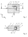
- FIGS 1 to 4 show the switching states in a schematic representation a switching element 1, which is based on the principle of the liquid film.
- the switching element has a base body 2 made of transparent material a recess 3.
- the recess 3 comprises an interface 4, which strikes the incident light 5 at an angle of approximately 45 °.
- the rear side surfaces 6,7 of the recess 3 close with the Interface 4 an angle of 45 °.
- On the bottom and top the recess 3 is delimited by flat surfaces 8, 9 with Side surfaces 6.7 form an angle of 90 °.
- the recess 3 there is a body 10 with the cross section of a isosceles triangle.
- the triangular body is in the Recess 3 by means of a not shown in Figures 1 to 4 Actuator in the XY plane to form a narrow Gap 12 between its side surfaces and the side surfaces 6,7 or the interface 4 of the recess 3 and its top and bottom and the upper and lower surfaces 8.9 of the recess are movable.
- the Recess 3 also contains a liquid 13 with a Refractive index, which is approximately equal to the refractive index of the material which consist of the base body and the movable body. The The amount of liquid is such that due to Adhesive forces form a liquid film in the narrow gap 12 which remaining area in the recess 3 essentially not with the Liquid is filled.
- the interface is in the switching state shown in FIGS. 1 and 2 4, which is incident on the incident light 5, is not wetted with the liquid 13, so that the incident light is totally reflected at the interface.
- the incident light 5 and the light 14 emerging from the base body 2 encloses an angle of 90 °.
- the triangular body 10 by means of Actuator moved in the recess 3 that the narrow gap 12 between the interface 4 and the body 10, so that the area of the interface where the incident light 5 strikes is completely covered by the liquid 13.
- the movable Body 10 that shown in Figures 3a and 4a and 3b and 4b Take positions. The only decisive thing is that the in the beam path of the incident light 5 lying area of the interface 4 completely with the Liquid is covered. Since the base body 1, the liquid 13 and the triangular body 10 have approximately the same refractive index occurs the incident light 5 from the base body 2 again without its Change direction. At right angles to the side faces 6,7 incident light is also not reflected in this switching state, but can pass freely through the switching element (emerging light beam 14).
- FIGS. 5a and 5b show an embodiment of the switching element 15, that both according to the principle of the liquid film and according to the Principle of displacement can work.
- the switching element 15 differs differs from that described with reference to FIGS. 1 to 4 Switching element 1 in that the triangular body 16 in vertical Movable in the recess 20 of the base body 21 is guided.
- FIGS. 5a and 5b show the embodiment of a principle of the switching element 15 based on the liquid film according to FIGS. 5a and 5b in section in a schematic representation.
- Owing to Adhesive forces remain the liquid 22 during the movement of the triangular body 16 between the surfaces.
- the interface 19 is not with the Liquid film 22 covered, so that the incident light 23 totally reflected becomes.
- the triangular body 16 is at the height of the Beam path, the incident light 23 is not deflected ( Figure 6b).
- the liquid film also acts as a sliding film and reduces wear of the reflective surfaces.
- the triangular body 16 is actuated by means of a electromagnetic actuator 24 which is outside the Recess is arranged above the movable body 16.
- the Actuator 24 has an electromagnet 25, for. B. with a lithographically produced coil, with the movable body 16 on its top and bottom with a magnetic or magnetizable Material 16 'is provided.
- Figures 7 and 8 show the embodiment of a on the principle of Displacement-based switching element according to Figure 5a or 5b in section in a schematic representation, the elements that correspond to the elements of the 5a to 6b correspond with the are provided with the same reference numerals.
- the movable body 16 will by means of the electromagnetic actuator 24 in vertical Moving direction.
- the fluid level is outside the range of the Interface 19, where the incident light 23 strikes.
- the liquid is from a triangular body 16 displaced so that the lower region of the recess completely with a Medium is filled up that about the same refractive index as that Has base body ( Figure 8).
- Figures 9a and 9b show one based on the principle of the liquid film based embodiment, the recess 3 and the movable Body 10 in the plane of the beam path of a light beam have a square cross-section. Between the parallel surfaces 60, 61 the recess 3 and the movable body 10 is located Liquid film 26.
- Figure 9a shows the switching element in the transmitting state. The movable body is located in FIG. 9b 10 outside the beam path, so that the two surfaces 60, 61 are not with the liquid is wetted. With this switching element the input E1 optionally connected to output A1 or A2, whereby at the same time input E2 is connected to output A2 or A1.
- FIGS. 10a and 10b show a further embodiment of the Switching element with one in the plane of the beam path of a light beam parallelogram-shaped cross section of the recess 3 and movable body 10.
- This switching element can operate on the principle of Liquid film and on the principle of displacement or one A combination of both principles can be operated.
- the two in parallel Side surfaces 60, 61 of the recess 3 are so far apart that in contrast to Figures 9a and 9b, the input E2 and the Output A1 not in the transmitting switching state with each other are connected.
- the input is in FIG. 10a E1 connected to output A2.
- Figure 10b shows the reflective Switching state in which the inputs E1 and E2 with the outputs A1 or A2 are connected.
- FIGS. 11a and 11b Another exemplary embodiment is shown in FIGS. 11a and 11b.
- the recess 3 and the movable body 10 have the shape here an isosceles triangle.
- the angle between the two Side surfaces 60, 61 is approximately 45 ° here.
- Figure 11a Transmitting switching state shown, in which the input E1 with the Output A2 is connected.
- Figure 11b Transmitting switching state shown, in which the input E1 with the Output A2 is connected.
- the reflective switching state Figure 11b
- FIG Transmitting switching state shown.
- this switching element has the same mode of operation as that switching element shown in Figure 11b.
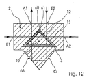
- Surfaces 62, 63 on the base body 2 which here have an angle of approximately 90 ° take a beam of light from the input E2 in the transmitting Switching state through the recess 3 in the direction of the exit A1 reflects. It is preferably located outside the switch body 2 optically thinner medium, so that it is reflected on the surfaces 62, 63 is a total reflection.
- these surfaces 62, 63 before outer To protect influences they can also take the form of an additional one Recess in the base body 2 be accommodated.
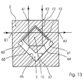
- the principle of the deflection of a transmitting shown in Figure 12 Light beam is also the representation of a transmissive Switching element in Figure 13 on the basis.
- the two are against it opposite surfaces 64, 65 of the movable body 10, due to the greater distance to the side surfaces 66, 67 of the recess, not wetted with the liquid 13.
- the two surfaces 64, 65 take the Angle of about 90 ° to each other, so that one from the input E2 coming and passing through the surface 61 of the recess 3 Light beam on these two surfaces 64, 65 in the direction of the exit A1 is totally reflected.
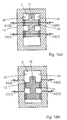
- a switching element is in the transmitting switching state in FIG. 14a shown, which serves as an optical multiple switch. All four areas of the Cross-section square recess 3 serve as interfaces to optional transmission or reflection of light. In the illustrated here Examples are inputs E1, E2, E3 and E4 with outputs A2, A3, A4 or A1 connected. In the reflective shown in Figure 14b Switching status are inputs E1, E2, E3 and E4 with outputs A1, A2, A3 or A4 connected.
- Figure 15 shows a switching element with several optical inputs and Outputs in the reflective switching state.
- On an interface 4 of the triangular recess 3 meet three light rays from the entrances E1, E2 and E3 and are towards the exits A1, A2 and A3 totally reflected.
- the incident light rays hit the here indicated outputs B1, B2 and B3.
- the incoming and the reflected light rays are essentially in one plane.
- an optical multiple switch forms the plane of the incident light rays with the plane of their reflected Light rays an angle of preferably 70 ° to 110 °.
- Figure 16a shows the transmitting switching state.
- the inputs E1 (1) and E1 (2) are connected to the outputs A2 (1) and A2 (2).
- the movable body 10 is shaped to have larger areas Cross-section and intermediate areas of smaller cross-section having. The areas of larger cross-section are so close to that Recess 3 that there between the movable body 10th and the interface 60, 61 of the recess 3 forms a liquid film 13. Between the areas of smaller cross-section of the movable body and the interface 60, 61 of the recess 3 there is no liquid film.
- the movable body 10 To switch from the transmitting to the reflecting state arrive, the movable body 10 only needs to be moved as far that an area of smaller cross section of the movable body comes to rest, so that the interfaces 60,61 in Region of the beam path are not wetted with the liquid 13 (FIG 16b).
- the exits A2 (1) and A2 (2) shown here Rays of light represent those coming from inputs E2 (1) and E2 (2) light rays reflected at the interface 61.
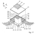
- FIG. 17 shows a 4x4 matrix switch with which each of the 4 optical inputs N 1 to N 4 can be switched to each of the 4 optical outputs M 1 to M 4 .
- the matrix switch has a flat base body 30, which consists of a base plate 31, a structured middle plate 32 and a cover plate 33.
- the structured plate 32 accommodates switching elements 1, 15 arranged in the manner of a 4x4 matrix, of the type described above.
- the recesses of the switching elements 1, 15, which are covered with the upper plate 33, are provided with the reference symbol 34 in FIG.
- the input and output fibers 35 to 38 and 39 to 42 are arranged in a cascade manner in the channels 43 to 46 and 47 to 50 of the structured plate 32 in order to ensure a uniform optical path length regardless of the respective switching state.
- the input channels 43 to 46 run approximately at right angles to the output channels 47 to 50, the interfaces of the recesses 34 of the switching elements 1, 15 being arranged at an angle of approximately 45 ° to the input and output channels.
- Ball lenses 53 are provided for collimating or focusing the light.
- the ball lenses 53 are inserted into depressions 54 of the structured plate 32 of the base body 30, which are arranged between the light exit ends of the input fibers 35-38 or output fibers 39-42 and the switching elements 1, 15.
- a further plate 51 is fastened on the cover plate 33 of the base body 30, in which the electromagnets 52 of the actuating device assigned to the individual switching elements are integrated.
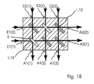
- FIG. 18 shows a further embodiment of a switching arrangement with 5 optical inputs E1 (1), E1 (2) and E2 (1), E2 (2), E2 (3) and 5 optical inputs Outputs A1 (1), A1 (2) and A2 (1), A2 (2), A2 (3) and 2x3 switching elements according to the invention, each with two parallel ones Side surfaces in a matrix arrangement.
- the input and output optical fibers and optical elements for beam focusing are omitted.
- the Switching elements in the matrix positions (1, 1) and (2, 2) are in this Example switched to reflection, while the other switching elements in the Figure 18 shown hatched, are switched to transmission.
- the inputs E1 (1), E1 (2), E2 (1), E2 (2), E2 (3) with the outputs A1 (1), A1 (2), A2 (1), A2 (2) and A1 (3) optically connected.
- FIG. 19 shows an embodiment of a switching arrangement with three diagonally arranged switching elements 1a, 1b, 1c in a schematic representation, in which three optical inputs N 1 to N 3 optionally on three optical outputs A 1 to A 3 or on three optical outputs B 1 to B 3 can be switched.
- the switching element 1a is assigned to the input N 1 and the output A 1 or B 1
- the switching element 1b is the input N 2 and the output A 2 or B 2
- the switching element 1c is the input N 3 and the output A 3 or B 3 assigned. If the switching elements 1a, 1b, 1c are switched to the transmitting state, the inputs N 1 , N 2 , N 3 are connected to the outputs A 1 or A 2 or A 3 .
- the light In the reflective switching state, the light is deflected so that the inputs N 1 , N 2 , N 3 are connected to the outputs B 1, B 2 and B 3 , respectively. If only one switching of the three switching elements into the transmitting or reflecting switching state is desired, instead of three individual switching elements, only a correspondingly larger switching element can be provided, on the interface of which the light from the three optical channels is incident (FIG. 15).
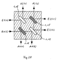
- Figure 20 shows an embodiment of a switching arrangement, which differs from the embodiment shown in Figure 18 differs in that the Inputs E1 (1) and E2 (2) the inputs E2 (1) and E2 (2) are opposite.
- the outputs are also corresponding arranged opposite each other.
- Such an arrangement is possible if always at least one switching element 1.15 between the Switching elements located opposite inputs on reflection is switched. Depending on the width of the switching elements 1.15 are the opposite inputs and outputs slightly offset from each other arranged.
- the switching elements must have two surfaces to reflect the light exhibit. Since the left input channels always only on the lower ones Output channels are switched and the right input channels always only on the upper output channels, there is no offset of the light rays by the width of the switch cell instead, as is the case with the Embodiment according to Figure 18 may be the case.
Landscapes
- Physics & Mathematics (AREA)
- General Physics & Mathematics (AREA)
- Optics & Photonics (AREA)
- Mechanical Light Control Or Optical Switches (AREA)
Description
eine auf dem Prinzip des Flüssigkeitsfilms beruhende Ausführungsform des Schaltelements in schematischer Darstellung, wobei das Schaltelement den Schaltzustand der Reflexion einnimmt,
einen Schnitt durch das Schaltelement von Figur 1 entlang der Linie A-A',
das Schaltelement von Figur 1 im transmittierenden Schaltzustand,
das Schaltelement von Figur 1 im transmittierenden Schaltzustand, wobei der bewegbare Körper eine andere Position einnimmt als in Figur 3a,
einen Schnitt durch das Schaltelement von Figur 3a entlang der Linie B-B',
einen Schnitt durch das Schaltelement von Figur 3b entlang der Linie C-C',
eine Ausführungsform, die sowohl auf dem Prinzip des Flüssigkeitsfilms als auch auf dem Prinzip der Verdrängung beruhen kann, wobei das Schaltelement den Schaltzustand der Reflexion einnimmt,
das Schaltelement von Figur 5a im transmittierenden Schaltzustand,
einen Schnitt durch ein auf dem Prinzip des Flüssigkeitsfilms beruhendes Schaltelement im reflektierenden Schaltzustand nach Figur 5a entlang der Linie D-D',
einen Schnitt durch ein auf dem Prinzip des Flüssigkeitsfilms beruhendes Schaltelement im transmittierenden Schaltzustand nach Figur 5b entlang der Linie E-E',
einen Schnitt durch ein auf dem Prinzip der Verdrängung beruhendes Schaltelement im reflektierenden Schaltzustand nach Figur 5a entlang der Linie D-D',
einen Schnitt durch ein auf dem Prinzip der Verdrängung beruhendes Schaltelement im reflektierenden Schaltzustand nach Figur 5b entlang der Linie E-E',
eine auf dem Prinzip des Flüssigkeitsfilms beruhende Ausführungsform des Schaltelements, wobei das Schaltelement im transmittierenden Zustand ist und die Ausnehmung und der bewegbare Körper einen viereckigen Querschnitt aufweisen,
das Schaltelement nach Figur 9a im reflektierenden Zustand,
ein Ausführungsbeispiel des Schaltelements mit einem parallelogrammförmigen Querschnitt der Ausnehmung und des bewegbaren Körpers, wobei das Schaltelement im transmittierenden Zustand ist,
das Schaltelement nach Figur 10a im reflektierenden Zustand,
ein weiteres Ausführungsbeispiel des Schaltelements mit einem dreieckförmigen Querschnitt der Ausnehmung und des bewegbaren Körpers, wobei das Schaltelement im transmittierenden Zustand ist,
das Schaltelement nach Figur 11a im reflektierenden Zustand,
ein Schaltelement nach Figur 11a mit zwei zusätzlichen reflektierenden Flächen am Basiskörper,
ein Schaltelement nach dem in Figur 12 dargestellten Prinzip, wobei der bewegbare Körper zwei zusätzliche reflektierende Flächen aufweist,
ein Ausführungsbeispiel des Schaltelements als optischer Mehrfachschalter im transmittierenden Schaltzustand mit quadratischem Querschnitt der Ausnehmung und des bewegbaren Körpers,
der optische Mehrfachschalter nach Figur 14a im reflektierenden Schaltzustand,
ein Ausführungsbeispiel des Schaltelements als optischer Mehrfachschalter, wobei die einfallenden und die reflektierten Lichtstrahlen in einer Ebene liegen,
ein weiteres Ausführungsbeispiel des Schaltelements im transmittierenden Zustand als Mehrfachschalter mit einem bewegbaren Körper mit im Querschnitt unterschiedlichen Bereichen, dargestellt in der Ebene der transmittierten Lichtstrahlen,
das Schaltelement nach Figur 16a im reflektierenden Schaltzustand, wobei die Ebene der einfallenden Lichtstrahlen mit der hier nicht dargestellten Ebene ihrer reflektierten Lichtstrahlen einen Winkel von etwa 90° bildet,
eine Schaltanordnung mit 4 Ein- und 4 Ausgangskanälen mit nach Art einer 4x4 Matrix angeordneten Schaltelementen in perspektivischer schematischer Darstellung,
eine Schaltanordnung mit 2x3 Ein- und 2x3 Ausgangskanälen mit nach Art einer 2x3 Matrix angeordneten Schaltelementen in schematischer Darstellung,
eine Schaltanordnung mit 3 Ein- und 2x3 Ausgangskanälen mit 3 nach Art einer Diagonalen einer 3x3 Matrix angeordneten Schaltelementen in schematischer Darstellung,
eine der in Figur 18 gezeigten Schaltanordnung entsprechende Ausführungsform, bei der die Eingänge und Ausgänge gegenüberliegend angeordnet sind.
- 1
- Schaltelement
- 2
- Basiskö rper
- 3
- Ausnehmung
- 4
- Grenzfläche
- 5
- einfallender Lichtstrahl
- 6
- rückwärtige Seitenfläche der Ausnehmung
- 7
- rückwärtige Seitenfläche der Ausnehmung
- 8
- Unterseite der Ausnehmung
- 9
- Oberseite der Ausnehmung
- 10
- bewegbarer Körper
- 12
- Spalt
- 13
- Flüssigkeit
- 14
- austretender Lichtstrahl
- 15
- Schaltelement
- 16
- bewegbarer Körper
- 16'
- magnetische Schicht
- 19
- Grenzfläche
- 20
- Ausnehmung
- 21
- Basiskörper
- 22
- Flüssigkeit
- 23
- einfallendes Licht
- 24
- Betätigungseinrichtung
- 25
- Elektromagnet
- 26
- Flüssigkeit
- 30
- Basiskörper
- 31
- Bodenplatte
- 32
- strukturierte Platte
- 33
- Deckplatte
- 34
- Ausnehmung
- 35 - 38
- Eingangsfaser
- 39 - 42
- Ausgangsfaser
- 43 - 46
- Kanal
- 47 - 50
- Kanal
- 51
- Platte mit Betätigungseinrichtung
- 52
- Elektromagnet
- 53
- Kugellinse
- 54
- Vertiefung
- 60
- Seitenfläche der Ausnehmung
- 61
- Seitenfläche der Ausnehmung
- 62
- zusätzliche Fläche des Basiskörpers
- 63
- zusätzliche Fläche des Basiskörpers
- 64
- Seitenfläche des bewegbaren Körpers
- 65
- Seitenfläche des bewegbaren Körpers
- 66
- Seitenfläche der Ausnehmung
- 67
- Seitenfläche der Ausnehmung
Claims (38)
- Optisches Schaltelement zum Ändern der Ausbreitungsrichtung von mindestens einem Lichtstrahl mit einem zumindest entlang des Strahlengangs lichtdurchlässigen Basiskörper (2), der zur Bildung mindestens einer Grenzfläche (4), auf die der einfallende Lichtstrahl (5) auftrifft, zwischen einem optisch dichteren Medium und einem optisch dünneren Medium eine Ausnehmung (3) aufweist, die eine Flüssigkeit (13) und einen in der Ausnehmung (3) bewegbaren Körper (10,16) enthält,
wobei der Basiskörper (2) und der bewegbare Körper (10,16) zumindest in Teilen aus den im verwendeten Wellenlängenbereich transparenten Materialien bestehen, und die Flüssigkeit derart beschaffen und der bewegbare Körper derart ausgebildet und in der Ausnehmung zwischen einer Position, in der das optische Schaltelement in dem transmittierenden Schaltzustand ist, und einer Position, in der das optische Schaltelement in dem reflektierenden Schaltzustand, bewegbar ist,
daß im transmittierenden Schaltzustand sich der bewegbare Körper (10,16) im Strahlengang des einfallenden Lichts befindet und zumindest der im Strahlengang des einfallenden Lichts liegende Bereich eines Spaltes (12) zwischen der Grenzfläche (4) und der Oberfläche des bewegbaren Körpers vollständig mit der Flüssigkeit gefüllt ist,
wobei im reflektierenden Schaltzustand zumindest der im Strahlengang des einfallenden Lichts liegende Bereich der Grenzfläche (4) frei von der Flüssigkeit ist, so daß das einfallende Licht an der Grenzfläche im wesentlichen reflektiert wird, und - Optisches Schaltelement nach Anspruch 1, wobei der Basiskörper (2), der bewegbare Körper (10,16) und die Flüssigkeit (13) im wesentlichen den gleichen Brechungsindex aufweisen.
- Optisches Schaltelement nach den Ansprüchen 1 oder 2, wobei der bewegbare Körper (10, 16) mit mindestens einem Körper oder einer Schicht (16') aus magnetischem oder magnetisierbaren Material versehen ist und daß die Betätigungseinrichtung (24) vorzugsweise mindestens einen außerhalb der Ausnehmung angeordneten Elektromagneten (25) und/oder Permanentmagneten aufweist.
- Optisches Schaltelement nach den Ansprüchen 1 oder 2, wobei der bewegbare Körper (10, 16) mit mindestens einer vorzugsweise piezoelektrischen oder thermoelektrischen Betätigungsreinrichtung verbunden ist.
- Optisches Schaltelement nach einem der Ansprüche 1 bis 4, wobei die Ausnehmung (20) soweit mit der Flüssigkeit (26) gefüllt ist, daß im reflektierenden Schaltzustand der im Strahlengang des einfallenden Lichts (23) liegende Bereich der Grenzfläche außerhalb des Flüssigkeitsspiegels liegt, und daß im transmittierenden Schaltzustand der bewegbare Körper derart in die Flüssigkeit bewegt ist, daß der im Strahlengang des einfallenden Lichts liegende Bereich des Spaltes durch Verdrängung mit Flüssigkeit gefüllt ist.
- Optisches Schaltelement nach einem der Ansprüche 1 bis 5, wobei ein Flüssigkeitsfilm zwischen einem Teil der Oberfläche des bewegbaren Körpers (16) und einem Teil der Wandung der Ausnehmung (20) ausgebildet ist und daß der bewegbare Körper (16) derart in der Ausnehmung bewegbar ist, daß im transmittierenden Schaltzustand der im Strahlengang des einfallenden Lichts (23) liegende Bereich des Spaltes zwischen der Grenzfläche (19) und der Oberfläche des bewegbaren Körpers (16) mit dem Flüssigkeitsfilm gefüllt ist, und daß im reflektierenden Schaltzustand der im Strahlengang des einfallenden Lichts (23) liegende Bereich der Grenzfläche (19) frei von dem Flüssigkeitsfilm ist.
- Optisches Schaltelement nach einem der Ansprüche 1 bis 6, wobei die Ausnehmung (3) und der bewegbare Körper (10, 16) in der Ebene des Strahlengangs eines Lichtstrahls im wesentlichen einen dreieckförmigen Querschnitt aufweisen.
- Optisches Schaltelement nach einem der Ansprüche 1 bis 6, wobei die Ausnehmung (3) und der bewegbare Körper (10, 16) in der Ebene des Strahlengangs eines Lichtstrahls im wesentlichen einen viereckförmigen Querschnitt aufweisen.
- Optisches Schaltelement nach einem der Ansprüche 1 bis 8, wobei die Grenzfläche (4,19) so zu dem einfallenden Lichtstrahl angeordnet ist, daß in dem reflektierenden Schaltzustand das einfallende Licht an der Grenzfläche im wesentlichen totalreflektiert wird.
- Optisches Schaltelement nach Anspruch 9, wobei der Winkel zwischen dem einfallenden Lichtstrahl und der Grenzfläche (4, 19) 40° bis 50° beträgt.
- Optisches Schaltelement nach den Ansprüchen 1 bis 10, wobei die Grenzfläche (4,19) so geformt ist, daß im reflektierenden Schaltzustand Licht durch Reflexion an der Grenzfläche (4, 19) zumindest teilweise gebündelt wird.
- Optisches Schaltelement nach den Ansprüchen 1 bis 11, wobei der Basiskörper (2) mindestens eine weitere Ausnehmung zur Aufnahme und Halterung von Lichtwellenleitern, insbesondere von einzelnen Fasern, Faserbändchen oder Fasersteckern, aufweist.
- Optisches Schaltelement nach den Ansprüchen 1 bis 12, wobei der Basiskörper (2) mindestens eine weitere Ausnehmung zur Aufnahme von optischen Elementen, insbesondere von Mikrolinsen oder GRIN-Linsen, aufweist.
- Optisches Schaltelement nach den Ansprüchen 1 bis 13, wobei der Basiskörper (2) mindestens eine weitere Ausnehmung aufweist, die so geformt und im Strahlengang angeordnet ist, daß sie einfallendes Licht im wesentlichen bündelt.
- Optisches Schaltelement nach einem der Ansprüche 1 bis 14, wobei eine Fläche der Ausnehmung zur wahlweisen Reflexion oder Transmission von Lichtstrahlen vorgesehen ist.
- Optisches Schaltelement nach einem der Ansprüche 1 bis 14, wobei zwei Flächen (60, 61) der Ausnehmung (3) zur wahlweisen Reflexion oder Transmission von Lichtstrahlen vorgesehen sind.
wobei mindestens eine Betätigungseinrichtung (24) zum Umschalten des bewegbaren Körpers (10,16) zwischen dem transmittierenden und dem reflektierenden Schaltzustand vorgesehen ist. - Optisches Schaltelement nach Anspruch 16, wobei die beiden reflektierenden Flächen (60,61) im wesentlichen parallel zueinander angeordnet sind.
- Optisches Schaltelement nach Anspruch 16, wobei die beiden reflektierenden Flächen (60, 61) in einem Winkel von 70° bis 110° zueinander angeordnet sind.
- Optisches Schaltelement nach einem der Ansprüche 1 bis 18, wobei mindestens zwei optische Eingänge in einem Winkel von 70° bis 110° zueinander angeordnet sind.
- Optisches Schaltelement nach dem Anspruch 18 oder 19, wobei die Ausnehmung (3) und der bewegbare Körper (10) in der Ebene des Strahlengangs eines Lichtstrahls im wesentlichen einen Querschnitt eines gleichschenkligen Dreiecks aufweisen.
- Optisches Schaltelement nach einem der Ansprüche 18 bis 20, wobei der Basiskörper (2) zwei zusätzliche Flächen (62, 63) aufweist, die im wesentlichen gegenüber den beiden reflektierenden Flächen (60, 61) der Ausnehmung (3) angeordnet sind und daß diese beiden Flächen des Basiskörpers einen Winkel von 70° bis 110° bilden und so angeordnet sind, daß im transmittierenden Schaltzustand mindestens ein Lichtstrahl an beiden Flächen (62, 63) totalreflektiert wird.
- Optisches Schaltelement nach Anspruch 21, wobei die beiden zusätzlichen Flächen (62, 63) durch mindestens eine zusätzliche Ausnehmung im Basiskörper gebildet werden.
- Optisches Schaltelement nach dem Anspruch 18 oder 19, wobei die Ausnehmung und der bewegbare Körper (10) in der Ebene des Strahlengangs eines Lichtstrahls im wesentlichen einen viereckförmigen Querschnitt aufweisen,
und daß zumindest der im Strahlengang liegende Bereich des Spalts zwischen den beiden reflektierenden Flächen (60, 61) der Ausnehmung (3) und den benachbarten Flächen des bewegbaren Körpers im transmittierenden Schaltzustand mit der Flüssigkeit (13) gefüllt ist, während die diesen beiden Flächen des bewegbaren Körpers gegenüberliegende dritte und vierte Fläche (64, 65) des bewegbaren Körpers nicht mit der Flüssigkeit bedeckt ist, so daß im transmittierenden Schaltzustand mindestens ein Lichtstrahl an beiden Flächen (64, 65) im bewegbaren Körper totalreflektiert wird. - Optisches Schaltelement nach einem der Ansprüche 1 bis 23, wobei mindestens drei Flächen der Ausnehmung (3) zur wahlweisen Reflexion oder Transmission von Lichtstrahlen vorgesehen sind.
- Optisches Schaltelement nach Anspruch 24, wobei die Ausnehmung und der bewegbare Körper in der Ebene des Strahlengangs eines Lichtstrahls im wesentlichen einen Querschnitt eines Quadrats aufweisen.
- Optisches Schaltelement nach einem der Ansprüche 1 bis 25, wobei mindestens ein Teil der einfallenden Lichtstrahlen so zu der Fläche (4) der Ausnehmung (3), von der sie im reflektierenden Schaltzustand reflektiert werden, angeordnet ist, daß dieser Teil der einfallenden Lichtstrahlen mit den entsprechenden reflektierten Lichtstrahlen im wesentlichen in einer Ebene liegt.
- Optisches Schaltelement nach einem der Ansprüche 1 bis 25, wobei mindestens ein Teil der einfallenden Lichtstrahlen so zu der Fläche der Ausnehmung, von der sie im reflektierenden Schaltzustand reflektiert werden, angeordnet ist, daß die Ebene dieses Teils der einfallenden Lichtstrahlen mit der Ebene der entsprechenden reflektierten Lichtstrahlen einen Winkel von 70° bis 110° bildet.
- Optisches Schaltelement nach einem der Ansprüche 1 bis 27, wobei der bewegbare Körper (10) mindestens zwei Bereiche mit parallel zu der Ebene des Strahlengangs eines Lichtstrahls größeren Querschnitts aufweist, die so nahe an mindestens eine Fläche (60, 61) der Ausnehmung angrenzen, daß zwischen diesen Bereichen und der entsprechenden Fläche der Ausnehmung ein Flüssigkeitsfilm bestehen bleibt, während zwischen den anderen Bereichen mit kleinerem Querschnitt des bewegbaren Körpers und der entsprechenden Fläche der Ausnehmung kein Flüssigkeitsfilm besteht.
- Optisches Schaltelement nach einem der Ansprüche 1 bis 28, wobei der Basiskörper (2) und/ oder der bewegbare Körper (10, 16) zumindest zu einem Teil aus einem transparenten Polymer, einem Glas oder einem transparenten nach einem Sol-Gel-Prozeß hergestellten Material besteht.
- Schaltanordnung mit N optischen Eingängen (E1,E2) und M optischen Ausgängen (A1,A2) mit N, M ≥ 1, die nach Art einer NxM Schalt-Matrix mit N-Zeilen und M-Spalten angeordnete Schaltelemente (1,15) aufweist, wobei jedes optische Schaltelement zum Ändern der Ausbreitungsrichtung von mindestens einem Lichtstrahl (5) dient und
einen zumindest entlang des Strahlengangs lichtdurchlässigen Basiskörper (2) enthält, der zur Bildung mindestens einer Grenzfläche (4), auf die der einfallende Lichtstrahl (5) auftrifft, zwischen einem optisch dichteren Medium und einem optisch dünneren Medium eine Ausnehmung (3) aufweist, die eine Flüssigkeit (13) und einen bewegbaren Körper (10,16) enthält, wobei der Basiskörper (2) und der bewegbare Körper (10,16) zumindest in Teilen aus den im verwendeten Wellenlängenbereich transparenten Materialien bestehen, und die Flüssigkeit derart beschaffen und der bewegbare Körper derart ausgebildet und in der Ausnehmung zwischen einer Position, in der das optische Schaltelement (1,15) in dem transmittierenden Schaltzustand ist, und einer Position, in der das optische Schaltelement in dem reflektierenden Schaltzustand ist, bewegbar ist,
daß im transmittierenden Schaltzustand sich der bewegbare Körper (10,16) im Strahlengang des einfallenden Lichts befindet und zumindest der im Strahlengang des einfallenden Lichts liegende Bereich eines Spaltes (12) zwischen der Grenzfläche (4) und der Oberfläche des bewegbaren Körpers vollständig mit der Flüssigkeit gefüllt ist, und in dem reflektierenden Schaltzustand zumindest der im Strahlengang des einfallenden Lichts liegende Bereich der Grenzfläche (4) frei von der Flüssigkeit ist, so daß das einfallende Licht an der Grenzfläche im wesentlichen reflektiert wird,
und mit mindestens einer Betätigungseinrichtung (24) zum Umschalten des Schaltelements zwischen dem transmittierenden und dem reflektierenden Schaltzustand durch Bewegen des bewegbaren Körpers (10,16). - Schaltanordnung nach Anspruch 30, wobei die Ausnehmungen (34) der Schaltelemente (1,15) nach Art einer NxM-Matrix in einem gemeinsamen Basiskörper angeordnet sind.
- Schaltanordnung nach Anspruch 30, wobei die Schaltelemente als einzelne Schaltmodule realisiert und in nach Art einer NxM-Matrix angeordneten Ausnehmungen einer Matrixplatte angeordnet sind.
- Schaltanordnung nach Anspruch 30, 31 oder 32, wobei der Basiskörper (30) bzw. die Matrixplatte N parallele Kanäle zur Aufnahme von N-Eingangslichtwellenleitern (35-38) und M parallele Kanäle zur Aufnahme von M Ausgangslichtwellenleiter (39-42) aufweist, wobei die Eingangskanäle im Winkel von 70° bis 110° zu den Ausgangskanälen und die Grenzflächen der Ausnehmungen der Schaltelemente in einem Winkel von 40° bis 50° zu den Eingangs- bzw. Ausgangskan älen angeordnet sind.
- Schaltanordnung nach einem der Ansprüche 30 bis 33, wobei die Schaltanordnung zusätzlich N zweite optische Ausgänge aufweist, die auf der den N esten optischen Eingängen gegenüberliegenden Seite der Schaltanordnung angeordnet sind.
- Schaltanordnung nach einem der Ansprüche 30 bis 34, wobei die Schaltanordung M zweite optische Eingänge aufweist, die auf der den M ersten optischen Ausgängen gegenüberliegenden Seite der Schaltanordnung angeordnet sind.
- Schaltanordnung nach einem der Ansprüche 30 bis 35, wobei N Schaltelemente (1, 15) nach Art einer Diagonalen einer NxN Matrix angeordnet sind, wobei die Zahl N der optischen Eingänge gleich der Zahl M der optischen Ausgänge ist.
- Schaltanordnung nach einem der Ansprüche 30 bis 36, wobei im Strahlengang zwischen den Eingangs- und Ausgangskanälen und den Ausnehmungen der Schaltelemente (54) Vertiefungen vorgesehen sind, in die optische Elemente (53), insbesondere Mikrolinsen oder GRIN-Linsen, eingesetzt sind.
- Schaltanordnung nach einem der Ansprüche 30, 31 oder 33 bis 37, wobei der Basiskörper (30) aus einer Bodenplatte (31), einer strukturierten Platte (32) und einer Deckplatte (33) zusammengesetzt ist.
Applications Claiming Priority (3)
| Application Number | Priority Date | Filing Date | Title |
|---|---|---|---|
| DE19711564A DE19711564C2 (de) | 1997-03-20 | 1997-03-20 | Optisches Schaltelement und Schaltanordnung |
| DE19711564 | 1997-03-20 | ||
| PCT/EP1998/001600 WO1998043124A1 (de) | 1997-03-20 | 1998-03-19 | Optisches schaltelement und schaltanordnung |
Publications (2)
| Publication Number | Publication Date |
|---|---|
| EP0968452A1 EP0968452A1 (de) | 2000-01-05 |
| EP0968452B1 true EP0968452B1 (de) | 2002-07-17 |
Family
ID=7823975
Family Applications (1)
| Application Number | Title | Priority Date | Filing Date |
|---|---|---|---|
| EP98917009A Expired - Lifetime EP0968452B1 (de) | 1997-03-20 | 1998-03-19 | Optisches schaltelement und schaltanordnung |
Country Status (5)
| Country | Link |
|---|---|
| US (1) | US6345132B1 (de) |
| EP (1) | EP0968452B1 (de) |
| AU (1) | AU7037898A (de) |
| DE (2) | DE19711564C2 (de) |
| WO (1) | WO1998043124A1 (de) |
Families Citing this family (24)
| Publication number | Priority date | Publication date | Assignee | Title |
|---|---|---|---|---|
| US6404942B1 (en) * | 1998-10-23 | 2002-06-11 | Corning Incorporated | Fluid-encapsulated MEMS optical switch |
| US6396972B1 (en) * | 2000-02-09 | 2002-05-28 | Agilent Technologies, Inc. | Thermally actuated optical add/drop switch |
| US6459828B1 (en) * | 2000-04-29 | 2002-10-01 | Agilent Technologies, Inc. | Rearrangeable optical add/drop multiplexor switch with low loss |
| US6591033B2 (en) * | 2000-11-06 | 2003-07-08 | Jack Gershfeld | Optical matrix switcher |
| US6463192B1 (en) * | 2001-02-26 | 2002-10-08 | K2 Optronics, Inc. | Non-blocking micro-optic switch matrix for use in fiber optic systems |
| US7016560B2 (en) | 2001-02-28 | 2006-03-21 | Lightwave Microsystems Corporation | Microfluidic control for waveguide optical switches, variable attenuators, and other optical devices |
| WO2002069016A2 (en) * | 2001-02-28 | 2002-09-06 | Lightwave Microsystems Corporation | Microfluid control for waveguide optical switches, variable attenuators, and other optical devices |
| US6507682B2 (en) | 2001-04-06 | 2003-01-14 | Ngk Insulators, Ltd. | Optical switch |
| US6526197B2 (en) * | 2001-04-09 | 2003-02-25 | Adc Telecommunications, Inc. | MEMS optical balanced path switch |
| DE10129923C1 (de) * | 2001-06-21 | 2003-02-27 | Inst Mikrotechnik Mainz Gmbh | Optische Schalteinrichtung |
| JP2003005098A (ja) * | 2001-06-25 | 2003-01-08 | Teijin Seiki Co Ltd | 光路切換装置 |
| US6752526B2 (en) * | 2001-11-19 | 2004-06-22 | Control Devices | Combined optical light pipe and protective enclosure |
| DE10162816A1 (de) * | 2001-12-19 | 2003-07-03 | Sunyx Surface Nanotechnologies | Optischer Schalter |
| DE10248867B4 (de) * | 2002-10-18 | 2009-01-22 | Daimler Ag | Optischer Schalter |
| US6798937B1 (en) * | 2003-04-14 | 2004-09-28 | Agilent Technologies, Inc. | Pressure actuated solid slug optical latching relay |
| US6920259B2 (en) * | 2003-04-14 | 2005-07-19 | Agilent Technologies, Inc. | Longitudinal electromagnetic latching optical relay |
| KR20070048236A (ko) * | 2004-09-09 | 2007-05-08 | 코닌클리케 필립스 일렉트로닉스 엔.브이. | 반사형 전기습윤 렌즈 |
| US8885991B2 (en) | 2009-12-21 | 2014-11-11 | Hewlett-Packard Development Company, L.P. | Circuit switched optical interconnection fabric |
| WO2011084155A1 (en) | 2010-01-06 | 2011-07-14 | Hewlett-Packard Development Company, L.P. | Optical interconnect |
| US8559774B2 (en) * | 2011-03-31 | 2013-10-15 | Harris Corporation | Optical device having an elastomeric waveguide switch body and related methods |
| WO2016064399A1 (en) * | 2014-10-23 | 2016-04-28 | Hewlett Packard Enterprise Development Lp | Optical port-shuffling module |
| US10677995B2 (en) | 2014-10-23 | 2020-06-09 | Hewlett Packard Enterprise Development Lp | Optical fiber interface for optical device package |
| US10534148B2 (en) | 2014-10-24 | 2020-01-14 | Hewlett Packard Enterprise Development Lp | Optical interconnect device |
| WO2016122490A1 (en) | 2015-01-28 | 2016-08-04 | Hewlett Packard Enterprise Development Lp | Laser-written optical routing systems and method |
Family Cites Families (8)
| Publication number | Priority date | Publication date | Assignee | Title |
|---|---|---|---|---|
| US2997922A (en) * | 1958-04-24 | 1961-08-29 | Edward K Kaprelian | Light valve |
| US3338656A (en) * | 1963-12-12 | 1967-08-29 | Barnes Eng Co | Frustrated internal reflection modulator and a method of making the same |
| GB1494150A (en) | 1975-12-09 | 1977-12-07 | Standard Telephones Cables Ltd | Optical switch arrangement |
| FR2524658A1 (fr) * | 1982-03-30 | 1983-10-07 | Socapex | Commutateur optique et matrice de commutation comprenant de tels commutateurs |
| FR2553906B1 (fr) * | 1983-10-21 | 1986-10-17 | Thomson Csf | Dispositif de commutation optique a commande electrique |
| JPS60185918A (ja) * | 1984-03-05 | 1985-09-21 | Canon Inc | 光変調方法 |
| US5311410A (en) * | 1992-10-29 | 1994-05-10 | Hughes Aircraft Company | Distributed lighting system with fiber optic controls |
| DE19527566A1 (de) * | 1995-07-27 | 1997-01-30 | Sel Alcatel Ag | Optischer Umschalter |
-
1997
- 1997-03-20 DE DE19711564A patent/DE19711564C2/de not_active Expired - Fee Related
-
1998
- 1998-03-19 US US09/381,409 patent/US6345132B1/en not_active Expired - Fee Related
- 1998-03-19 WO PCT/EP1998/001600 patent/WO1998043124A1/de not_active Ceased
- 1998-03-19 AU AU70378/98A patent/AU7037898A/en not_active Abandoned
- 1998-03-19 DE DE59804804T patent/DE59804804D1/de not_active Expired - Lifetime
- 1998-03-19 EP EP98917009A patent/EP0968452B1/de not_active Expired - Lifetime
Also Published As
| Publication number | Publication date |
|---|---|
| US6345132B1 (en) | 2002-02-05 |
| DE19711564C2 (de) | 1999-07-08 |
| DE59804804D1 (de) | 2002-08-22 |
| DE19711564A1 (de) | 1998-10-01 |
| EP0968452A1 (de) | 2000-01-05 |
| WO1998043124A1 (de) | 1998-10-01 |
| AU7037898A (en) | 1998-10-20 |
Similar Documents
| Publication | Publication Date | Title |
|---|---|---|
| DE19711564C2 (de) | Optisches Schaltelement und Schaltanordnung | |
| EP1062537B1 (de) | Optischer schalter und modulares schaltsystem aus optischen schaltelementen | |
| EP1316165B1 (de) | Optischer modifizierer und verfahren zur herstellung hierfür | |
| DE3010347C2 (de) | Einrichtung zur Verbindung von Lichtleitern | |
| DE102009027348A1 (de) | Optische Strahlweiche | |
| EP0927376A1 (de) | Verfahren zur herstellung eines lichtleiterschalters und lichtleiterschalter | |
| EP0053324A2 (de) | Optisches Verzweigungsglied | |
| DE2905916A1 (de) | Faseroptische uebertragungsvorrichtung | |
| DE19711559C2 (de) | Optischer Mehrfachschalter | |
| DE3101415C2 (de) | ||
| DE19706053B4 (de) | Schaltanordnung zum Schalten und Einkoppeln eines Lichtbündels in mindestens eine Ausgangsfaser | |
| DE102011100720A1 (de) | Opto-mechanische Weiche | |
| DE4301455A1 (de) | Anordnung zur Ankopplung von Lichtwellenleiterenden an Sende- oder Empfangselemente | |
| DE20105786U1 (de) | Optischer Umschalter | |
| DE4234916C2 (de) | Optischer Schalter | |
| DE4204567C2 (de) | Optischer Schalter | |
| EP1373952B1 (de) | Optischer umschalter | |
| EP1337900B1 (de) | Schaltungsanordnung | |
| DE4133220A1 (de) | Fasern-linsen-anordnung zum optischen koppeln | |
| DE2951020C2 (de) | ||
| DE10129923C1 (de) | Optische Schalteinrichtung | |
| DE3618037C1 (en) | Optical component | |
| DE102004027219A1 (de) | Optischer Schalter | |
| EP1477839A2 (de) | Steuerbare Fresnellinsenanordnung | |
| DE102004027222A1 (de) | Optischer Multimodeschalter |
Legal Events
| Date | Code | Title | Description |
|---|---|---|---|
| PUAI | Public reference made under article 153(3) epc to a published international application that has entered the european phase |
Free format text: ORIGINAL CODE: 0009012 |
|
| 17P | Request for examination filed |
Effective date: 19990914 |
|
| AK | Designated contracting states |
Kind code of ref document: A1 Designated state(s): CH DE FR GB LI |
|
| GRAG | Despatch of communication of intention to grant |
Free format text: ORIGINAL CODE: EPIDOS AGRA |
|
| 17Q | First examination report despatched |
Effective date: 20010917 |
|
| GRAG | Despatch of communication of intention to grant |
Free format text: ORIGINAL CODE: EPIDOS AGRA |
|
| GRAH | Despatch of communication of intention to grant a patent |
Free format text: ORIGINAL CODE: EPIDOS IGRA |
|
| GRAH | Despatch of communication of intention to grant a patent |
Free format text: ORIGINAL CODE: EPIDOS IGRA |
|
| GRAA | (expected) grant |
Free format text: ORIGINAL CODE: 0009210 |
|
| RAP1 | Party data changed (applicant data changed or rights of an application transferred) |
Owner name: INSTITUT FUER MIKROTECHNIK MAINZ GMBH |
|
| AK | Designated contracting states |
Kind code of ref document: B1 Designated state(s): CH DE FR GB LI |
|
| PG25 | Lapsed in a contracting state [announced via postgrant information from national office to epo] |
Ref country code: GB Free format text: LAPSE BECAUSE OF FAILURE TO SUBMIT A TRANSLATION OF THE DESCRIPTION OR TO PAY THE FEE WITHIN THE PRESCRIBED TIME-LIMIT Effective date: 20020717 Ref country code: FR Free format text: LAPSE BECAUSE OF NON-PAYMENT OF DUE FEES Effective date: 20020717 |
|
| REG | Reference to a national code |
Ref country code: GB Ref legal event code: FG4D Free format text: NOT ENGLISH |
|
| REG | Reference to a national code |
Ref country code: CH Ref legal event code: EP |
|
| REF | Corresponds to: |
Ref document number: 59804804 Country of ref document: DE Date of ref document: 20020822 |
|
| GBV | Gb: ep patent (uk) treated as always having been void in accordance with gb section 77(7)/1977 [no translation filed] |
Effective date: 20020717 |
|
| EN | Fr: translation not filed | ||
| PG25 | Lapsed in a contracting state [announced via postgrant information from national office to epo] |
Ref country code: LI Free format text: LAPSE BECAUSE OF NON-PAYMENT OF DUE FEES Effective date: 20030331 Ref country code: CH Free format text: LAPSE BECAUSE OF NON-PAYMENT OF DUE FEES Effective date: 20030331 |
|
| PLBE | No opposition filed within time limit |
Free format text: ORIGINAL CODE: 0009261 |
|
| STAA | Information on the status of an ep patent application or granted ep patent |
Free format text: STATUS: NO OPPOSITION FILED WITHIN TIME LIMIT |
|
| 26N | No opposition filed |
Effective date: 20030422 |
|
| REG | Reference to a national code |
Ref country code: CH Ref legal event code: PL |
|
| PGFP | Annual fee paid to national office [announced via postgrant information from national office to epo] |
Ref country code: DE Payment date: 20100326 Year of fee payment: 13 |
|
| PG25 | Lapsed in a contracting state [announced via postgrant information from national office to epo] |
Ref country code: DE Free format text: LAPSE BECAUSE OF NON-PAYMENT OF DUE FEES Effective date: 20111001 |
|
| REG | Reference to a national code |
Ref country code: DE Ref legal event code: R119 Ref document number: 59804804 Country of ref document: DE Effective date: 20111001 |