EP0968026B1 - Chambre d'acces vasculaire - Google Patents
Chambre d'acces vasculaire Download PDFInfo
- Publication number
- EP0968026B1 EP0968026B1 EP98903549A EP98903549A EP0968026B1 EP 0968026 B1 EP0968026 B1 EP 0968026B1 EP 98903549 A EP98903549 A EP 98903549A EP 98903549 A EP98903549 A EP 98903549A EP 0968026 B1 EP0968026 B1 EP 0968026B1
- Authority
- EP
- European Patent Office
- Prior art keywords
- port
- access
- passage
- conduit
- needle
- Prior art date
- Legal status (The legal status is an assumption and is not a legal conclusion. Google has not performed a legal analysis and makes no representation as to the accuracy of the status listed.)
- Expired - Lifetime
Links
Images


Classifications
-
- A—HUMAN NECESSITIES
- A61—MEDICAL OR VETERINARY SCIENCE; HYGIENE
- A61M—DEVICES FOR INTRODUCING MEDIA INTO, OR ONTO, THE BODY; DEVICES FOR TRANSDUCING BODY MEDIA OR FOR TAKING MEDIA FROM THE BODY; DEVICES FOR PRODUCING OR ENDING SLEEP OR STUPOR
- A61M39/00—Tubes, tube connectors, tube couplings, valves, access sites or the like, specially adapted for medical use
- A61M39/02—Access sites
- A61M39/0208—Subcutaneous access sites for injecting or removing fluids
-
- A—HUMAN NECESSITIES
- A61—MEDICAL OR VETERINARY SCIENCE; HYGIENE
- A61M—DEVICES FOR INTRODUCING MEDIA INTO, OR ONTO, THE BODY; DEVICES FOR TRANSDUCING BODY MEDIA OR FOR TAKING MEDIA FROM THE BODY; DEVICES FOR PRODUCING OR ENDING SLEEP OR STUPOR
- A61M1/00—Suction or pumping devices for medical purposes; Devices for carrying-off, for treatment of, or for carrying-over, body-liquids; Drainage systems
- A61M1/36—Other treatment of blood in a by-pass of the natural circulatory system, e.g. temperature adaptation, irradiation ; Extra-corporeal blood circuits
- A61M1/3621—Extra-corporeal blood circuits
- A61M1/3653—Interfaces between patient blood circulation and extra-corporal blood circuit
- A61M1/3656—Monitoring patency or flow at connection sites; Detecting disconnections
-
- A—HUMAN NECESSITIES
- A61—MEDICAL OR VETERINARY SCIENCE; HYGIENE
- A61M—DEVICES FOR INTRODUCING MEDIA INTO, OR ONTO, THE BODY; DEVICES FOR TRANSDUCING BODY MEDIA OR FOR TAKING MEDIA FROM THE BODY; DEVICES FOR PRODUCING OR ENDING SLEEP OR STUPOR
- A61M1/00—Suction or pumping devices for medical purposes; Devices for carrying-off, for treatment of, or for carrying-over, body-liquids; Drainage systems
- A61M1/36—Other treatment of blood in a by-pass of the natural circulatory system, e.g. temperature adaptation, irradiation ; Extra-corporeal blood circuits
- A61M1/3621—Extra-corporeal blood circuits
- A61M1/3653—Interfaces between patient blood circulation and extra-corporal blood circuit
- A61M1/3659—Cannulae pertaining to extracorporeal circulation
-
- A—HUMAN NECESSITIES
- A61—MEDICAL OR VETERINARY SCIENCE; HYGIENE
- A61M—DEVICES FOR INTRODUCING MEDIA INTO, OR ONTO, THE BODY; DEVICES FOR TRANSDUCING BODY MEDIA OR FOR TAKING MEDIA FROM THE BODY; DEVICES FOR PRODUCING OR ENDING SLEEP OR STUPOR
- A61M39/00—Tubes, tube connectors, tube couplings, valves, access sites or the like, specially adapted for medical use
- A61M2039/0036—Tubes, tube connectors, tube couplings, valves, access sites or the like, specially adapted for medical use characterised by a septum having particular features, e.g. having venting channels or being made from antimicrobial or self-lubricating elastomer
- A61M2039/009—Means for limiting access to the septum, e.g. shields, grids
-
- A—HUMAN NECESSITIES
- A61—MEDICAL OR VETERINARY SCIENCE; HYGIENE
- A61M—DEVICES FOR INTRODUCING MEDIA INTO, OR ONTO, THE BODY; DEVICES FOR TRANSDUCING BODY MEDIA OR FOR TAKING MEDIA FROM THE BODY; DEVICES FOR PRODUCING OR ENDING SLEEP OR STUPOR
- A61M2205/00—General characteristics of the apparatus
- A61M2205/19—Constructional features of carpules, syringes or blisters
- A61M2205/192—Avoiding coring, e.g. preventing formation of particles during puncture
- A61M2205/195—Avoiding coring, e.g. preventing formation of particles during puncture by the needle tip shape
-
- A—HUMAN NECESSITIES
- A61—MEDICAL OR VETERINARY SCIENCE; HYGIENE
- A61M—DEVICES FOR INTRODUCING MEDIA INTO, OR ONTO, THE BODY; DEVICES FOR TRANSDUCING BODY MEDIA OR FOR TAKING MEDIA FROM THE BODY; DEVICES FOR PRODUCING OR ENDING SLEEP OR STUPOR
- A61M25/00—Catheters; Hollow probes
- A61M25/0021—Catheters; Hollow probes characterised by the form of the tubing
- A61M25/0023—Catheters; Hollow probes characterised by the form of the tubing by the form of the lumen, e.g. cross-section, variable diameter
Definitions
- the present invention relates generally to the design and use of medical devices, and more particularly to the design and use of an implantable port for establishing temporary access to a patient's vascular system for hemodialysis and other extracorporeal blood treatments.
- Access to a patient's vascular system can be established by a variety of temporary and permanently implanted devices. Most simply, temporary access can be provided by the direct percutaneous introduction of a needle through the patient's skin and into a blood vessel. While such a direct approach is relatively simple and suitable for applications, such as intravenous feeding, intravenous drug delivery, and other applications which are limited in time, they are not suitable for hemodialysis and other extracorporeal procedures that must be repeated periodically, often for the lifetime of the patient.
- the port includes a chamber on an access region, such as a septum, and the chamber is attached to an implanted catheter which in turn is secured to a blood vessel.
- the catheter In the case of veins, the catheter is typically indwelling and in the case of arteries, the catheter may be attached by conventional anastomosis.
- implantable ports typically include a needle-penetrable septum which permits the percutaneous penetration of a needle into the internal chamber.
- the chamber is connected to one end of the catheter, and the other end of the catheter is indwelling in the blood vessel.
- Such designs suffer from a number of problems. Repeated penetration of the septum often leads to degradation over time, presenting a substantial risk of small particulates entering the blood stream and/or need to periodically replace the port.
- the passage of blood through the chamber or plenum will often encounter regions of turbulence or low flow, either of which can degrade the quality of blood over time.
- the access ports preferably will comprise a valve structure for isolating the port from an associated implanted catheter when the port is not in use.
- the valve will preferably provide little or no structure within the blood flow lumen of the access port and will even more preferably not require passage of a needle or other access tube through the seating portion of a valve in order to open the valve.
- the port structure including the valve elements therein will have a substantially uniform cross-sectional area and will present no significant constrictions or enlargements to disturb fluid flow therethrough.
- the port designs will permit percutaneous access using a conventional needle, such as a fistula needle, without damage to either the port or the needle. Still more preferably, the needles or other devices used to access the port will resist accidental dislodgement from the port without requiring significant extra structure or additional components. Ports and valves according to the present invention will meet at least some of these objectives.
- Patents which name William Ensminger as an inventor include U.S. Patent Nos. 4,569,675; 4,534,759; 4,181,132; 3,998,222; WO 96/31246, and WO 96/25196.
- U.S. Patent No. 5,637,088 describes a septum-type implantable port which employs a dual needle to help prevent dislodgement.
- US-A-5417656 encloses an implantable port having a valve which opens directly in response to passage of a needle through the valve.
- Embodiments of the present invention provide improved access ports, particularly vascular access ports which may be used for high volume withdrawal and/or return of blood or other fluids particularly for patients undergoing an extracorporeal blood therapy, such as hemodialysis, hemofiltration, hemodiafiltration, apheresis, or the like.
- the vascular access ports allow for high volumetric rates of blood or other fluid flow therethrough, typically allowing for rates above 250 ml/min, usually above 300 ml/min, preferably at least 400 ml/min, and often 500 ml/min or higher, using a single needle or other access device.
- Such high volumetric flow rates are quite advantageous in reducing the time required for performing the extracorporeal blood treatment, particularly for otherwise lengthy treatments which require large total volumes of treated blood, such as hemofiltration.
- the access ports are particularly useful for establishing vascular access, the ports will also be useful for accessing other body lumens and cavities, such as the peritoneal cavity, and the like.
- the access ports of the present invention have a number of other advantageous features.
- the access ports are adapted to receive standard sharp access needles, including large-diameter fistula needles, without substantial damage to either the port or the needle.
- the port design also provides for simple "locking” and “unlocking” of the needle or access device as it is inserted and removed from the port, as described in more detail below.
- percutaneous access to a blood vessel is provided by maintaining a conduit between an implanted access port and the blood vessel.
- the access port is isolated from the blood vessel by externally clamping the conduit, which is typically formed at least partly from a resilient material, such as silicone rubber.
- Percutaneous insertion of an access tube into the access port relieves the external clamping of the conduit in order to permit fluid flow therethrough.
- Use of external clamping for isolating the access port is particularly advantageous since no internal valve structure is required to define a valve seat within the flow lumen.
- a proximal end of the conduit is disposed within the access port while a distal end of the conduit is disposed outside of the access port, usually being attached to the blood vessel or other body lumen or being connected to an implanted catheter or other conduit which, in turn, is attached to the blood vessel.
- the conduit will usually comprise a single continuous tube, but could alternatively comprise a number of separate axial portions having different compositional or structural characteristics which are joined together, e.g. at a port on the housing.
- a portion of the length of the conduit could be composed of a relatively rigid material, such as a hard plastic or metal, while only that portion which is subjected to external clamping need be composed of a flexible material which can be sealed by clamping.
- conduits could be bifurcated for connection to more than one body lumen site.
- the conduit is disposed entirely within the access port and a connected is provided on the access port for attachment to a separate catheter which may in turn be connected to the blood vessel.
- the access port may be employed to receive blood flow from a blood vessel or provide other fluid flows, e.g. dialysate for peritoneal dialysis, typically an artery.
- a second access port is provided for connection to a vein for a return of blood to the patient.
- Any of the extracorporeal treatment modalities described above could be employed with the blood flow between the arterial access port and the venous access port.
- the access ports of the present invention could be used singly infusing fluids, drugs, and other substances to the patient.
- the conduit is maintained between an implanted access port and a blood vessel of the patient.
- An access tube is percutaneously inserted into the access port so that the access tube engages a linkage which opens a valve structure within the port or the conduit.
- the valve structure is located remotely from that portion of the access port into which the access tube has been inserted and may be present in the conduit itself or in a separate pinch tube or assembly within the port.
- the linkage may be mechanical or hydraulic, usually being mechanically coupled to a spring-loaded clamp which constricts a flexible (collapsible) portion of the conduit when the linkage is not engaged by the access tube.
- a hydraulic linkage could be provided where a closing force on the tube is hydraulically relieved or a valve opened by insertion of the access tube.
- percutaneous access to a patient's blood vessel is provided by maintaining a conduit between an implanted access port and the blood vessel.
- An access tube is percutaneously inserted into a tube seat within the access port to establish a generally fluid tight seal therein.
- the access tube actuates a linkage to open a valve structure to permit flow through the conduit.
- the valve structure will usually be internal to the port but, in some cases, could be located outside of the port itself.
- the tube seat comprises a tapered bore within the access port which frictionally engages the outside access tube as the tube is inserted into the bore.
- the linkage may take a variety of forms, including clamp valves as described above.
- the linkage may also be in the form of a sliding valve assembly, where the access tube advances a valve component to align flow passages therethrough to open the flow path within the port.
- the tube seat will remain locked in its depressed condition until the access tube is removed from the base.
- a hard material preferably a material harder than the needle or other access device which is to be used
- the likelihood of damage to the valve can be greatly reduced.
- the tapered tube seat design is not prone to damaging needles when they are inserted into the port.
- the port of the present invention is particularly suited for use with self-penetrating, sharpened needles, such as fistula needles, unlike many ports of the prior art.
- percutaneous access to a patient's blood vessels is provided by maintaining a conduit between an implanted access port and a blood vessel.
- An access tube is percutaneously inserted into the access port in a generally vertical orientation, i.e., in a direction normal or perpendicular to the surface of the patient's skin through which the access tube is being introduced.
- the passage in the access port is connected to the conduit through an elbow at an angle of from 75° to 105°. The ability to vertically introduce the access tube greatly simplifies alignment of the access tube with the passage in the port.
- Apparatus according to the present invention comprise implantable ports having a base with a passage for receiving an access tube, such as a needle, rigid catheter, cannula, or other conventional device for receiving or returning blood flow or other fluid.
- the flexible conduit is disposed within the base to establish fluid flow with an access tube which has been inserted through the passage.
- a linkage is further provided which opens the flexible conduit, typically by relieving an external clamp from over the conduit, when an access tube is present in the passage. The linkage further closes the flexible conduit when the access tube is absent from the passage.
- the linkage is part of or coupled to a valve assembly.
- the valve assembly may be a sliding valve and the linkage comprise a slide within the valve. In all cases, the linkage will be actuated by insertion of the access tube and will open the conduit, valve, or other part of the flow path at a location remote from the access tube.
- the conduit of the implantable port will usually have a proximal end disposed within the base and a distal end disposed outside the base.
- the distal end When disposed outside of the base, the distal end will typically be adapted for direct connection to a blood vessel, e.g., by including a cuff which may be connected to the blood vessel by an end-to-side anastomosis or a T-catheter which may be implanted within the lumen of the blood vessel.
- the conduit may terminate in a connector which is adapted for removable connection to one end of a separate implantable catheter which may be connected to the blood vessel.
- the flexible conduit may have a proximal end disposed within a base and a distal end which terminates on a luer or other conventional connector disposed on an external surface of the base.
- the access port may be connected to a separate, implantable catheter through the connector on the surface of the base.
- the passage in the base comprises a tapered bore which seals externally against a needle or other access tube as the tube is inserted into the bore.
- a flexible conduit is connected to an end of the tapered bore, and typically deflected at approximately a right angle (i.e., between 75° and 105°) to direct the conduit externally of the base.
- the tapered bore is formed in a slide of a sliding valve.
- an implantable port comprises a base having a passage and a flexible conduit, generally as described above.
- a clamp is disposed externally on the flexible conduit, wherein the clamp is closed over the conduit but opens to permit fluid flow through the conduit when an access tube is inserted into the passage within the base. Conversely, the clamp closes over the conduit when the access tube is removed from the passage.
- such an implantable port further comprises a linkage assembly including an actuator which responds to entry of the access tube into the passage and which opens the clamp in response to such passage. Likewise, the actuator will respond to removal of the access tube from the passage in the base and close the clamp in response to such removal.
- an implantable port comprises a base and a conduit, generally as described above.
- the passage within the base is oriented along a generally vertical access, i.e., normal to the portion of the patient's skin through which the access tube is to be introduced, and the conduit is disposed along a generally horizontal access.
- an implantable port comprises a base having a first passage for receiving access tube and a flexible conduit disposed through a second passage in the base.
- An actuator assembly is reciprocatably mounted in the base and includes a bore aligned with the first passage for receiving the access tube.
- the proximal end of the conduit is mechanically coupled to the bore in an actuator assembly, a spring urges the actuator assembly to a first position in the base wherein the flexible conduit is closed and is opened by insertion of the access tube into the first passage.
- the actuator assembly comprises a lower lip and the second passage in the base comprises an upper lip, wherein the upper lip and lower lip are opposed on opposite sides of the flexible conduit so that the flexible spring closes the lips together to close the lumen within the conduit when an access tube is inserted into the tube-receiving bore in the actuator.
- an implantable port comprises a base having a passage for receiving an access tube.
- a valve assembly is disposed in the base and includes a bore which is aligned with the passage in the base and which also receives the access tube.
- a pair of balls typically opposed stainless steel balls similar to small ball bearings, are disposed between the passage in the base and the bore in the valve. The balls are spring-biased to close or engage against the access device when it is inserted through the passage and port. In particular, the balls will lock the access tube in place by frictional engagement so that it is very difficult to accidentally dislodge the access tube without following a specific removal procedure.
- the access tube can be readily removed by simply twisting or turning it about its own longitudinal axis while gently pulling thereon.
- the access tube is firmly locked in place so that the likelihood of accidental removal is minimized, it can still be easily removed without damage to either the access tube or the port, or significant discomfort to the patient by a simple twisting and pulling procedure.
- an implantable port in yet another alternative apparatus includes a base, a passage in the base for receiving a needle or other access tube, and an internal valve which opens and closes in response to insertion of the access tube into the passage.
- the implantable port comprises a symmetric configuration where the passage is disposed at a central location in the top of the port.
- the passage has an entry aperture with an area in the range from 3 mm 2 to 20 mm 2 , more preferably from 5 mm 2 to 15 mm 2 .
- Such a port configuration facilitates percutaneous introduction of a needle or other access tube into the port. The user can manually locate the periphery of the port base, usually using one hand.
- the user can then insert the access tube in a generally vertical orientation directly into the center of the port where the entry aperture is located.
- access to the port is much simpler than with non-symmetric port configurations, particularly those ports which require the needle to enter in a non-vertical orientation relative to the patient's skin.
- Improved body lumen access systems comprise an implantable port and an access tube.
- a port having a passage for receiving the access tube where the passage is composed of a material which is harder than the port, wear on the passage of the port is greatly reduced, thus increasing the useful life of the port. This is particularly important where the port is to be directly accessed using a needle having a sharpened tip.
- the passage will be generally cylindrical and have a tapered portion which seals against the exterior of the needle or other access tube therein.
- Methods for accessing a body lumen comprise subcutaneously implanting a port and subcutaneously implanting a conduit.
- the port has an inlet adapted to receive an access tube with an outer diameter of at least 2 mm.
- the conduit is attached to an outlet of the port and has a lumen diameter of at least 2.5 mm.
- the method usually further comprises accessing the implanted port with an access tube having an outer diameter of at least 2 mm.
- Such methods permit flow rates of at least 250 ml/min to be established when a differential pressure between the body lumen and an outlet end of the access tube of at least 200 mmHg exists. Usually, higher flow rates as set forth above can also be achieved.
- the body lumen is a blood vessel and the fluid is blood, although the method is also useful for accessing other body lumens, e.g. the peritoneum or peritoneal dialysis.
- an implantable port comprising a base having an inlet passage adapted to receive an access tube with an outer diameter of at least 2 mm and an outlet passage.
- a valve is disposed in the base between the inlet passage and the outlet passage, and the valve is adapted to open in response to insertion of the access tube into the inlet passage.
- a means is provided for attaching an implantable conduit having a lumen diameter of at least 2.5 mm to the outlet passage of the base, e.g. a connector on the base or a conduit extending from the base and having a connector at its distal end.
- the implantable port is particularly useful in the method just described.
- the system may further comprise an implantable conduit having a lumen diameter of at least 2.5 mm.
- the present invention provides methods and apparatus for facilitating percutaneous access to a body lumen of a patient.
- body lumens include blood vessels, the peritoneal cavity, and the like.
- the methods are particularly useful for accessing blood vessels, including both arterial blood vessels and venous blood vessels. While the remaining description is directed particularly at blood vessels, it will be appreciated that the invention applies to all body lumens and cavities where selective percutaneous access might be desired.
- the ports can be used for introduction and removal of dialysate in peritoneal dialysis procedures.
- Access ports according to the present invention are implanted subcutaneously so that a passage therein lies a short distance beneath the surface of the patient's skin, typically being within 3 mm to 20 mm of the skin's surface.
- An access tube may then be percutaneously inserted into the passage in the access port in order to provide communication with the blood vessel or other body lumen via the access port.
- Such access can be provided for a variety of purposes, usually involving withdrawal of blood, the extracorporeal treatment of the withdrawn blood, and/or the return of the treated blood to the patient.
- Such extracorporeal blood treatment will most often be for hemodialysis, but can also be for hemofiltration, hemodiafiltration, apheresis, and the like.
- the access port of the present invention can be used for perfusing drugs, fluids, and other materials directly into a patient's circulation for a variety of purposes.
- Implantation of the access port and connection of the port to the target blood vessel or other body lumen is done via a conduit, at least a portion of which will be flexible.
- flexible it is meant that the conduit will be resilient and collapsible so that it may be externally clamped or otherwise deformed in order to prevent blood flow through the conduit when the access port is not in use.
- external clamping in order to close the conduit is particularly advantageous since no internal structure need be provided within the conduit which could interfere with blood flow and/or with insertion of a needle or other access tube into the conduit.
- the access tube will usually be a needle which can be directly pierced (percutaneously introduced) through the patient's skin and into the implanted port.
- the needle will usually have a sharpened tip in order to permit it to be self-introduced through the skin.
- access tubes having blunt distal ends could be used by first piercing the skin with a separate blade, stylet, needle, or the like, and thereafter introducing the access tube into the resulting incision or hole.
- the access tube could also be introduced using an internal stylet which is subsequently withdrawn, leaving the tube in place in the port.
- the port of the present invention can accept a wide variety of different access tubes, it is significant that it can be used with standard hypodermic needles, standard fistula needles, large fistula needles, e.g. 16 gauge, 14 gauge, or larger, and the like.
- Prior port designs which employ a septum require the use of relatively small non-coring Huber needles or the use of a combination tube/stylet in order to avoid significant damage to the septum.
- ports which employ slit valves through which a tube must pass such as many of the Ensminger designs described above.
- the needle or other access tube will be rigid and possess sufficient column strength in order to actuate a linkage for relieving clamping of the conduit, as described in more detail below.
- the port is also advantageous since it will not generally be damaged by use of an inappropriately sized needle or other access tube. While most prior art ports can be damaged through use of the wrong type or size of needle, the port of the present invention will not be damaged by larger needles (which simply engage the access aperture and do not pass into the port) or by smaller needles (which enter the access aperture but pass harmlessly into the interior of the base).
- the passage in the access port which receives the needle or other access tube will generally have at least one bend, usually a 90° elbow, which presents a surface which is engaged by a smaller needle.
- a material which is harder than the needle e.g. a stainless steel, the port will be protected from any damage from improper insertion of a small needle.
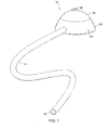
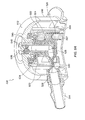
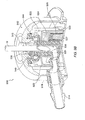
- FIG. 1 An exemplary access port 10 comprising a base 12 and flexible conduit 14 is illustrated in Figs. 1, 2, 2A, 3, and 3A.
- the flexible conduit 14 extends from the base 12 and terminates at a distal end 16 which is suitable for direct anastomosis (suturing) to a blood vessel.
- Suitable conduit structures are described in U.S. Patent No. 5,562,617.
- Exemplary conduit structures may be composed of silicone rubber. Conduit structures having different distal ends are described with reference to Figs. 4-8, hereinafter.
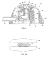
- the base 12 of access port 10 comprises an upper shell 18, a base plate 20, an internal cylinder 22, and a vertically reciprocating plunger 23 disposed within an actuator block 24, where the assembly of the plunger and actuator block are together disposed within the cylinder 22.
- a spring 26 urges the plunger 23 and actuator block 24 upwardly relative to the base 20.
- the conduit 14 is pinched closed between an upper lip 28 which is a portion of the wall of cylinder 22 and a lower lip 30 which is portion of the actuator block 24.
- a proximal end of the conduit 14 is connected to the lower end of a tube 32 which depends into an interior volume of the actuator block 24.
- the depending tube 32 provides an axial bore 34 for receiving a needle N, as illustrated in Figs. 3 and 3A.
- a tapered region 33 is formed near the upper end of axial bore 34 and is sized to engage and seal against the outer side wall of a needle or other access tube which is introduced into the bore, as best seen in Fig. 3.
- the needle N is introduced through an opening 36 at the upper end of the axial bore 34.
- the opening 36 has a slight chamfer (conical shape) to facilitate alignment of the needle N as it is introduced into the bore 34.
- a pair of balls 40 are disposed in an upper portion of the tube 32 and contained within a circular aperture 42 in the shell 18 on the actuator block 24 as in its raised configuration, as shown in Fig. 2.
- needle N When needle N is introduced through the opening 36, it will encounter the balls 40 and depress the plunger 23 and the actuator block 24 downward until the block reaches its lower configuration, as shown in Fig. 3. At that time, the balls 40 will move radially outward into an expanded portion 44 of the aperture 42. The balls 40 will thus become locked within the expanded region 44, holding the actuator block 24 in its lowered position, so long as the needle N remains in place.
- a silicone overmolding 50 is provided around the base of the access port 10 in order to facilitate implantation of the access port.
- a flange 52 extending radially outwardly from the base plate 20 will include holes (not illustrated) for suturing into tissue.
- the inclusion of the silicone overmolding 50 will prevent tissue ingrowth into the holes.
- a silicone seal 54 will be provided between an internal surface of the upper shell 18 and an upper portion of the tube 32. The silicone seal 54 prevents the intrusion of blood or other fluids from surrounding tissue and/or which may leak from the needle N into the interior of the access port 10.
- the axial bore 34 will be tapered in the downward direction.
- the size of the bore and degree of the taper will be selected to frictionally engage conventional needles or other access tubes so that a tight seal is formed as the access tubes are inserted into the axial bore 34.
- the taper also provides a stop so that the needle N will not penetrate into the horizontal lumen defined by the conduit 14.
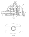
- the combination of needle, access port 10, and flexible conduit 14 provides a substantially continuous and smooth flow path for fluids from and/or to the patient's vascular system.
- the use of external clamping for closing flow through the conduit 14 eliminates the need for an internal valve structure within the conduit or elsewhere within the access port to define a valve seat, i.e. that portion of the valve which closes to inhibit flow therethrough.
- the particular linkage shown for relieving clamping from the flexible conduit is simple, reliable, and relatively inexpensive to produce. Very few moving parts are needed, yet a positive seal is reliably achieved every time the needle N is withdrawn from the access port 10.
- the clamp mechanism is locked in its open configuration to assure that full flow through the lumen of the flexible tube and other portions of the access port are maintained.
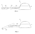
- the access port 10 may be modified to include a flexible conduit 114 having a distal fitting 116 for interconnection to a separate implantable catheter C.
- the fitting 116 will typically be a female fitting adapted to mate with a male fitting 118 at the proximal end of catheter C.
- Catheter C may be any known catheter intended for vascular attachment.
- catheter C may be an indwelling catheter for venous attachment, or it may be adapted for direct attachment to an artery in any known fashion. Provision of a connector intermediate the port and the vasculature or body lumen has a number of benefits. The ability to implant the port separately from the catheter simplifies implantation.
- FIG. 5 A further alternative structure for the access system 10 is illustrated in Fig. 5.
- flexible catheter 214 terminates in a T-connector 216.
- the T-connector is particularly suitable for implantation into arterial blood vessels.
- FIG. 6 yet another alternative flexible conduit 314 which may be attached to base 12 of an access port 10 is illustrated.
- the flexible conduit 314 is formed integrally with the silicone overmolding 350, thus firmly anchoring the conduit to the base 12. While the internal portions of the conduit 314 are identical to those of conduit 14 and the earlier embodiments, the external portion of the conduit includes rib structures 318 in order to enhance hoop strength of the conduit.
- a distal connector 316 is provided for connection to a male connector 320 at the proximal end of a catheter C'.
- the connector 320 comprises a metal, usually titanium, fitting which is received within the lumen of the silicone conduit 314.
- a clip 330 is provided for securing over the connectors 316 and 320 after the port 312 and catheter C' have both been implanted and connected.
- the catheter connection mechanism shown in Fig. 6 is particularly advantageous since the catheter C' may be disconnected from the flexible conduit 314 without having to disturb the implantation of the base 12 of the access port.
- a base unit 412 is substantially similar to base unit 12 described previously, except that the flexible conduit 416 terminates at an aperture through the upper shell 418.
- a metal fitting 420 is provided to permit external connection of a catheter to the base unit 12.
- the fitting 420 defines a lumen 422 which is aligned with the lumen of the flexible conduit 416.
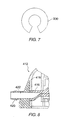
- FIG. 8 A presently preferred conduit connection where the internal pinch tube fits into a titanium nipple in the port housing is illustrated in Fig. 8.
- the conduit is attached externally to the titanium nipple and may terminate at its remote end (away from the housing) in any of the configurations previously discussed.
- an additional embodiment of an access port 500 constructed in accordance with the principles of the present invention includes a body 512 having a nipple 514 extending laterally outward from the body 512.
- the nipple 514 is suitable for connection to a flexible conduit (not shown).
- the body 512 includes an upper shell 518, a base plate 520, an internal cylinder 522, a vertically reciprocating plunger 23 and an actuator block 524.
- the plunger 23/actuator block 524 as shown in their vertically raised position in Fig. 9A and its vertically depressed or lowered configuration in Fig. 9B.
- the port embodiment 500 of Figs. 9A and 9B employs a separate pinch tube 525, where the pinch tube is pinched closed between an upper lip 528 which is part of the cylinder 522 and a lower lip 530 which is part of the reciprocating actuator block 524.
- the actuator block 524 is lowered, as shown in Fig. 9B, the external clamping of the pinch tube 525 is relieved.
- the actuator block 524 is urged upwardly by spring 526 which is mounted over a pin 527, and the plunger 523 comprises an axial bore 534 for receiving a needle N, as shown in Fig. 9B.
- the needle N passes through aperture 536 and into the passage 534 in the plunger 523.
- opposed balls 540 which first cause lowering of the plunger 523 and the actuator block 524 and then are captured in an expanded portion 544 of the passage 545, as illustrated in Fig. 9B.
- a valve structure is illustrated.
- a sliding valve 600 or a reciprocating block 602 is formed within the base enclosure 604 (only a portion of which is illustrated).
- the reciprocating block 602 defines an inlet portion 606 of a passage through the port.
- An outlet portion 608 of the passage is also provided in the port.
- a spring 610 urges the reciprocating block 602 upward so that a side portion 612 of the passage is out of alignment with the outlet portion 608.
- the sliding valve structure 600 is closed.
- the reciprocating block 602 is lowered so that the side branch 612 of the passage comes into alignment with the outlet portion 608, as illustrated in Fig. 10B.
- the valve is thus open.
- the valve can be held in the open position by a pair of opposed balls 620 which are received in an enlarged recess 622.
Landscapes
- Health & Medical Sciences (AREA)
- Heart & Thoracic Surgery (AREA)
- Vascular Medicine (AREA)
- Life Sciences & Earth Sciences (AREA)
- General Health & Medical Sciences (AREA)
- Anesthesiology (AREA)
- Biomedical Technology (AREA)
- Hematology (AREA)
- Veterinary Medicine (AREA)
- Animal Behavior & Ethology (AREA)
- Engineering & Computer Science (AREA)
- Public Health (AREA)
- Cardiology (AREA)
- Pulmonology (AREA)
- Infusion, Injection, And Reservoir Apparatuses (AREA)
- External Artificial Organs (AREA)
- Media Introduction/Drainage Providing Device (AREA)
Abstract
Claims (8)
- Chambre d'accès implantable comprenant une embase (12) ayant un passage (34) avec une entrée (36) destinée à recevoir un tube d'accès et une sortie (16, 316, 416), ladite chambre d'accès étant caractérisée par un mécanisme articulé (23) actionné par l'introduction du tube d'accès dans l'entrée et une structure de valve (28, 30) qui ouvre le passage en aval de l'entrée en réponse à l'actionnement du mécanisme articulé par le tube d'accès.
- Chambre d'accès implantable selon la revendication 1, dans laquelle la structure de valve comprend un conduit flexible et un clamp qui s'ouvre et se ferme autour du conduit en réponse à l'actionnement du mécanisme articulé.
- Chambre d'accès implantable selon la revendication 2, dans laquelle le passage et le conduit sont assemblés de manière à former une lumière à écoulement sensiblement continu qui est exempte de zones stagnantes.
- Chambre d'accès implantable selon l'une quelconque des revendications 2 ou 3, dans laquelle le conduit flexible possède une extrémité proximale disposée à l'intérieur de l'embase et une extrémité distale qui se termine sur un raccord sur une surface extérieure de l'embase.
- Chambre d'accès implantable selon l'une quelconque des revendications 2 à 4, dans laquelle le mécanisme articulé est actionné par le passage du tube d'accès dans le passage, qui conduit à par la libération d'un organe de blocage depuis l'extérieur du conduit flexible.
- Chambre d'accès implantable selon l'une quelconque des revendications précédentes, dans laquelle le passage comprend un alésage conique qui assure l'étanchéité contre le tube d'accès à mesure que ledit tube y est introduit.
- Chambre d'accès implantable selon la revendication 6, dans laquelle le conduit flexible est fixé à l'alésage conique selon un angle de 75° à 105°.
- Chambre d'accès implantable selon la revendication 1, dans laquelle la structure de valve comprend une valve coulissante, dans laquelle la valve coulissante comprend un bloc à mouvement alternatif dans lequel la partie d'entrée du passage est formée, dans laquelle le bloc à mouvement alternatif comprend le mécanisme articulé, et dans laquelle l'introduction d'un tube d'accès dans le bloc à mouvement alternatif fait coulisser le bloc de façon à aligner le passage réalisé dans celui-ci avec une partie aval du passage dans l'embase.
Applications Claiming Priority (5)
| Application Number | Priority Date | Filing Date | Title |
|---|---|---|---|
| US3612497P | 1997-01-21 | 1997-01-21 | |
| US36124P | 1997-01-21 | ||
| US08/942,990 US6007516A (en) | 1997-01-21 | 1997-10-02 | Valve port and method for vascular access |
| US942990 | 1997-10-02 | ||
| PCT/US1998/000934 WO1998031416A2 (fr) | 1997-01-21 | 1998-01-20 | Chambre et procede d'acces vasculaire |
Publications (2)
| Publication Number | Publication Date |
|---|---|
| EP0968026A2 EP0968026A2 (fr) | 2000-01-05 |
| EP0968026B1 true EP0968026B1 (fr) | 2003-10-15 |
Family
ID=26712831
Family Applications (1)
| Application Number | Title | Priority Date | Filing Date |
|---|---|---|---|
| EP98903549A Expired - Lifetime EP0968026B1 (fr) | 1997-01-21 | 1998-01-20 | Chambre d'acces vasculaire |
Country Status (8)
| Country | Link |
|---|---|
| US (1) | US6007516A (fr) |
| EP (1) | EP0968026B1 (fr) |
| JP (3) | JP4158124B2 (fr) |
| AU (1) | AU6029698A (fr) |
| CA (1) | CA2278122A1 (fr) |
| DE (1) | DE69818979T2 (fr) |
| ES (1) | ES2209109T3 (fr) |
| WO (1) | WO1998031416A2 (fr) |
Cited By (2)
| Publication number | Priority date | Publication date | Assignee | Title |
|---|---|---|---|---|
| GB2485172A (en) * | 2010-11-03 | 2012-05-09 | Cook Medical Technologies Llc | Haemostatic valve assembly |
| WO2022005790A1 (fr) * | 2020-07-02 | 2022-01-06 | Smiths Medical Asd, Inc. | Orifice conçu pour un accès fréquent |
Families Citing this family (126)
| Publication number | Priority date | Publication date | Assignee | Title |
|---|---|---|---|---|
| US7056316B1 (en) * | 1997-01-21 | 2006-06-06 | Vasca, Inc. | Valve port and method for vascular access |
| SE510303C2 (sv) * | 1997-10-21 | 1999-05-10 | Hemapure Ab | Anslutningsanordning för medicinska ändamål |
| FR2780893B1 (fr) * | 1998-07-10 | 2001-03-02 | Nmt Neurosciences Implants | Dispositifs pour le drainage de fluides biologiques |
| US8177762B2 (en) | 1998-12-07 | 2012-05-15 | C. R. Bard, Inc. | Septum including at least one identifiable feature, access ports including same, and related methods |
| AU2039900A (en) * | 1998-12-07 | 2000-06-26 | Std Manufacturing, Inc. | Implantable vascular access device |
| EP1154810A4 (fr) * | 1999-01-28 | 2003-01-02 | Vasca Inc | Procede et appareil permettant d'acceder par voie percutanee a un orifice implante commande par la pression |
| US6132415A (en) * | 1999-02-09 | 2000-10-17 | Vasca, Inc. | Systems and methods for removing retained fluids and infusing therapeutic fluids |
| WO2000062843A1 (fr) | 1999-04-20 | 2000-10-26 | Dsu Medical Corporation | Canule intraveineuse effilee |
| US6544214B1 (en) | 1999-05-25 | 2003-04-08 | Dsu Medical Corporation | Subcutaneous access needle and method |
| US6685694B2 (en) | 1999-07-23 | 2004-02-03 | Vasca, Inc. | Methods and kits for locking and disinfecting implanted catheters |
| US6679870B1 (en) | 1999-07-23 | 2004-01-20 | Vasca, Inc. | Methods and kits for locking and disinfecting implanted catheters |
| AU1208801A (en) * | 1999-11-01 | 2001-05-14 | Vasca, Inc. | Valve port and method for vascular access |
| WO2001078684A1 (fr) | 2000-04-14 | 2001-10-25 | Alphaport Llc | Port d'acces sous-cutane |
| WO2001080926A2 (fr) * | 2000-04-26 | 2001-11-01 | Std Manufacturing, Inc. | Dispositif d'acces pour hemodialyse implantable |
| US6620140B1 (en) * | 2000-06-30 | 2003-09-16 | Ethicon, Inc. | Method and an apparatus for a port access system |
| DE10105592A1 (de) | 2001-02-06 | 2002-08-08 | Achim Goepferich | Platzhalter zur Arzneistofffreigabe in der Stirnhöhle |
| US6682498B2 (en) | 2001-03-22 | 2004-01-27 | Vasca, Inc. | Methods and systems for subcutaneous graft implantation |
| US7144381B2 (en) | 2001-06-20 | 2006-12-05 | The Regents Of The University Of California | Hemodialysis system and method |
| WO2003020343A1 (fr) * | 2001-08-31 | 2003-03-13 | Disetronic Licensing Ag | Dispositif de raccordement pour acces a implantation percutanee et systeme d'acces comprenant ce dispositif de raccordement |
| US7232429B2 (en) * | 2002-04-08 | 2007-06-19 | Boston Scientific Corporation | Medical devices |
| US8317816B2 (en) | 2002-09-30 | 2012-11-27 | Acclarent, Inc. | Balloon catheters and methods for treating paranasal sinuses |
| US8608727B2 (en) | 2004-03-01 | 2013-12-17 | Smiths Medical Asd, Inc. | Delivery system and method |
| US9089258B2 (en) | 2004-04-21 | 2015-07-28 | Acclarent, Inc. | Endoscopic methods and devices for transnasal procedures |
| US9351750B2 (en) | 2004-04-21 | 2016-05-31 | Acclarent, Inc. | Devices and methods for treating maxillary sinus disease |
| US7361168B2 (en) * | 2004-04-21 | 2008-04-22 | Acclarent, Inc. | Implantable device and methods for delivering drugs and other substances to treat sinusitis and other disorders |
| US8702626B1 (en) | 2004-04-21 | 2014-04-22 | Acclarent, Inc. | Guidewires for performing image guided procedures |
| US7803150B2 (en) | 2004-04-21 | 2010-09-28 | Acclarent, Inc. | Devices, systems and methods useable for treating sinusitis |
| US7410480B2 (en) | 2004-04-21 | 2008-08-12 | Acclarent, Inc. | Devices and methods for delivering therapeutic substances for the treatment of sinusitis and other disorders |
| US7419497B2 (en) | 2004-04-21 | 2008-09-02 | Acclarent, Inc. | Methods for treating ethmoid disease |
| US20190314620A1 (en) | 2004-04-21 | 2019-10-17 | Acclarent, Inc. | Apparatus and methods for dilating and modifying ostia of paranasal sinuses and other intranasal or paranasal structures |
| US9554691B2 (en) | 2004-04-21 | 2017-01-31 | Acclarent, Inc. | Endoscopic methods and devices for transnasal procedures |
| US7462175B2 (en) | 2004-04-21 | 2008-12-09 | Acclarent, Inc. | Devices, systems and methods for treating disorders of the ear, nose and throat |
| US8764729B2 (en) | 2004-04-21 | 2014-07-01 | Acclarent, Inc. | Frontal sinus spacer |
| US10188413B1 (en) | 2004-04-21 | 2019-01-29 | Acclarent, Inc. | Deflectable guide catheters and related methods |
| US7654997B2 (en) | 2004-04-21 | 2010-02-02 | Acclarent, Inc. | Devices, systems and methods for diagnosing and treating sinusitus and other disorders of the ears, nose and/or throat |
| US20060004323A1 (en) | 2004-04-21 | 2006-01-05 | Exploramed Nc1, Inc. | Apparatus and methods for dilating and modifying ostia of paranasal sinuses and other intranasal or paranasal structures |
| US8932276B1 (en) | 2004-04-21 | 2015-01-13 | Acclarent, Inc. | Shapeable guide catheters and related methods |
| US8894614B2 (en) | 2004-04-21 | 2014-11-25 | Acclarent, Inc. | Devices, systems and methods useable for treating frontal sinusitis |
| US20070208252A1 (en) | 2004-04-21 | 2007-09-06 | Acclarent, Inc. | Systems and methods for performing image guided procedures within the ear, nose, throat and paranasal sinuses |
| US9399121B2 (en) | 2004-04-21 | 2016-07-26 | Acclarent, Inc. | Systems and methods for transnasal dilation of passageways in the ear, nose or throat |
| US8747389B2 (en) | 2004-04-21 | 2014-06-10 | Acclarent, Inc. | Systems for treating disorders of the ear, nose and throat |
| US20070167682A1 (en) | 2004-04-21 | 2007-07-19 | Acclarent, Inc. | Endoscopic methods and devices for transnasal procedures |
| US7559925B2 (en) | 2006-09-15 | 2009-07-14 | Acclarent Inc. | Methods and devices for facilitating visualization in a surgical environment |
| US8146400B2 (en) | 2004-04-21 | 2012-04-03 | Acclarent, Inc. | Endoscopic methods and devices for transnasal procedures |
| US20060063973A1 (en) | 2004-04-21 | 2006-03-23 | Acclarent, Inc. | Methods and apparatus for treating disorders of the ear, nose and throat |
| US9101384B2 (en) | 2004-04-21 | 2015-08-11 | Acclarent, Inc. | Devices, systems and methods for diagnosing and treating sinusitis and other disorders of the ears, Nose and/or throat |
| US7811266B2 (en) | 2004-07-13 | 2010-10-12 | Std Med, Inc. | Volume reducing reservoir insert for an infusion port |
| US20070191779A1 (en) * | 2004-08-31 | 2007-08-16 | Igor Shubayev | Percutaneous Vascular Access Device With External Disposable Connector |
| US7223257B2 (en) * | 2004-08-31 | 2007-05-29 | Igor Shubayev | Percutaneous vascular access device |
| US20060095021A1 (en) * | 2004-11-02 | 2006-05-04 | Casas-Bejar Jesus W | Introduction of agent with medical device |
| WO2006096686A1 (fr) | 2005-03-04 | 2006-09-14 | C.R. Bard, Inc. | Systemes et procedes d’identification d'orifice d’acces |
| US9474888B2 (en) | 2005-03-04 | 2016-10-25 | C. R. Bard, Inc. | Implantable access port including a sandwiched radiopaque insert |
| US8029482B2 (en) | 2005-03-04 | 2011-10-04 | C. R. Bard, Inc. | Systems and methods for radiographically identifying an access port |
| US7947022B2 (en) | 2005-03-04 | 2011-05-24 | C. R. Bard, Inc. | Access port identification systems and methods |
| EP1874393B1 (fr) | 2005-04-27 | 2017-09-06 | C.R.Bard, Inc. | Appareils de perfusion |
| JP5149158B2 (ja) | 2005-04-27 | 2013-02-20 | シー・アール・バード・インコーポレーテッド | 注入装置およびそれに関する方法 |
| US10307581B2 (en) | 2005-04-27 | 2019-06-04 | C. R. Bard, Inc. | Reinforced septum for an implantable medical device |
| US8951225B2 (en) | 2005-06-10 | 2015-02-10 | Acclarent, Inc. | Catheters with non-removable guide members useable for treatment of sinusitis |
| US20070073250A1 (en) * | 2005-07-08 | 2007-03-29 | Schneiter James A | Implantable port |
| US8114113B2 (en) | 2005-09-23 | 2012-02-14 | Acclarent, Inc. | Multi-conduit balloon catheter |
| BRPI0505102A (pt) | 2005-11-22 | 2007-08-07 | Renato Samy Assad | aperfeiçoamentos introduzidos em dispositivo de bandagem do tronco pulmonar |
| BRPI0602271B8 (pt) * | 2006-04-26 | 2021-06-22 | Augusto Silva Pires E Albuquerque Marcos | dispositivo de cateter venoso central de longa permanência parcialmente implantável |
| US8190389B2 (en) | 2006-05-17 | 2012-05-29 | Acclarent, Inc. | Adapter for attaching electromagnetic image guidance components to a medical device |
| US8167847B2 (en) | 2006-06-22 | 2012-05-01 | Excelsior Medical Corporation | Antiseptic cap and antiseptic cap equipped plunger and syringe barrel assembly |
| US20080039820A1 (en) * | 2006-08-10 | 2008-02-14 | Jeff Sommers | Medical Device With Septum |
| US9820688B2 (en) | 2006-09-15 | 2017-11-21 | Acclarent, Inc. | Sinus illumination lightwire device |
| US9265912B2 (en) | 2006-11-08 | 2016-02-23 | C. R. Bard, Inc. | Indicia informative of characteristics of insertable medical devices |
| US9642986B2 (en) | 2006-11-08 | 2017-05-09 | C. R. Bard, Inc. | Resource information key for an insertable medical device |
| US8439687B1 (en) | 2006-12-29 | 2013-05-14 | Acclarent, Inc. | Apparatus and method for simulated insertion and positioning of guidewares and other interventional devices |
| CN100435881C (zh) * | 2007-04-05 | 2008-11-26 | 武汉理工大学 | 有气囊式开关的经皮元件的制备方法 |
| WO2008124787A2 (fr) | 2007-04-09 | 2008-10-16 | Acclarent, Inc. | Système d'ethmoïdotomie et dispositifs espaceurs implantables capables de délivrer une substance thérapeutique pour le traitement de la sinusite paranasale |
| US8425469B2 (en) * | 2007-04-23 | 2013-04-23 | Jacobson Technologies, Llc | Systems and methods for controlled substance delivery network |
| US8118757B2 (en) | 2007-04-30 | 2012-02-21 | Acclarent, Inc. | Methods and devices for ostium measurement |
| US8485199B2 (en) | 2007-05-08 | 2013-07-16 | Acclarent, Inc. | Methods and devices for protecting nasal turbinate during surgery |
| CA2692142C (fr) | 2007-06-20 | 2016-07-26 | Medical Components, Inc. | Orifice d'acces veineux avec indices moules et/ou radio-opaques |
| US9610432B2 (en) | 2007-07-19 | 2017-04-04 | Innovative Medical Devices, Llc | Venous access port assembly with X-ray discernable indicia |
| EP3311877A1 (fr) | 2007-07-19 | 2018-04-25 | Medical Components, Inc. | Ensemble d'orifice d'accès veineux avec des inscriptions lisibles aux rayons x |
| US9579496B2 (en) | 2007-11-07 | 2017-02-28 | C. R. Bard, Inc. | Radiopaque and septum-based indicators for a multi-lumen implantable port |
| US8187163B2 (en) * | 2007-12-10 | 2012-05-29 | Ethicon Endo-Surgery, Inc. | Methods for implanting a gastric restriction device |
| US10206821B2 (en) | 2007-12-20 | 2019-02-19 | Acclarent, Inc. | Eustachian tube dilation balloon with ventilation path |
| EP2092943A1 (fr) * | 2008-02-21 | 2009-08-26 | Universität Bern | Accès implantable pour le retrait et/ou le retour de fluides |
| US8182432B2 (en) | 2008-03-10 | 2012-05-22 | Acclarent, Inc. | Corewire design and construction for medical devices |
| CA2723291C (fr) * | 2008-05-14 | 2017-08-15 | Becton, Dickinson And Company | Ensemble de perfusion separable avec interface nettoyable et fixation en ligne droite |
| CN102112040B (zh) | 2008-07-30 | 2015-04-01 | 阿克拉伦特公司 | 鼻旁孔口探示器器件和方法 |
| CN102159276B (zh) | 2008-09-18 | 2014-01-15 | 阿克拉伦特公司 | 用于治疗耳鼻喉科疾病的方法和设备 |
| ES2906416T3 (es) | 2008-10-31 | 2022-04-18 | Bard Inc C R | Sistemas y métodos para identificar una vía de acceso |
| US8932271B2 (en) | 2008-11-13 | 2015-01-13 | C. R. Bard, Inc. | Implantable medical devices including septum-based indicators |
| US11890443B2 (en) | 2008-11-13 | 2024-02-06 | C. R. Bard, Inc. | Implantable medical devices including septum-based indicators |
| US20100241155A1 (en) | 2009-03-20 | 2010-09-23 | Acclarent, Inc. | Guide system with suction |
| US7978742B1 (en) | 2010-03-24 | 2011-07-12 | Corning Incorporated | Methods for operating diode lasers |
| US8435290B2 (en) | 2009-03-31 | 2013-05-07 | Acclarent, Inc. | System and method for treatment of non-ventilating middle ear by providing a gas pathway through the nasopharynx |
| WO2010144533A1 (fr) * | 2009-06-09 | 2010-12-16 | Jacobson Technologies, Llc | Système et procédé d'administration régulée de substances |
| EP2451512A1 (fr) | 2009-07-07 | 2012-05-16 | C.R. Bard Inc. | Traverse interne extensible pour un dispositif médical |
| US20110034886A1 (en) * | 2009-08-06 | 2011-02-10 | Angiodynamics, Inc. | Implantable medical device tool and method of use |
| CN102612343B (zh) | 2009-11-17 | 2015-11-25 | C·R·巴德股份有限公司 | 包括锚定装置和标识部分的包覆模制的进入端口 |
| US8377034B2 (en) | 2009-12-04 | 2013-02-19 | Std Med, Inc. | Vascular access port |
| ES2793478T3 (es) | 2010-03-09 | 2020-11-16 | Solinas Medical Inc | Dispositivos de cierre automático |
| DE102010017216A1 (de) * | 2010-06-02 | 2011-12-08 | Technische Universität Berlin | Ventilvorrichtung zum Steuern eines Flusses eines Fluides durch einen Fluidkanal, Anordnung sowie Mehrwegventilvorrichtung |
| JP4815024B1 (ja) * | 2010-07-02 | 2011-11-16 | 日機装株式会社 | 人工血管および人工血管のアクセスポート |
| US9155492B2 (en) | 2010-09-24 | 2015-10-13 | Acclarent, Inc. | Sinus illumination lightwire device |
| US9295773B2 (en) | 2010-11-09 | 2016-03-29 | Frank Prosl | Hemodialysis access system |
| USD676955S1 (en) | 2010-12-30 | 2013-02-26 | C. R. Bard, Inc. | Implantable access port |
| USD682416S1 (en) | 2010-12-30 | 2013-05-14 | C. R. Bard, Inc. | Implantable access port |
| GB201202091D0 (en) | 2012-02-07 | 2012-03-21 | Renishaw Ireland Ltd | Drug delivery apparatus |
| US11464960B2 (en) | 2013-01-23 | 2022-10-11 | C. R. Bard, Inc. | Low-profile single and dual vascular access device |
| US11420033B2 (en) | 2013-01-23 | 2022-08-23 | C. R. Bard, Inc. | Low-profile single and dual vascular access device |
| EP2948121B1 (fr) | 2013-01-23 | 2017-11-29 | C.R. Bard Inc. | Orifice d'accès surbaissé |
| US9433437B2 (en) | 2013-03-15 | 2016-09-06 | Acclarent, Inc. | Apparatus and method for treatment of ethmoid sinusitis |
| US9629684B2 (en) | 2013-03-15 | 2017-04-25 | Acclarent, Inc. | Apparatus and method for treatment of ethmoid sinusitis |
| US11173294B2 (en) * | 2013-03-15 | 2021-11-16 | Advanced Vascular Access Systems, LLC | Controlled arterial/venous access |
| JP6563900B2 (ja) | 2013-04-13 | 2019-08-21 | ソリナス メディカル インコーポレイテッドSolinas Medical,Inc. | 自己閉鎖デバイス、装置、およびこれらの製造方法並びに送達方法 |
| US9764124B2 (en) * | 2014-03-31 | 2017-09-19 | Versago Vascular Access, Inc. | Vascular access port |
| US10369345B2 (en) * | 2014-03-31 | 2019-08-06 | Versago Vascular Access, Inc. | Medical access port, systems and methods of use thereof |
| JP6568200B2 (ja) | 2014-04-03 | 2019-08-28 | ヴェルサゴ ヴァスキュラー アクセス インコーポレイテッド | ニードルのニードル先端部の取り付け並びに取り外し装置 |
| US10905866B2 (en) * | 2014-12-18 | 2021-02-02 | Versago Vascular Access, Inc. | Devices, systems and methods for removal and replacement of a catheter for an implanted access port |
| WO2016100868A1 (fr) * | 2014-12-18 | 2016-06-23 | Versago Vascular Access, Inc. | Système et procédé de perméabilité de cathéter |
| WO2016201269A2 (fr) | 2015-06-11 | 2016-12-15 | Proviflo, Llc | Systèmes, dispositifs et procédés d'hémodialyse à orifice de greffon |
| AU2016294584B2 (en) | 2015-07-14 | 2020-12-03 | Versago Vascular Access, Inc. | Medical access ports, transfer devices and methods of use thereof |
| JP7222881B2 (ja) | 2016-04-25 | 2023-02-15 | ソリナス メディカル インコーポレイテッド | 自己シール型管状グラフト、パッチ、これらの製造方法および使用方法 |
| ITUA20163830A1 (it) * | 2016-05-26 | 2017-11-26 | Arno Matteo | Dispositivo di accesso venoso permanente, utilizzabile in particolare nei trattamenti di dialisi |
| EP3381501A1 (fr) | 2017-03-30 | 2018-10-03 | PFM Medical AG | Dispositif d'accès implantable pour accéder au système vasculaire d'un corps humain ou animal |
| USD870264S1 (en) | 2017-09-06 | 2019-12-17 | C. R. Bard, Inc. | Implantable apheresis port |
| WO2019126306A1 (fr) | 2017-12-21 | 2019-06-27 | Versago Vascular Access, Inc. | Orifices d'accès médical, dispositifs de transfert et leurs procédés d'utilisation |
| EP3560548A1 (fr) | 2018-04-29 | 2019-10-30 | PFM Medical AG | Dispositif d'accès implantable pour accéder au système vasculaire d'un corps humain ou animal, en particulier un port d'accès implantable par voie sous-cutanée |
| EP3560547A1 (fr) * | 2018-04-29 | 2019-10-30 | PFM Medical AG | Dispositif d'accès implantable pour accéder au système vasculaire d'un corps humain ou animal, en particulier un port d'accès implantable par voie sous-cutanée |
| EP4031230A1 (fr) * | 2019-10-24 | 2022-07-27 | PFM Medical AG | Dispositif d'accès implantable pour accéder au système vasculaire d'un corps humain ou animal, en particulier orifice d'accès implantable en sous-cutané |
Family Cites Families (31)
| Publication number | Priority date | Publication date | Assignee | Title |
|---|---|---|---|---|
| JPS4910157Y1 (fr) * | 1969-08-23 | 1974-03-11 | ||
| US3998222A (en) * | 1974-04-15 | 1976-12-21 | Shihata Alfred A | Subcutaneous arterio-venous shunt with valve |
| US4181132A (en) * | 1977-05-31 | 1980-01-01 | Parks Leon C | Method and apparatus for effecting hyperthermic treatment |
| US4573994A (en) * | 1979-04-27 | 1986-03-04 | The Johns Hopkins University | Refillable medication infusion apparatus |
| AT369268B (de) * | 1981-07-16 | 1982-12-27 | Trawoeger Werner | Ventil zur zufuehrung, ueberpruefung und entnahme eines in einem implantierten behaelter enthaltenen |
| US4487603A (en) * | 1982-11-26 | 1984-12-11 | Cordis Corporation | Implantable microinfusion pump system |
| US4557722A (en) * | 1983-04-13 | 1985-12-10 | Cordis Corporation | Fill port for an implantable dispensing system |
| US4569675A (en) * | 1983-09-12 | 1986-02-11 | Infusaid Corporation | Transcutaneous infusion system |
| FR2561922B1 (fr) * | 1984-04-02 | 1987-04-30 | Biomasys | Dispositif d'acces atraumatique au circuit sanguin |
| US5045060A (en) * | 1989-04-26 | 1991-09-03 | Therex Corp. | Implantable infusion device |
| JPH067867B2 (ja) * | 1989-06-22 | 1994-02-02 | 東レ株式会社 | 埋込型薬液注入口 |
| US5167638A (en) * | 1989-10-27 | 1992-12-01 | C. R. Bard, Inc. | Subcutaneous multiple-access port |
| US5053013A (en) * | 1990-03-01 | 1991-10-01 | The Regents Of The University Of Michigan | Implantable infusion device |
| US5180365A (en) * | 1990-03-01 | 1993-01-19 | Ensminger William D | Implantable infusion device |
| US5554117A (en) * | 1990-03-01 | 1996-09-10 | Michigan Transtech Corporation | Implantable access devices |
| US5356381A (en) * | 1990-03-01 | 1994-10-18 | Ensminger William D | Implantable access devices |
| US5350360A (en) * | 1990-03-01 | 1994-09-27 | Michigan Transtech Corporation | Implantable access devices |
| US5057084A (en) * | 1990-03-01 | 1991-10-15 | The Regents Of The University Of Michigan | Implantable infusion device |
| US5226879A (en) * | 1990-03-01 | 1993-07-13 | William D. Ensminger | Implantable access device |
| US5281199A (en) * | 1990-03-01 | 1994-01-25 | Michigan Transtech Corporation | Implantable access devices |
| US5263930A (en) * | 1990-03-01 | 1993-11-23 | William D. Ensminger | Implantable access devices |
| WO1993000129A1 (fr) * | 1991-06-20 | 1993-01-07 | Milosevic Zeljko | Dispositif d'acces implantable |
| US5910252A (en) * | 1993-02-12 | 1999-06-08 | Cobe Laboratories, Inc. | Technique for extracorporeal treatment of blood |
| US5562617A (en) * | 1994-01-18 | 1996-10-08 | Finch, Jr.; Charles D. | Implantable vascular device |
| US5476460A (en) * | 1994-04-29 | 1995-12-19 | Minimed Inc. | Implantable infusion port with reduced internal volume |
| US5741228A (en) * | 1995-02-17 | 1998-04-21 | Strato/Infusaid | Implantable access device |
| US5575770A (en) * | 1995-04-05 | 1996-11-19 | Therex Corporation | Implantable drug infusion system with safe bolus capability |
| US5702363A (en) * | 1995-06-07 | 1997-12-30 | Flaherty; J. Christopher | Septumless implantable treatment material device |
| US5637088A (en) * | 1995-09-14 | 1997-06-10 | Wenner; Donald E. | System for preventing needle displacement in subcutaneous venous access ports |
| DE19603178A1 (de) * | 1995-10-28 | 1997-05-07 | Schreiber Hans | Gefäßport, insbesondere für die Hämodialyse |
| US6013058A (en) * | 1996-06-12 | 2000-01-11 | Biolink Corporation | Device for subcutaneous accessibility |
-
1997
- 1997-10-02 US US08/942,990 patent/US6007516A/en not_active Expired - Lifetime
-
1998
- 1998-01-20 WO PCT/US1998/000934 patent/WO1998031416A2/fr active IP Right Grant
- 1998-01-20 CA CA002278122A patent/CA2278122A1/fr not_active Abandoned
- 1998-01-20 JP JP53458998A patent/JP4158124B2/ja not_active Expired - Fee Related
- 1998-01-20 ES ES98903549T patent/ES2209109T3/es not_active Expired - Lifetime
- 1998-01-20 AU AU60296/98A patent/AU6029698A/en not_active Abandoned
- 1998-01-20 DE DE69818979T patent/DE69818979T2/de not_active Expired - Lifetime
- 1998-01-20 EP EP98903549A patent/EP0968026B1/fr not_active Expired - Lifetime
-
2007
- 2007-11-08 JP JP2007291366A patent/JP2008100084A/ja active Pending
-
2008
- 2008-08-08 JP JP2008206450A patent/JP4914876B2/ja not_active Expired - Fee Related
Cited By (4)
| Publication number | Priority date | Publication date | Assignee | Title |
|---|---|---|---|---|
| GB2485172A (en) * | 2010-11-03 | 2012-05-09 | Cook Medical Technologies Llc | Haemostatic valve assembly |
| US8585652B2 (en) | 2010-11-03 | 2013-11-19 | Cook Medical Technologies Llc | Haemostatic valve assembly |
| GB2485172B (en) * | 2010-11-03 | 2014-04-09 | Cook Medical Technologies Llc | Haemostatic valve assembly |
| WO2022005790A1 (fr) * | 2020-07-02 | 2022-01-06 | Smiths Medical Asd, Inc. | Orifice conçu pour un accès fréquent |
Also Published As
| Publication number | Publication date |
|---|---|
| WO1998031416A3 (fr) | 1998-11-12 |
| DE69818979T2 (de) | 2004-09-09 |
| JP2009000543A (ja) | 2009-01-08 |
| EP0968026A2 (fr) | 2000-01-05 |
| US6007516A (en) | 1999-12-28 |
| ES2209109T3 (es) | 2004-06-16 |
| WO1998031416A2 (fr) | 1998-07-23 |
| JP4158124B2 (ja) | 2008-10-01 |
| JP2008100084A (ja) | 2008-05-01 |
| DE69818979D1 (de) | 2003-11-20 |
| JP2001509061A (ja) | 2001-07-10 |
| AU6029698A (en) | 1998-08-07 |
| CA2278122A1 (fr) | 1998-07-23 |
| JP4914876B2 (ja) | 2012-04-11 |
Similar Documents
| Publication | Publication Date | Title |
|---|---|---|
| EP0968026B1 (fr) | Chambre d'acces vasculaire | |
| US7056316B1 (en) | Valve port and method for vascular access | |
| EP1017443B1 (fr) | Systeme d'orifices de soupape a interverrouillage | |
| US6929631B1 (en) | Method and apparatus for percutaneously accessing a pressure activated implanted port | |
| US6962577B2 (en) | Implantable hemodialysis access device | |
| US6193684B1 (en) | Device for percutaneous peritoneal dialysis | |
| AU2001257388A1 (en) | Implantable hemodialysis access device | |
| CA2361017A1 (fr) | Procede et appareil permettant d'acceder par voie percutanee a un orifice implante commande par la pression | |
| WO2001032141A1 (fr) | Orifice de clapet et procede d'acces vasculaire | |
| CN110582323B (zh) | 用来进入人体或动物体血管系统的植入式进入装置 |
Legal Events
| Date | Code | Title | Description |
|---|---|---|---|
| PUAI | Public reference made under article 153(3) epc to a published international application that has entered the european phase |
Free format text: ORIGINAL CODE: 0009012 |
|
| 17P | Request for examination filed |
Effective date: 19990820 |
|
| AK | Designated contracting states |
Kind code of ref document: A2 Designated state(s): BE CH DE ES FR GB IT LI NL SE |
|
| 17Q | First examination report despatched |
Effective date: 20020319 |
|
| GRAH | Despatch of communication of intention to grant a patent |
Free format text: ORIGINAL CODE: EPIDOS IGRA |
|
| RTI1 | Title (correction) |
Free format text: VALVE PORT FOR VASCULAR ACCESS |
|
| GRAS | Grant fee paid |
Free format text: ORIGINAL CODE: EPIDOSNIGR3 |
|
| GRAA | (expected) grant |
Free format text: ORIGINAL CODE: 0009210 |
|
| AK | Designated contracting states |
Kind code of ref document: B1 Designated state(s): BE CH DE ES FR GB IT LI NL SE |
|
| PG25 | Lapsed in a contracting state [announced via postgrant information from national office to epo] |
Ref country code: NL Free format text: LAPSE BECAUSE OF FAILURE TO SUBMIT A TRANSLATION OF THE DESCRIPTION OR TO PAY THE FEE WITHIN THE PRESCRIBED TIME-LIMIT Effective date: 20031015 Ref country code: LI Free format text: LAPSE BECAUSE OF FAILURE TO SUBMIT A TRANSLATION OF THE DESCRIPTION OR TO PAY THE FEE WITHIN THE PRESCRIBED TIME-LIMIT Effective date: 20031015 Ref country code: CH Free format text: LAPSE BECAUSE OF FAILURE TO SUBMIT A TRANSLATION OF THE DESCRIPTION OR TO PAY THE FEE WITHIN THE PRESCRIBED TIME-LIMIT Effective date: 20031015 |
|
| REG | Reference to a national code |
Ref country code: GB Ref legal event code: FG4D Ref country code: CH Ref legal event code: EP |
|
| REF | Corresponds to: |
Ref document number: 69818979 Country of ref document: DE Date of ref document: 20031120 Kind code of ref document: P |
|
| PG25 | Lapsed in a contracting state [announced via postgrant information from national office to epo] |
Ref country code: SE Free format text: LAPSE BECAUSE OF FAILURE TO SUBMIT A TRANSLATION OF THE DESCRIPTION OR TO PAY THE FEE WITHIN THE PRESCRIBED TIME-LIMIT Effective date: 20040115 |
|
| RAP2 | Party data changed (patent owner data changed or rights of a patent transferred) |
Owner name: VASCA, INC. |
|
| NLV1 | Nl: lapsed or annulled due to failure to fulfill the requirements of art. 29p and 29m of the patents act | ||
| REG | Reference to a national code |
Ref country code: CH Ref legal event code: PL |
|
| REG | Reference to a national code |
Ref country code: ES Ref legal event code: FG2A Ref document number: 2209109 Country of ref document: ES Kind code of ref document: T3 |
|
| ET | Fr: translation filed | ||
| PLBE | No opposition filed within time limit |
Free format text: ORIGINAL CODE: 0009261 |
|
| STAA | Information on the status of an ep patent application or granted ep patent |
Free format text: STATUS: NO OPPOSITION FILED WITHIN TIME LIMIT |
|
| 26N | No opposition filed |
Effective date: 20040716 |
|
| PGFP | Annual fee paid to national office [announced via postgrant information from national office to epo] |
Ref country code: FR Payment date: 20110201 Year of fee payment: 14 Ref country code: IT Payment date: 20110129 Year of fee payment: 14 Ref country code: DE Payment date: 20110228 Year of fee payment: 14 |
|
| PGFP | Annual fee paid to national office [announced via postgrant information from national office to epo] |
Ref country code: BE Payment date: 20110125 Year of fee payment: 14 |
|
| PGFP | Annual fee paid to national office [announced via postgrant information from national office to epo] |
Ref country code: GB Payment date: 20110124 Year of fee payment: 14 Ref country code: ES Payment date: 20110127 Year of fee payment: 14 |
|
| BERE | Be: lapsed |
Owner name: *VASCA INC. Effective date: 20120131 |
|
| GBPC | Gb: european patent ceased through non-payment of renewal fee |
Effective date: 20120120 |
|
| REG | Reference to a national code |
Ref country code: FR Ref legal event code: ST Effective date: 20120928 |
|
| PG25 | Lapsed in a contracting state [announced via postgrant information from national office to epo] |
Ref country code: DE Free format text: LAPSE BECAUSE OF NON-PAYMENT OF DUE FEES Effective date: 20120801 Ref country code: GB Free format text: LAPSE BECAUSE OF NON-PAYMENT OF DUE FEES Effective date: 20120120 |
|
| REG | Reference to a national code |
Ref country code: DE Ref legal event code: R119 Ref document number: 69818979 Country of ref document: DE Effective date: 20120801 |
|
| PG25 | Lapsed in a contracting state [announced via postgrant information from national office to epo] |
Ref country code: IT Free format text: LAPSE BECAUSE OF NON-PAYMENT OF DUE FEES Effective date: 20120120 |
|
| PG25 | Lapsed in a contracting state [announced via postgrant information from national office to epo] |
Ref country code: FR Free format text: LAPSE BECAUSE OF NON-PAYMENT OF DUE FEES Effective date: 20120131 Ref country code: BE Free format text: LAPSE BECAUSE OF NON-PAYMENT OF DUE FEES Effective date: 20120131 |
|
| REG | Reference to a national code |
Ref country code: ES Ref legal event code: FD2A Effective date: 20130708 |
|
| PG25 | Lapsed in a contracting state [announced via postgrant information from national office to epo] |
Ref country code: ES Free format text: LAPSE BECAUSE OF NON-PAYMENT OF DUE FEES Effective date: 20120121 |