EP0967701A2 - Connection device with fastening protusion divided by slots in holders - Google Patents
Connection device with fastening protusion divided by slots in holders Download PDFInfo
- Publication number
- EP0967701A2 EP0967701A2 EP99106807A EP99106807A EP0967701A2 EP 0967701 A2 EP0967701 A2 EP 0967701A2 EP 99106807 A EP99106807 A EP 99106807A EP 99106807 A EP99106807 A EP 99106807A EP 0967701 A2 EP0967701 A2 EP 0967701A2
- Authority
- EP
- European Patent Office
- Prior art keywords
- connection fitting
- opening
- stop
- nozzle
- holding
- Prior art date
- Legal status (The legal status is an assumption and is not a legal conclusion. Google has not performed a legal analysis and makes no representation as to the accuracy of the status listed.)
- Granted
Links
Images
Classifications
-
- F—MECHANICAL ENGINEERING; LIGHTING; HEATING; WEAPONS; BLASTING
- F16—ENGINEERING ELEMENTS AND UNITS; GENERAL MEASURES FOR PRODUCING AND MAINTAINING EFFECTIVE FUNCTIONING OF MACHINES OR INSTALLATIONS; THERMAL INSULATION IN GENERAL
- F16L—PIPES; JOINTS OR FITTINGS FOR PIPES; SUPPORTS FOR PIPES, CABLES OR PROTECTIVE TUBING; MEANS FOR THERMAL INSULATION IN GENERAL
- F16L37/00—Couplings of the quick-acting type
- F16L37/008—Couplings of the quick-acting type for branching pipes; for joining pipes to walls
-
- F—MECHANICAL ENGINEERING; LIGHTING; HEATING; WEAPONS; BLASTING
- F16—ENGINEERING ELEMENTS AND UNITS; GENERAL MEASURES FOR PRODUCING AND MAINTAINING EFFECTIVE FUNCTIONING OF MACHINES OR INSTALLATIONS; THERMAL INSULATION IN GENERAL
- F16L—PIPES; JOINTS OR FITTINGS FOR PIPES; SUPPORTS FOR PIPES, CABLES OR PROTECTIVE TUBING; MEANS FOR THERMAL INSULATION IN GENERAL
- F16L41/00—Branching pipes; Joining pipes to walls
- F16L41/08—Joining pipes to walls or pipes, the joined pipe axis being perpendicular to the plane of the wall or to the axis of another pipe
- F16L41/14—Joining pipes to walls or pipes, the joined pipe axis being perpendicular to the plane of the wall or to the axis of another pipe by screwing an intermediate part against the inside or outside of the wall
-
- F—MECHANICAL ENGINEERING; LIGHTING; HEATING; WEAPONS; BLASTING
- F16—ENGINEERING ELEMENTS AND UNITS; GENERAL MEASURES FOR PRODUCING AND MAINTAINING EFFECTIVE FUNCTIONING OF MACHINES OR INSTALLATIONS; THERMAL INSULATION IN GENERAL
- F16L—PIPES; JOINTS OR FITTINGS FOR PIPES; SUPPORTS FOR PIPES, CABLES OR PROTECTIVE TUBING; MEANS FOR THERMAL INSULATION IN GENERAL
- F16L5/00—Devices for use where pipes, cables or protective tubing pass through walls or partitions
- F16L5/02—Sealing
- F16L5/027—Sealing by means of a joint of the quick-acting type
-
- H—ELECTRICITY
- H02—GENERATION; CONVERSION OR DISTRIBUTION OF ELECTRIC POWER
- H02G—INSTALLATION OF ELECTRIC CABLES OR LINES, OR OF COMBINED OPTICAL AND ELECTRIC CABLES OR LINES
- H02G3/00—Installations of electric cables or lines or protective tubing therefor in or on buildings, equivalent structures or vehicles
- H02G3/02—Details
- H02G3/06—Joints for connecting lengths of protective tubing or channels, to each other or to casings, e.g. to distribution boxes; Ensuring electrical continuity in the joint
- H02G3/0616—Joints for connecting tubing to casing
-
- H—ELECTRICITY
- H02—GENERATION; CONVERSION OR DISTRIBUTION OF ELECTRIC POWER
- H02G—INSTALLATION OF ELECTRIC CABLES OR LINES, OR OF COMBINED OPTICAL AND ELECTRIC CABLES OR LINES
- H02G3/00—Installations of electric cables or lines or protective tubing therefor in or on buildings, equivalent structures or vehicles
- H02G3/22—Installations of cables or lines through walls, floors or ceilings, e.g. into buildings
-
- Y—GENERAL TAGGING OF NEW TECHNOLOGICAL DEVELOPMENTS; GENERAL TAGGING OF CROSS-SECTIONAL TECHNOLOGIES SPANNING OVER SEVERAL SECTIONS OF THE IPC; TECHNICAL SUBJECTS COVERED BY FORMER USPC CROSS-REFERENCE ART COLLECTIONS [XRACs] AND DIGESTS
- Y10—TECHNICAL SUBJECTS COVERED BY FORMER USPC
- Y10T—TECHNICAL SUBJECTS COVERED BY FORMER US CLASSIFICATION
- Y10T403/00—Joints and connections
- Y10T403/53—Split end with laterally movable opposed portions
- Y10T403/535—Split end with laterally movable opposed portions with separate force-applying means
Abstract
Description
Die Erfindung betrifft eine Anschlußarmatur zum Befestigen von länglichen Körpern, beispielsweise von Kabeln, Schläuchen, Rohren, Wellschläuchen oder dergleichen, an einer Öffnung, insbesondere an einem Durchbruch oder einer Lochung in einer Wandung eines Gehäuses oder dergleichen, wobei die Anschlußarmatur einen in Einsteckrichtung axial vorstehenden Befestigungsvorsprung aufweist, der durch im wesentlichen in axialer Richtung verlaufende Schlitze in Haltezungen aufgeteilt ist, an deren Außenseite radial nach außen vorstehende Haltevorsprünge angeordnet sind, die beim Einschieben des Befestigungsvorsprunges und seiner Haltezungen in die Öffnung hinter deren Rand diesen hintergreifend in die Halteposition gelangen, wobei die Haltezungen an ihren Haltevorsprüngen in ihrem Anlagebereich eine sich in Einsteckrichtung erweiternde und demgemäß in Rückzugsrichtung verjüngende Form haben oder einen Konus bilden, so daß die Haltezungen bei einer Axialbewegung der Anschlußarmatur entgegen ihrer Einsteckrichtung in radialer Richtung verformbar sind und wobei mit Abstand zu den Haltevorsprüngen eine einen Anschlag aufweisende oder bildende Hülse angeordnet ist, die an dem dem hintergriffenen Rand der Öffnung gegenüberliegenden Öffnungsrand anliegt und zur Erzeugung einer Klemmkraft zwischen den Haltevorsprüngen und diesem Anschlag in axialer Richtung unter Verkleinerung des Abstandes zu den Haltevorsprüngen verschiebbar ist.The invention relates to a connection fitting for attaching elongated bodies, for example of cables, hoses, pipes, Corrugated hoses or the like, at an opening, in particular on an opening or perforation in a wall of a Housing or the like, the connection fitting a Insertion direction has axially projecting fastening projection, through slots running essentially in the axial direction is divided into retaining tongues on the outside radially outwards protruding retaining projections are arranged when inserting the fastening projection and its retaining tongues in the opening behind the edge of this, reaching behind into the holding position arrive, the holding tongues on their holding projections in their Plant area a widening in the insertion direction and accordingly have a tapering shape in the retraction direction or form a cone, so that the retaining tongues during an axial movement of the connection fitting deformable against its insertion direction in the radial direction are and with a distance to the holding projections a Stop or forming sleeve is arranged, which the opposite edge of the opening Border edge is present and to generate a clamping force between the retaining projections and this stop in the axial direction Reduction of the distance to the holding projections can be moved is.
Eine derartige Anschlußarmatur ist aus der US-PS 1 902 229 bekannt. Dabei hat der Befestigungsvorsprung lediglich zwei einander gegenüberliegende Schlitze und in deren Bereich auch noch Abflachungen, weil die Anschlußarmatur aus Metall besteht. Die konischen Haltevorsprünge sind dabei gezahnt, um sich an dem hintergriffenen Lochungsrand eindrücken zu können. Dies bedeutet spätestens beim Fixieren dieser Anschlußarmatur eine Veränderung des Lochungsrandes, die vor allem bei einer Demontage hinderlich sein kann.Such a connection fitting is known from US-PS 1 902 229. The fastening projection has only two each other opposite slots and also in their area Flattening because the connection fitting is made of metal. The conical retaining projections are serrated to adhere to the to be able to press in behind the perforated edge. this means a change at the latest when fixing this connection fitting of the perforated edge, which is a hindrance especially when dismantling can be.
Darüber hinaus ist eine solche Anordnung ungeeignet für eine Anschlußarmatur, bei welcher der Befestigungsvorsprung in an sich gewünschter Weise aus Kunststoff besteht und zum Beispiel preiswert im Spritzgießverfahren in großen Stückzahlen hergestellt werden kann. Gerade bei einer solchen Kunststoff-Ausführung besteht umgekehrt die Gefahr, daß der Befestigungsvorsprung durch die Lochungsränder beschädigt wird und sich an eventuell nicht sehr genau gearbeiteten Lochungsrändern eindrückt und dadurch die beim Festlegen erforderliche Axialbewegung erschwert oder sogar so weit unterbunden wird, daß die durch eine Axialbewegung zu bewirkende Radialbewegung der Haltezungen behindert wird.In addition, such an arrangement is unsuitable for one Connection fitting, in which the fastening projection in itself Desired way consists of plastic and inexpensive, for example can be manufactured in large numbers using the injection molding process can. Especially with such a plastic version conversely, the risk that the fastening projection by the Perforated edges are damaged and may not adhere very much presses precisely machined perforated edges and thereby the at Setting required axial movement is difficult or even so far is prevented that the to be caused by an axial movement Radial movement of the retaining tongues is hindered.
Es besteht deshalb die Aufgabe, eine Anschlußarmatur der eingangs genannten Art zu schaffen, die die Vorteile einer einfachen Montierbarkeit durch das Einschnappen des Befestigungsvorsprunges in einer Öffnung und der ebenso einfachen Verspannung eines länglichen Körpers durch eine axiale Rückzugbewegung beibehält, ohne durch den Lochungsrand beschädigt oder in den erforderlichen Bewegungen beeinträchtigt zu werden. Dabei soll es möglich sein, die Anschlußarmatur auch an einer Öffnung oder Lochung festzulegen, bei welcher der hintergriffene Rand ungenau oder sogar schartig ist. There is therefore the task of a connection fitting at the beginning to create the kind mentioned that take advantage of a simple Can be assembled by snapping the fastening projection in an opening and the equally simple bracing of one maintains elongated body by an axial retraction movement, without being damaged by the perforated edge or in the required Movements to be affected. It should be possible to fix the connection fitting to an opening or perforation, where the undercut edge is inaccurate or even scratchy is.
Zur Lösung dieser scheinbar widersprüchlichen Aufgabe ist die eingangs definierte Anschlußarmatur dadurch gekennzeichnet, daß die den Anschlag aufweisende Hülse einen sich von dem Anschlag aus axial erstreckenden Stutzen aufweist, der in Montagestellung an der Außenseite der Haltezungen des Befestigungsvorsprunges zwischen diesem und der Innenwandung der hintergriffenen Öffnung verläuft und bei einer Axialbewegung des Befestigungsvorsprunges und seiner Haltezungen einen konischen oder sich verjüngenden Bereich dieser Haltezungen beaufschlagt und dadurch zu deren radialer Zusammendrückung dient.To solve this apparently contradicting task is the Connection fitting defined in the introduction, characterized in that the sleeve having the stop extends from the stop has axially extending connecting piece, which in the mounting position the outside of the retaining tongues of the fastening projection between this and the inner wall of the recessed opening extends and with an axial movement of the fastening projection and its Retaining tongues have a conical or tapered area Holding tongues acted upon and thereby to their radial compression serves.
Im Gegensatz zum Stand der Technik, wo die einen Anschlag bildende Hülse eine Überwurfmutter ist, die eine der Lochung oder Wandung zugewandte ringförmige ebene Stirnseite aufweist, ist bei der erfindungsgemäßen Lösung an dieser Stirnseite also ein Stutzen angeordnet, der in die Öffnung und somit in die Wandung eingreift, also diese Lochung innenseitig auskleidet. Dieser Stutzen wird nun dazu ausgenutzt, bei der Axialbewegung des Befestigungsvorsprunges entgegen der Einsteckrichtung die Haltezungen in deren konischem Bereich zu beaufschlagen und für deren radiale Zusammendrückung zu sorgen, so daß selbst beschädigte, schartige oder scharfe Ränder der Öffnung diese Haltezungen des Befestigungsvorsprunges nicht beschädigen und nicht an ihren Bewegungen hindern können. Somit kann in vorteilhafter Weise ein Werkstoff für den Befestigungsvorsprung und seine Haltezungen gewählt werden, der bestmöglich auf die gewünschten Verformungen beim Festlegen eines länglichen Körpers ausgerichtet ist und keine Rücksicht auf den Werkstoff der die Lochung aufweisenden Wandung nehmen muß. Somit kann ein gut flexibler und federnder Kunststoff Verwendung finden, jedoch ist auch eine Fertigung aus Metall denkbar. In vorteilhafter Weise kann die Anschlußarmatur also als einfache Steckarmatur in eine entsprechende Öffnung eingeführt und darin zunächst verrastet und anschließend ein in sie eingeführter länglicher Körper, zum Beispiel ein Kabel mit Zugentlastung, fixiert und verklemmt werden, indem die Anschlußarmatur entgegen der Einsteckrichtung zurückgezogen und dadurch der Befestigungsvorsprung radial zusammengedrückt wird, wobei die diese Radialbewegung erzeugende Druckkraft aber ganz oder zumindest teilweise durch den erfindungsgemäß vorgesehenen und sich in die Öffnung erstreckenden Stutzen aufgebracht wird, der eine entsprechend schonende Beaufschlagung des konischen oder sich verjüngenden Bereiches der Haltezungen erlaubt.In contrast to the prior art, where the one forming a stop Sleeve is a union nut that is one of the perforation or wall has facing annular flat end face is in the solution according to the invention on this end face a nozzle arranged, which engages in the opening and thus in the wall, thus lining this perforation on the inside. This nozzle will now used for this during the axial movement of the fastening projection contrary to the direction of insertion, the retaining tongues in their conical Area and for their radial compression to ensure that even damaged, jagged or sharp edges the opening of these retaining tongues of the fastening projection damage and cannot prevent them from moving. Consequently can advantageously be a material for the fastening projection and its retaining tabs should be chosen as best as possible the desired deformations when setting an elongated body is oriented and no consideration of the material of the Must have perforated wall. So it can be a very flexible and resilient plastic are used, but is also one Production from metal conceivable. Advantageously, the Connection fitting as a simple plug-in fitting in a corresponding The opening is inserted and first locked in place and then an elongated body inserted into it, for example a cable with strain relief, fixed and jammed by the Connection fitting withdrawn against the direction of insertion and thereby the fastening projection is radially compressed, the pressure force generating this radial movement, however, entirely or at least in part by the provided and according to the invention is applied in the opening extending nozzle, the one accordingly gentle loading of the conical or yourself tapered area of the retaining tongues allowed.
Für einen festen Sitz der Anschlußarmatur in Montagestellung innerhalb der Öffnung ist es vorteilhaft, wenn der Stutzen durch die von ihm radial zusammendrückbaren Haltezungen selbst radial aufweitbar und/oder in Montagestellung zumindest bereichsweise gegen die Innenwandung der Öffnung andrückbar ist. Dies ergibt dabei nicht nur einen festen Sitz, sondern auch eine gute Verdrebsicherheit, die vor allem dann vorteilhaft ist, wenn die den Anschlag aufweisende oder bildende Hülse für ihre Axialverstellung verschraubbar sein soll.For a tight fit of the connection fitting in the assembly position inside the opening it is advantageous if the nozzle through the holding tongues radially compressible by him even radially expandable and / or in the assembly position at least partially against the inner wall of the opening can be pressed. This does not result in this just a tight fit, but also good protection against spoilage, which is particularly advantageous when the one having the stop or forming sleeve can be screwed for their axial adjustment should.
Dabei kann die radiale Aufweitbarkeit des Stutzens durch eine entsprechende Werkstoffwahl, vor allem aber dadurch unterstützt sein, daß der an der Anschlaghülse in axialer Richtung vorspringende und in Montagestellung in die Lochung eingreifende Stutzen durch axial verlaufende, insbesondere an der Stirnseite offene Schlitze in einzelne Gleitzungen aufgeteilt ist. Diese Gleitzungen können sich also bei dem Verspannen der Anschlußarmatur durch die Rückzugbewegung des Befestigungsvorsprunges sofort fest an die Innenseite der Öffnung oder Lochung andrücken und werden dadurch von der Außenseite her abgestützt. Somit ergibt sich eine feste Verklemmung der gesamten Anschlußarmatur in der Öffnung und gleichzeitig eine entsprechend starke Zugentlastung an dem länglichen Körper, beispielsweise an einem Kabel oder Schlauch.The radial expandability of the nozzle can be increased by a appropriate choice of material, but above all supported by it be that the projecting on the stop sleeve in the axial direction and in the mounting position engaging in the holes axially extending slots, in particular open on the end face is divided into individual slides. These glides can So when tightening the connection fitting by Retraction movement of the fastening projection immediately firmly on the Press on the inside of the opening or perforation and become supported from the outside. This results in a fixed one Jamming of the entire connection fitting in the opening and at the same time a correspondingly strong strain relief on the elongated Body, for example on a cable or hose.
Für eine einfache Montage und Fertigung ist besonders vorteilhaft, daß der Stutzen und/oder die ihn bildenden Gleitzungen außenseitig vorsprungfrei sein können. Entsprechend einfach kann der Stutzen in die Öffnung oder Lochung einer Wandung eingeführt werden. Darüber hinaus ist nach dem Lösen der Verspannung auch eine einfache Demontage möglich. Ferner wird die Fertigung einfacher gegenüber einer Anordnung, bei welcher außenliegende Zungen mit Vorsprüngen oder Vertiefungen versehen sein müssen.For simple assembly and production, it is particularly advantageous that the nozzle and / or the sliding lines forming it on the outside can be free of protrusions. The nozzle can be correspondingly simple be inserted into the opening or perforation of a wall. About that in addition, after releasing the tension is also a simple one Disassembly possible. Furthermore, the manufacturing becomes easier an arrangement in which external tongues with projections or depressions must be provided.
Der Stutzen kann dabei in Vormontagestellung oder entspannter Lage innerhalb eines gedachten Hüllzylinders verlaufen. Somit entspricht er im wesentlichen den gängigen Innenkonturen von Öffnungen oder Lochungen in Gehäusewandungen und kann gut darin eingeführt und danach zumindest bereichsweise radial aufgeweitet werden, insbesondere dann, wenn er durch endseitig offene axiale Schlitze in einzelne Gleitzungen aufgeteilt ist.The nozzle can be in the pre-assembly position or in a relaxed position run within an imaginary envelope cylinder. Thus corresponds he essentially the usual inner contours of openings or Perforations in the housing walls and can be inserted well into it then radially expanded at least in some areas, especially if it is through axial slots open at the end is divided into individual slides.
Der an der Anschlaghülse befindliche Stutzen kann in Ausgangsstellung der Klemmbewegung bis an die Haltevorsprünge reichen und eine mit einer Schrägfläche der Haltevorsprünge zusammenwirkende Einführschräge aufweisen. Dadurch beginnt unmittelbar bei einer ersten axialen Rückzugbewegung des Befestigungsvorsprunges schon die entsprechende radiale Einwärtsbewegung der die Haltevorsprünge aufweisenden Haltezungen, die dabei durch die Einführschräge an dem Stutzen oder seinen Gleitzungen unterstützt wird. Vor allem kann durch diese Einführschräge auch die dabei auftretende Flächenpressung vermindert und ein größerer Widerstand durch Oberflächenrauhigkeit vermieden werden.The socket on the stop sleeve can be in the starting position the clamping movement extend to the retaining projections and one with an inclined surface of the retaining projections cooperating insertion bevel exhibit. As a result, it starts immediately with a first one axial retraction movement of the fastening projection is already the corresponding radial inward movement of the holding projections having retaining tongues, which are indicated by the insertion slope the nozzle or its sliding guides is supported. Especially can also be caused by this insertion slope Surface pressure reduced and greater resistance due to Surface roughness can be avoided.
Der Stutzen kann eine axiale Abmessung haben, die der axialen Ausdehnung der von dem Befestigungsvorsprung durchsetzten Öffnung wenigstens zu einem über die Hälfte gehenden Bruchteil oder vollständig entspricht oder diese übertrifft. Der Stutzen kann also zumindest den größten Teil der Öffnung oder Lochung in Gebrauchsstellung auskleiden, für bestimmte Anwendungsfälle aber sogar innenseitig darüber hinausragen. Dies ist deshalb möglich, weil der Stutzen bei der Axialbewegung der Anschlußarmatur für ihre Festlegung auch die Radialbewegung der Haltezungen bewirkt, also diese Bewegungen von der Öffnung weitgehend unabhängig macht. The nozzle can have an axial dimension that the axial Expansion of the opening penetrated by the fastening projection at least a fraction going over half or completely corresponds to or exceeds this. So the nozzle can at least most of the opening or perforation in the use position undress, but even for certain applications protrude inside. This is possible because the nozzle in the axial movement of the connection fitting for your Fixing also causes the radial movement of the retaining tongues makes these movements largely independent of the opening.
Gleichzeitig wird aber der Stutzen durch diese Betätigung in der Öffnung selbst verklemmt, so daß er auch die entsprechenden Reaktionskräfte auf die Haltezungen übertragen kann. In der Mehrzahl der Fälle wird man anstreben, daß der Stutzen und seine Gleitzungen den größten Teil der Innenseite der Öffnung auskleiden, jedoch kann bei einer Anwendung derselben Armatur an einer Wandung geringerer Dicke also die Festlegung auch dann erfolgen, wenn der Stutzen oder seine Gleitzungen den inneren Rand der dadurch in axialer Richtung geringer bemessenen Öffnung überragt.At the same time, however, the nozzle is actuated in the Opening itself jammed, so that it also the corresponding Reactive forces can be transferred to the retaining tongues. In the majority In the cases one will strive for the spigot and its slides line most of the inside of the opening, however, can less when using the same valve on a wall Thickness is therefore also determined when the nozzle or its glides the inner edge of it in the axial direction smaller opening overlooked.
Die Zahl der Schlitze an dem Stutzen kann der Zahl der Schlitze und der Haltezungen des Befestigungsvorsprunges entsprechen. Dies ergibt eine gute gegenseitige Beaufschlagung und Abstimmung der Verformungen beim Verklemmen der Anschlußarmatur.The number of slots on the nozzle can be the number of slots and the holding tongues of the fastening projection correspond. This results in a good mutual application and coordination of the Deformations when the connection fitting is jammed.
Eine Ausgestaltung der Erfindung von erheblicher Bedeutung kann darin bestehen, daß die Schlitze des Stutzens und die Schlitze des Befestigungsvorsprunges in Montagestellung in Umfangsrichtung gegeneinander versetzt sind und daß an den Befestigungsvorsprüngen Führungselemente oder Führungsleisten oder dergleichen außenseitig aufgesetzt sind, die in Gebrauchsstellung in die Schlitze des Stutzens passen und zumindest bereichsweise eingreifen. Dadurch kann vermieden werden, daß während einer gegenseitigen Verspannung unter gleichzeitiger Durchführung einer Drehbewegung eine Relativverdrehung erfolgt, die die weitere Verspannung verhindert. Soll beispielsweise die Axialbewegung des Befestigungsstutzens entgegen einer ersten Einsteckrichtung mit Hilfe eines Gewindes bewirkt werden, muß eine Drehbewegung durchgeführt werden, der im Fortschritt der zunehmenden Verklemmung ein immer größerer Widerstand entgegengesetzt wird. Dabei bestünde unter Umständen die Gefahr einer relativen Verdrehung des Befestigungsvorsprunges gegenüber dem Stutzen, was durch die gegenseitige Verzahnung zwischen den Führungselementen oder Führungsleisten an den Befestigungsvorsprüngen einerseits und den Schlitzen des Stutzens andererseits verhindert wird. Somit erhalten die Schlitze des Stutzens eine zusätzliche Funktion, weil sie zwischen diesem Stutzen und dem Befestigungsvorsprung in Umfangsrichtung über die Führungselemente oder Führungsleisten Formschluß herstellen.An embodiment of the invention can be of considerable importance consist in that the slots of the nozzle and the slots of the Fastening projection in the assembly position in the circumferential direction are offset from each other and that on the fastening projections Guide elements or guide strips or the like on the outside are placed in the position of use in the slots of the Fitting and intervene at least in certain areas. Thereby can be avoided that during a mutual tension while simultaneously performing a rotary movement Relative rotation takes place, which prevents further tension. For example, if the axial movement of the mounting piece against a first insertion direction with the help of a thread caused, a rotary movement must be carried out in the Progress of increasing deadlock an ever greater resistance is opposed. Under certain circumstances there would be a danger relative rotation of the fastening projection the nozzle, which is due to the mutual interlocking between the Guide elements or guide strips on the fastening projections on the one hand and the slots of the nozzle on the other hand prevented becomes. Thus, the slots of the nozzle get an additional one Function because it is between this nozzle and the fastening projection in the circumferential direction via the guide elements or guide strips Establish positive locking.
Eine Ausgestaltung der Erfindung, durch welche sichergestellt wird, daß die Haltezungen oder auch an ihnen außenseitig eventuell vorgesehene Führungsleisten nicht durch den hintergriffenen Rand der Öffnung beschädigt und in ihrer Bewegung von diesem Rand behindert werden, kann darin bestehen, daß der freie Rand des Stutzens oder der ihn bildenden Gleitzungen die Haltezungen und/oder die Führungsleisten außenseitig derart beaufschlagt und in radialer Richtung festlegt, daß der Außenumfang im Bereich des zu hintergreifenden oder hintergriffenen Randes der Öffnung gleich oder insbesondere - bevorzugt - etwas kleiner als der Umfang dieses Randes ist und daß der Schrägungswinkel der Haltezungen im Bereich des Stutzens und/oder der Einführschräge an diesem Stutzen einen derartigen Winkel haben, daß bei der Axialbewegung des Befestigungsvorsprunges in Richtung auf diese Öffnung hin - also entgegen seiner ursprünglichen Einsteckrichtung - die radiale Zusammendrückung der Haltezungen zu groß ist, daß die weiterhin an dem hintergriffenen Rand der Öffnung berührungsfrei oder zumindest im wesentlichen reibungsfrei bleiben. Es wird also durch die Wahl der Schrägflächen an den Haltevorsprüngen der Haltezungen bzw. an dem Stutzen dafür gesorgt, daß nicht nur zu Beginn der Klemmbewegung, sondern auch in deren weiterem Verlauf, in welchem die Haltezungen mehr und mehr wieder in die Öffnung gezogen werden, damit die außenseitig an ihnen vorgesehenen Schrägflächen im Sinne einer radialen Verformung wirksam werden können, nicht mit dem hintergriffenen Rand der Öffnung in eine solche Berührung gelangen, die zu einer Verhakung oder Beschädigung führen könnte. Vielmehr wird vor allem angestrebt, daß auch dabei eine direkte Berührung zwischen den Haltezungen bzw. Haltevorsprüngen und der Öffnung oder ihrem Öffnungsrand vermieden wird.An embodiment of the invention, by which it is ensured that the retaining tongues or possibly on the outside of them provided guide rails not through the rear edge the opening is damaged and in its movement from this edge may be hindered that the free edge of the Stutzen or the sliding guides forming it, the retaining tongues and / or the guide strips acted on the outside in such a way and in a radial Direction specifies that the outer circumference in the area to be gripped or engaging edge of the opening equal to or in particular - preferably - slightly smaller than the circumference of this edge is and that the helix angle of the retaining tongues in the area of One of the sockets and / or the lead-in chamfer on this socket have such an angle that during the axial movement of the fastening projection towards this opening - in other words against his original insertion direction - the radial compression of the Holding tabs is too large, that the continue to the undercut Edge of the opening without contact or at least essentially stay smooth. So it is through the choice of bevels on the holding projections of the holding tongues or on the connecting piece therefor worried that not only at the beginning of the clamping movement, but also in their further course, in which the holding tongues more and more pulled back into the opening so the outside on them provided inclined surfaces effective in the sense of radial deformation can not be with the recessed edge of the opening in such a touch that leads to a snag or Could cause damage. Rather, the main goal is that direct contact between the retaining tongues or Holding projections and the opening or its opening edge avoided becomes.
Für eine Axialbewegung des Befestigungsvorsprunges ohne eine relative Verdrehung der den Anschlag aufweisenden Hülse und damit des in die Öffnung eingreifenden Stutzens ist es zweckmäßig, wenn die Anschlußarmatur an ihrem dem Befestigungsvorsprung abgewandten Bereich oder Rand ein radial vorstehendes Widerlager oder einen Bund aufweist, der ein Widerlager für ein Verschiebeelement bildet, das zwischen diesem Bund und dem Anschlag der Anschlaghülse angeordnet ist und den Anschlag und diesen Bund in axialer Richtung auseinanderdrückt. Durch ein Auseinanderdrücken des Anschlages einerseits und des Widerlagers oder Bundes andererseits wird der Anschlag gegen eine die Lochung aufweisende Wandung gedrückt und gleichzeitig der übrige Teil der Anschlußarmatur entgegen der Einsteckrichtung zurückgezogen, was die gewünschte Axialbewegung im Bereich des Befestigungsvorsprunges ergibt, durch welche die radiale Zusammendrückung der Haltezungen bewirkt wird. Dabei können unterschiedliche Mittel zum Auseinanderbewegen des Anschlages und des Widerlagers oder Bundes Anwendung finden.For an axial movement of the fastening projection without a relative Rotation of the sleeve having the stop and thus the in the opening engaging nozzle, it is useful if the Connection fitting on its facing away from the fastening projection Area or edge of a radially projecting abutment or Has collar, which forms an abutment for a sliding element, that between this collar and the stop of the stop sleeve is arranged and the stop and this collar in the axial direction apart. By pushing the stop apart on the one hand and the abutment or federal government on the other hand Stop pressed against a wall having the perforation and at the same time the remaining part of the connection fitting against Retracted insertion direction, which is the desired axial movement in the area of the fastening projection, through which the radial compression of the retaining tongues is effected. You can different means for moving the stop apart and of the abutment or federal application.
Zweckmäßig kann es sein, wenn das Spannelement zwischen Bund und Anschlag eine Feder, insbesondere eine Druckfeder, oder - für eine in vielen Fällen zu bevorzugende gezielte bzw. anpaßbare Klemmkraft - eine mit einem Außengewinde an der Anschlaghülse zusammenwirkende, zum Spannen von dem Anschlag weg verdrehbare Gewindehülse ist.It can be useful if the clamping element between the collar and Stop a spring, especially a compression spring, or - for one targeted or adaptable clamping force to be preferred in many cases - a cooperating with an external thread on the stop sleeve, for clamping away from the stop rotatable threaded sleeve.
Im ersteren Falle muß der Benutzer beim Einsetzen der Anschlußarmatur in die Öffnung gleichzeitig die Druckfeder zusammendrücken und erreicht dann die gewünschte Verklemmung durch Loslassen, was zu einer automatischen Verklemmung führt, die aber durch die Kraft der Druckfeder vorgegeben und somit auch begrenzt ist. Im zweiten Falle kann er die Gewindehülse verschrauben, wodurch sie auf der Anschlaghülse axial von deren Anschlag wegbewegt wird, so daß die aus Anschlaghülse und Gewindehülse bestehende Einheit eine zunehmende axiale Abmessung erhält. Auch dies führt dann zu der gewünschten Spannung, weil der Bund oder das Widerlager an der Anschlußarmatur dadurch von der Öffnung wegbewegt wird, was automatisch das teilweise Einziehen des Befestigungsvorsprunges in die von diesem Befestigungsvorsprung hintergriffene Öffnung mit der daraus resultierenden radialen Verformung der Haltezungen zur Folge hat. Dabei hat es der Benutzer durch mehr oder weniger starke Verdrehung der Gewindehülse in der Hand, wie stark die Verklemmung sein soll bzw. wieweit die radiale Verformung der den Befestigungsvorsprungbildenden Haltezungen gehen soll. Diese Lösung erlaubt also auch eine bessere Anpassung an unterschiedlich bemessene längliche Körper. Gerade bei einer solchen Lösung ist besonders vorteilhaft, wenn die Anschlaghülse mit dem in die Lochung eingreifenden Stutzen und der Befestigungsvorsprung der Anschlußarmatur gegen ein gegenseitiges Verdrehen gesichert sind; schon nach einer kurzen Verspannbewegung wird nämlich der Stutzen innerhalb der Öffnung verklemmt, so daß auch die zunehmende Verdrehung der Gewindehülse mit immer stärker werdendem Drehmoment auch auf die Anschlaghülse diese nicht mehr in Drehrichtung mitnehmen kann. Ferner kann die an dem Widerlager oder Bund auftretende Reibung durch die Gewindehülse diesen ebenfalls nicht in Drehrichtung mitnehmen.In the former case, the user must insert the connection fitting Compress the compression spring into the opening at the same time and then reaches the desired deadlock by releasing what to an automatic deadlock, but by force the compression spring is predetermined and is therefore also limited. In the second Case he can screw the threaded sleeve, which makes it on the Stop sleeve is moved axially away from the stop, so that the unit consisting of stop sleeve and threaded sleeve an increasing receives axial dimension. This also leads to the desired one Voltage because of the collar or the abutment on the connection fitting thereby moving away from the opening, which is automatically the partial Pulling the fastening projection into the fastening projection undercut opening with the resulting radial deformation of the retaining tongues results. It did the user by twisting the Threaded sleeve in hand, how strong the jam should be or to what extent the radial deformation of those forming the fastening projection Holding tongues should go. So this solution also allows one better adaptation to different sized elongated bodies. With such a solution it is particularly advantageous if the Stop sleeve with the connector engaging in the perforation and the Fastening projection of the connection fitting against one another Are secured against twisting; after a short tensioning movement namely the nozzle is jammed within the opening, so that also the increasing twisting of the threaded sleeve with increasing strength Torque no longer on the stop sleeve can take in the direction of rotation. Furthermore, the on the abutment or collar friction caused by the threaded sleeve also this do not take with you in the direction of rotation.
Der Anschlagbund und der Befestigungsvorsprung mit den Haltezungen und Haltevorsprüngen sowie gegebenenfalls an diesen angeordneten Führungsleisten kann einstückig sein und insbesondere aus Kunststoff bestehen. Dies ergibt eine preiswerte Herstellung aus einem Werkstoff, der federelastisch ist, also eine entsprechende Axialbewegung der Haltezungen über deren schräge oder konische Gestaltung in eine Radialbewegung übersetzen kann. Gleichzeitig kann eine Rückfederung bei einer Montage erfolgen. Denkbar wäre aber auch eine Fertigung aus Metall.The stop collar and the fastening projection with the holding tongues and holding projections and optionally arranged on these Guide strips can be in one piece and in particular made of plastic consist. This results in an inexpensive manufacture from one Material that is resilient, i.e. a corresponding one Axial movement of the holding tongues over their oblique or conical Can translate design into a radial movement. At the same time can spring back during assembly. Would be conceivable but also a production from metal.
Der Befestigungsvorsprung kann stirnseitig nach innen greifenden Klauen oder dergleichen Halteelemente zum Erfassen des länglichen Körpers und/oder zum Abstützen einer innenliegenden Dichtung aufweisen. Somit kann eine solche innenliegende Dichtung an ihrer Stirnseite übergriffen und beim Verklemmen an den länglichen Körper außenseitig angepreßt werden. The fastening projection can reach inwards on the face Claws or the like holding elements for grasping the elongated Body and / or to support an internal seal exhibit. Thus, such an internal seal on your Overlapped and when jamming on the elongated body be pressed on the outside.
In den Anschlag, von welchem der Stutzen ausgeht, kann mit radialem Abstand zu diesem Stutzen ein elastischer Ring, Dichtring oder O-Ring angeordnet oder mit einem Teil seines Querschnittes in eine Ringnut oder dergleichen Vertiefung eingefügt sein, der dabei einen größeren Durchmesser als der Stutzen hat, also zweckmäßigerweise konzentrisch zu diesem umläuft. Somit kann auch im Anschlagbereich eine Abdichtung und eine gewisse elastische Anpressung erfolgen, die zusätzlich einer Verdrehung der den Anschlag aufweisenden Hülse entgegenwirkt, wenn für die Verklemmung eine relativ zu dieser Hülse erfolgende Verschraubung durchgeführt wird.In the stop, from which the nozzle starts, can be radial Distance to this nozzle is an elastic ring, sealing ring or O-ring arranged or with part of its cross section in an annular groove or the like recess inserted, which is a larger one Has diameter than the nozzle, so expediently concentric circulates to this. Thus, a Sealing and a certain amount of elastic pressure take place additionally a rotation of the sleeve having the stop counteracts if for jamming a relative to this sleeve is carried out.
Insgesamt ergibt sich vor allem bei Kombination einzelner oder mehrerer der vorbeschriebenen Merkmale und Maßnahmen eine Anschlußarmatur, die auf einfache Weise durch Einstecken in eine Öffnung montiert werden kann, wobei innerhalb der Öffnung ein Gleitlager gebildet wird, das bei der Verklemmung gegen die Innenseite der Öffnung in der Gehäusewandung angedrückt wird und dadurch einen Widerstand gegen eine Verdrehung bewirkt, falls die Verspannung ihrerseits durch eine Drehbewegung und ein Gewinde erfolgt. Dabei kann diese Wirkung durch einen an dem Anschlag befindlichen Dicht- oder O-Ring verstärkt werden. Zusätzliche Führungselemente oder Führungsleisten auf den Außenseiten der als Klemmelemente dienenden Haltezungen können dabei in axialer Richtung in die Schlitze des das Gleitlager bildenden Stutzens geführt werden, wodurch ein Verdrehen auch des Befestigungsvorsprunges und damit der gesamten Anschlußarmatur vermieden wird. Der als Widerlager dienende Bund an der Anschlußarmatur kann dabei bei einer solchen Verspannung oder auch beim Lösen dieser Verspannung durch eine Gewindehülse festgehalten werden, bis die entsprechende Verklemmung innerhalb der Öffnung errreicht ist.Overall, this results especially when combining individual or several of the features and measures described above Connection fitting that can be easily inserted into a Opening can be mounted, being inside the opening Plain bearing is formed, which when jammed against the Inside of the opening in the housing wall is pressed and thereby resisting torsion if the Tension in turn by a rotary movement and a thread he follows. This effect can be achieved by a stop located sealing or O-ring are reinforced. Additional Guide elements or guide strips on the outside of the as Retaining tongues serving clamping elements can be in the axial direction into the slots of the connecting piece that forms the slide bearing, whereby a twisting of the fastening projection and thus the entire connection fitting is avoided. The one as an abutment serving covenant on the connection fitting can be such Tension or when releasing this tension by a Threaded sleeve are held until the appropriate jamming is reached within the opening.
Ein unmittelbar an der Anschlußarmatur vorhandenes Gewinde für eine Überwurfmutter wird also vermieden. Dennoch kann ein Ausgleich unterschiedlicher Dicken oder Stärken der die Öffnung aufweisenden Wandung erfolgen. Bei einer Lösung mit einer verdrehbaren Gewindehülse zum Erzeugen der Spannkraft steht ein Haltegriff zur Verfügung. Gleichzeitig können alle Einzelteile unverlierbar miteinander verbunden sein und ein spezielles Montagewerkzeug wird vermieden. Ferner ist vor allem der konische Bereich, durch den die radiale Verklemmung und die Zugentlastung bewirkt wird, einstückig mit der eigentlichen Anschlußarmatur und dem Teil der Anschlußarmatur verbunden, der das Widerlager oder den Bund aufweist. Dies ergibt eine entsprechend stabile Anschlußarmatur.A thread directly on the connection fitting for a The union nut is thus avoided. Still, a balance can be found different thicknesses or thicknesses of the opening Wall. In a solution with a twistable A threaded handle for generating the clamping force is available Available. At the same time, all individual parts can not be lost be connected to each other and a special assembly tool avoided. Furthermore, the conical area through which radial jamming and strain relief is effected, in one piece with the actual connection fitting and the part of the Connection fitting connected, which has the abutment or the collar. This results in a correspondingly stable connection fitting.
Nachstehend sind Ausführungsbeispiele der Erfindung anhand der Zeichnung näher beschrieben. Es zeigt in zum Teil schematisierter Darstellung:
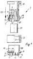
- Fig.1
- eine teilweise im Längsschnitt, teilweise in Seitenansicht gehaltene Explosionsansicht einer Ausführungsform der erfindungsgemäßen Anschlußarmatur, bei welcher eine den Anschlag bildende oder aufweisende Hülse ein Außengewinde zum Zusammenwirken mit einer demgegenüber verdrehbaren Gewindehülse hat, so daß die axiale Ausdehnung der Anschlaghülse und der Gewindehülse stufenlos verstellbar und dadurch die Gewindehülse gegen einen als Widerlager dienenden Bund zum Verspannen andrückbar ist,
- Fig.2
- die Anschlußarmatur nach Fig.1 in Vormontagestellung, das heißt nach dem Einsetzen in eine Lochung einer Wandung, jedoch vor dem Befestigen,
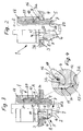
- Fig.3
- eine der Fig.2 entsprechende Darstellung nach dem Verstellen der Gewindehülse gegenüber der Anschlaghülse in axialer Richtung zur Vergrößerung der Gesamtabmessung und dadurch zur Verspannung der Anschlußarmatur in der Lochung einerseits und gegenüber einem länglichen Körper oder Kabel andererseits,
- Fig.4
- in vergrößertem Maßstab die in Fig.3 durch den Kreis A markierte Einzelheit und dabei insbesondere die Verklemmung eines an der Anschlaghülse befindlichen Stutzens an der Innenseite der Öffnung, wobei dennoch die Außenseite einer Haltezunge und eines auf dieser befindlichen Führungselementes von dem hintergriffenen Rand der Lochung beabstandet bleibt,
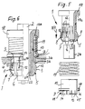
- Fig.5
- eine teilweise im Längsschnitt, teilweise in Ansicht gehaltene Explosionsdarstellung einer abgewandelten Ausführungsform der Anschlußarmatur, bei welcher die Axialbewegung zur Durchführung der Verspannung mittels einer Druckfeder zwischen Anschlaghülse und Bund oder Widerlager an der Anschlußarmatur bewirkt werden soll, sowie
- Fig.6
- die Ausführungsform gem. Fig.5 in einer der Fig.2 entsprechenden, teils im Längsschnitt, teils in Seitenansicht gehaltenen Vormontagestellung nach dem Einsetzen in eine Öffnung oder Lochung einer Wandung aber vor dem Verklemmen mit der Lochung und mit dem länglichen Körper.
- Fig. 1
- a partially in longitudinal section, partially in side view exploded view of an embodiment of the connection fitting according to the invention, in which a sleeve forming or having the stop has an external thread for cooperation with a rotatable threaded sleeve, so that the axial expansion of the stop sleeve and the threaded sleeve is continuously adjustable and thereby the threaded sleeve can be pressed against a collar serving as an abutment for tensioning,
- Fig. 2
- the connection fitting according to Figure 1 in the pre-assembly position, that is after insertion into a hole in a wall, but before fastening,
- Fig. 3
- 2 shows a representation corresponding to FIG. 2 after adjusting the threaded sleeve relative to the stop sleeve in the axial direction in order to enlarge the overall dimension and thereby to brace the connection fitting in the perforation on the one hand and with respect to an elongated body or cable on the other hand,
- Fig. 4
- on an enlarged scale, the detail marked by the circle A in FIG. 3 and in particular the jamming of a connecting piece located on the stop sleeve on the inside of the opening, the outer side of a holding tongue and a guide element located thereon nevertheless being spaced apart from the engaging edge of the perforation remains,
- Fig. 5
- a partially in longitudinal section, partially in an exploded view of a modified embodiment of the connection fitting, in which the axial movement to carry out the bracing by means of a compression spring between the stop sleeve and collar or abutment on the connection fitting is to be effected, and
- Fig. 6
- the embodiment acc. 5 in a pre-assembly position corresponding to FIG. 2, partly in longitudinal section, partly in side view, after insertion into an opening or perforation of a wall, but before jamming with the perforation and with the elongated body.
Bei der nachfolgenden Beschreibung unterschiedlicher Ausführungsbeispiele einer im ganzen mit 1 bezeichneten Anschlußarmatur erhalten hinsichtlich ihrer Funktion übereinstimmende Teile dieselben Bezugszahlen, auch wenn sie abweichend gestaltet sind.In the following description of different exemplary embodiments received a connection fitting designated as a whole the same parts in terms of their function Reference numbers, even if they are designed differently.
Die Anschlußarmatur 1 dient zum Befestigen von länglichen Körpern,
in den dargestellten Ausführungsbeispielen von Kabeln 2, aber auch
von Schläuchen, Rohren, Wellschläuchen oder dergleichen an einer
Öffnung 3, die vor allem eine Lochung oder ein Durchbruch in einer
Wandung 4 eines Gehäuses oder dergleichen sein kann. Die Anordnung
der Anschlußarmatur 1 relativ zu einer solchen Öffnung 3 und einer
Wandung 4 erkennt man in den Figuren 2 bis 4 und 6. The
In beiden Ausführungsbeispielen erkennt man insbesondere auch in
den Figuren 1 und 5, daß die Anschlußarmatur 1 einen in Einsteckrichtung
gemäß dem Pfeil Pf1 axial vorstehenden Befestigungsvorsprung
5 aufweist, der durch in axialer Richtung verlaufende Schlitze 6
in Haltezungen 7 aufgeteilt ist, an deren Außenseite radial nach
außen vorstehende Haltevorsprünge 8 angeordnet sind, die beim
Einschieben des Befestigungsvorsprunges 5 und seiner Haltezungen
7 in die Öffnung 3 hinter deren Rand 3a, diesen hintergreifend,
in die Halteposition gemäß den Figuren 2 bis 4 und 6 gelangen.In both exemplary embodiments, one can also see in particular in
Figures 1 and 5 that the connection fitting 1 one in the direction of insertion
according to arrow Pf1 axially protruding
Die Haltezungen 7 haben dabei an ihren Haltevorsprüngen 8 in ihrem
Anlagebereich, also dem Bereich, der in Gebrauchsstellung nahe dem
Rand 3a zu liegen kommt, eine sich in Einsteckrichtung gemäß dem
Pfeil Pf1 erweiternde und demgemäß in der - entgegengesetzten -
Rückzugsrichtung verjüngende Form und bilden etwa einen Konus. Dies
führt dazu, daß die Haltezungen 7 bei einer Axialbewegung der
Anschlußarmatur entgegen ihrer Einsteckrichtung, also aus ihrer
in Fig.2 und 6 dargestellten Position in eine Lage gemäß Fig.3 und
4, in radialer Richtung verformbar sind. Mit Abstand zu diesen
Haltevorsprüngen 8 ist eine einen Anschlag 9 aufweisende oder
bildende Hülse 10, im folgenden auch "Anschlaghülse 10" genannt,
angeordnet, die an dem dem hintergriffenen Rand 3a der Öffnung 3
gegenüberliegenden, in der Regel also äußeren, Öffnungsrand 3b in
Montagestellung anliegt und zur Erzeugung einer Klemmkraft zwischen
den Haltevorsprüngen 8 und dem Anschlag 9 in axialer Richtung unter
Verkleinerung des Abstandes zu den Haltevorsprüngen 8 verschiebbar
ist, woraus die radiale Verformung der die Haltevorsprünge 8
aufweisenden Haltezungen 7 in die in Fig.3 und 4 dargestellte Lage
resultiert.The holding
Die den Anschlag 9 aufweisende Hülse 10 weist dabei in beiden
Ausführungsbeispielen einen sich von dem Anschlag 9 aus axial
erstreckenden Stutzen 11 auf (Fig. 1 und 5), der in Montagestellung
an der Außenseite der Haltezungen 7 des Befestigungsvorsprunges
5 zwischen diesem und der Innenwandung der hintergriffenen Öffnung
3 verläuft und zu liegen kommt und bei einer Axialbewegung des
Befestigungsvorsprunges 5 und seiner Haltezungen 7 einen konischen
oder sich verjüngenden Bereich dieser Haltezungen 7, also den
entsprechend konisch gestalteten Haltevorsprung 8 der Haltezungen
7 beaufschlagt und dadurch zu der radialen Verformung und
Zusammendrückung bei der entsprechenden Relativbewegung dient. Es
wird also nicht der hintergriffene Lochungsrand 3a selbst unmittelbar
dazu verwendet, um die Axialbewegung des Befestigungsvorsprunges
5 entgegen der Einsteckrichtung in eine radiale Verformung der
Haltezungen 7 umzusetzen, sondern dies geschieht mit Hilfe des
Stutzens 11, so daß selbst scharfkantige oder zerklüftete oder
schartige Ränder 3a keine Beschädigungen an der Außenseite der
Haltezungen 7 und auch keine gegenseitige ungewollte Verzahnung
an dieser Stelle bewirken können. Somit wird die Axialbewegung zum
Herstellen der Verklemmung auch nicht durch einen solchen
scharfkantigen, sich eventuell in die Außenseite der Haltezunge
7 bzw. ihres Haltevorsprunges 8 eingrabenden Rand behindert. Vielmehr
schirmt der Stutzen 11 die jeweilige Haltezunge 7 gegenüber der
Öffnung 3 und insbesondere auch ihrem innenliegenden Rand 3a ab.The
Dabei wird vor allem anhand der Fig.4 deutlich, daß der Stutzen
11 durch die von ihm radial zusammendrückbaren Haltezungen 7 selbst
radial aufweitbar und in Montagestellung zumindest bereichsweise
gegen die Innenwandung der Öffnung 3 andrückbar ist. Dabei sei an
dieser Stelle erwähnt, daß der in Fig.4 teilweise sichtbare Stutzen
11 in diesem Falle noch durch ein vom Betrachter aus gesehen vor
ihm liegendes, im folgenden noch zu beschreibendes Führungselement
bzw. eine Führungsleiste 12 teilweise verdeckt ist, also über seine
gesamte axiale Erstreckung im wesentlichen eine gleichbleibende
radiale Dicke hat.It is clear above all from Figure 4 that the
Vor allem in Fig.1 und 5, aber auch in den Figuren 2, 3 und 6 erkennt
man dabei, daß in diesen Ausführungsbeispielen der an der
Anschlaghülse 10 in axialer Richtung vorspringende und in
Montagestellung in die Öffnung 3 eingreifende Stutzen 11 durch axial
verlaufende, an seiner Stirnseite offene Schlitze 13 in einzelne
Gleitzungen 14 aufgeteilt ist. Der Stutzen 11 und somit auch die
ihn bildenden Gleitzungen 14 sind dabei außenseitig vorsprungfrei,
also im wesentlichen glatt und können entsprechend leicht zusammen
mit der gesamten Anschlußarmatur 1 in die Öffnung 3 eingeführt
werden. Der Stutzen 11 hat dabei in Vormontagestellung oder
entspannter Lage gemäß den Figuren 1 und 5 eine etwa zylindrische
Form, könnte also innerhalb eines gedachten Hüllzylinders verlaufen.
Somit ist seine Außenseite weitgehend an die Innenseite einer Öffnung
3 angepaßt, die in der Regel ebenfalls zylindrisch gestaltet ist.
In Gebrauchsstellung hat er dabei gemäß den Figuren 2 bis 4 und
6 sogar gegenüber der Innenwand der Öffnung 3 noch etwas Luft oder
Spiel.Especially in Figures 1 and 5, but also in Figures 2, 3 and 6
one that the in these embodiments of the
Gemäß Fig.2 und 5 reicht der an der Anschlaghülse 10 befindliche
Stutzen 11 schon in Ausgangsstellung der Klemmbewegung bis an die
Haltevorsprünge 8 heran, so daß die relative Axialbewegung sofort
auch in eine entsprechende radiale Verschwenkung der die Haltevorsprünge
8 aufweisenden Haltezungen 7 umgesetzt wird. Darüber hinaus
weist er eine mit einer Schrägfläche dieser Haltevorsprünge 8
zusammenwirkende Einführschräge 15 auf, die in Fig.4 durch eine
unterbrochene Linie hinter der schon erwähnten Führungsleiste 12
und im übrigen vor allem in den Figuren 1 und 5 sichtbar gemacht
ist. Dies führt zu einer gleichmäßigen Einführung der Haltevorsprünge
8 und damit der Haltezungen 7 in den Stutzen 11, was die gegenseitige
axiale Bewegung zur Herbeiführung der radialen Verschwenkung der
Haltezungen 7 gemäß dem Pfeil Pf2 in Fig.3 erleichtert, selbst wenn
der Schrägungswinkel an der Außenseite der Haltevorsprünge 8 von
dem der Einführschräge 15 in der in Fig.4 erkennbaren Weise abweicht,
also zwischen der Einführschräge 15 und der Außenseite der
Haltevorsprünge 8 zumindest in Gebrauchsstellung noch ein Winkelraum
verbleibt.According to FIGS. 2 and 5, the one located on the
Die axiale Abmessung des Stutzens 11, also die Abmessung von dem
Anschlag 9 bis zum freien stirnseitigen Rand des Stutzens 11, ist
dabei im Ausführungsbeispiel geringer als die axiale Ausdehnung
der von dem Befestigungsvorsprung 5 durchsetzten Öffnung 3, also
etwas geringer als die Dicke der die Öffnung 3 aufweisenden Wandung
4 und entspricht somit nur einem Bruchteil dieser Wanddicke bzw.
axialen Ausdehnung der Öffnung 3. Dabei übertrifft diese axiale
Ausdehnung des Stutzens 11 allerdings die Hälfte der axialen
Ausdehnung der Öffnung 3, so daß der größte Teil der Öffnung 3 durch
den Stutzen 11 und dessen Gleitzungen 14 in Gebrauchsstellung
ausgekleidet wird. Wenn dabei der Bereich des hintergriffenen Randes
3a der Öffnung 3 von dem Stutzen 11 freigelassen, also nicht
ausgekleidet ist, hat dies dennoch keinen Einfluß darauf, daß die
Außenseite der Haltevorsprünge 8 und auch die Führungselemente oder
Führungsleisten 12 von diesem hintergriffenen Rand 3a auf - geringfügigen
- Abstand gehalten werden. Die radiale Dicke des Stutzens
11 bzw. der Gleitzungen 14 und die Schrägung der Außenseite der
Haltevorsprünge 8 sind so abgestimmt, daß selbst in der Montagestellung
gemäß Fig.3 und 4 keine Berührung zwischen dem
hintergriffenen Rand 3a und den Haltevorsprüngen 8 und den
Führungsleisten 12 auftritt, also trotz der in axialer Richtung
wirkenden Kraft keine Einprägungen oder Beschädigungen durch den
unter Umständen scharfkantigen Rand 3a verursacht werden können.The axial dimension of the
Selbstverständlich könnte allerdings der Stutzen 11 auch die gesamte
Öffnung 3 innenseitig auskleiden oder eventuell sogar noch etwas
über den Rand 3a überstehen. Dazu würde es zum Beispiel kommen,
wenn die Anschlußarmatur 1 gemäß den Figuren 1 bis 6 in der
dargestellten Abmessung an einer Öffnung 3 angebracht würde, die
eine Wand 4 geringerer Dicke durchsetzt.Of course, the
Die Zahl der Schlitze 13 in dem Stutzen 11 und die Zahl der Schlitze
6 sowie der Haltezungen 7 an dem Befestigungsvorsprung 5 sind im
Ausführungsbeispiel gleich. Dabei sind jedoch gemäß Fig.2, 3 und
6 die Schlitze 13 des Stutzens 11 und die Schlitze 6 des Befestigungsvorsprunges
5 in Montagestellung in Umfangsrichtung
gegeneinander - um eine halbe Teilung - versetzt. Somit wird ein
Schlitz 6 an dem Befestigungsvorsprung 5 zumindest innerhalb der
Öffnung 3 durch eine Gleitzunge 14 außenseitig überdeckt, während
umgekehrt ein Schlitz 13 des Stutzens 11 innenseitig von einer
Haltezunge 7 zumindest über einen ersten axialen Teilbereich
überdeckt wird.The number of
Dadurch ist eine weitere zweckmäßige Ausgestaltung möglich, die
in beiden Ausführungsbeispielen vorgesehen ist und darin besteht,
daß an den Befestigungsvorsprüngen 8 und somit den Außenseiten der
Haltezungen 7 an deren dem Rand 3a der Öffnung 3 zugewandten
Schrägfläche die schon erwähnten Führungselemente oder Führungsleisten
12 außenseitig angeordnet sein können, die in Gebrauchsstellung
in die Schlitze 13 des Stutzens 11 passen und bereichsweise
eingreifen und dadurch in Drehrichtung Formschluß herstellen. Dadurch
wird erreicht, daß beim Verspannen und Verklemmen der Anschlußarmatur
1 durch das Andrücken des Stutzens 11 und seiner Gleitzungen
14 im Inneren der Öffnung 3 nicht nur dieser, sondern auch die
gesamte Anschlußarmatur 1 unverdrehbar gemacht wird. Je stärker
die Verklemmung wird, um so weniger kann die gesamte Anschlußarmatur
1 verdreht werden, weil die Anschlaghülse 10 über den Stutzen 11
in der Öffnung 3 festgeklemmt und die Haltezungen 7 mit ihren
Haltevorsprüngen 8 nicht nur innenseitig in dem Stutzen 11 an den
Gleitzungen 14 ihrerseits reibschlüssig, sondern zusätzlich über
die Führungselemente 12 formschlüssig gekuppelt wird.A further expedient embodiment is thereby possible
is provided in both exemplary embodiments and consists in
that on the
Zusätzlich ist in den Anschlag 9, von welchem der Stutzen 11 ausgeht,
mit radialem Abstand zu diesem Stutzen 9 ein elastischer Ring oder
Dichtring, im Ausführungsbeispiel ein O-Ring 16 angeordnet, der
mit einem Teil seines Querschnittes in eine Ringnut 17 oder ähnliche
Vertiefung eingefügt ist und beim Verklemmen der Anschlußarmatur
1 etwas zusammengedrückt werden kann, dadurch aber gleichzeitig
auch die Reibung zwischen dem Anschlag 9 und der Wandung 4
vergrößert. Dies trägt also zur Sicherung gegen Verdrehen der
gesamten Anschlußarmatur 1 bei, so daß diese auch Kräfte oder Momente
in Drehrichtung aufnehmen kann, die beispielsweise bei der
Ausführungsform gemäß den Figuren 1 bis 3 beim Anziehen eines
Gewindes zum Verspannen und Verklemen auftreten können, was
nachfolgend noch näher beschrieben wird.In addition, in the
Dabei erfolgt diese Festlegung auch in Drehrichtung, obwohl der
dem Anschlag 9 abgewandte freie Rand des Stutzens 11 und der ihn
bildenden Gleitzungen 14 die Haltezungen 7 und auch die Führungsleisten
12 außenseitig derart beaufschlagen und in radialer Richtung
festlegen, daß deren Außenumfang im Bereich des zu hintergreifenden
oder hintergriffenen Randes 3a der Öffnung 3 im Ausführungsbeispiel
kleiner, gegebenenfalls aber auch gerade noch gleich dem Umfang
dieses Randes 3a ist und obwohl der Schrägungswinkel an der
Außenseite der Haltezungen 7 und Haltevorsprünge 8 im Bereich des
Stutzens 11 und von dessen Einführschräge 15 einen derartigen Winkel
haben, daß bei der Axialbewegung des Befestigungsvorsprunges 5 in
Richtung auf die Öffnung 3 hin, also entgegen der durch den Pfeil
Pf1 angedeuteten Einsteckrichtung, die radiale Zusammendrückung
der Haltezungen 7 so groß ist, daß sie weiterhin an dem hintergriffenen
Rand 3a der Öffnung 3 berührungsfrei oder zumindest im
wesentlichen reibungsfrei bleiben.This determination is also made in the direction of rotation, although the
the free edge of the
Die Reibung wird vielmehr innerhalb der Öffnung 3 zwischen dieser
und der Außenseite des Stutzens 11 einerseits und zwischen der
Innenseite des Stutzens 11 und der Außenseite der Haltezungen 7
bzw. der Haltevorsprünge 8 erzeugt, wobei zusätzlich noch eine
Verdrehsicherung mit den Führungselementen 12 zur Verfügung steht.
Somit erfolgt eine sichere und stabile Festlegung an der Öffnung
3, obwohl in scheinbar widersprüchlicher Weise die die Öffnung 3
an deren innenliegendem Rand 3a hintergreifenden Bereiche der
Haltezungen 7 den hintergriffenen Rand 3a nicht oder kaum berühren.Rather, the friction is within the
Um die Axialkraft entgegen der Einsteckrichtung, also entgegengesetzt
zu dem Pfeil Pf1 an der Anschlußarmatur aufzubringen, weist sie
an ihrem dem Befestigungsvorsprung 5 abgewandten Bereich oder Rand
in beiden Ausführungsbeispielen ein radial vorstehendes Widerlager
in Form eines ringförmigen Bundes 18 auf, der ein Widerlager für
ein jeweils etwas unterschiedlich gestaltetes Verschiebe- oder
Spannelement bildet, welches zwischen diesem Bund 18 und dem Anschlag
9 der Anschlaghülse 10 angeordnet ist und den Anschlag 9 und diesen
Bund 18 in axialer Richtung auseinanderdrückt. Wird durch ein solches
noch näher zu erläuterndes Verschiebeelement der Abstand
zwischen dem Bund 18 und dem Anschlag 9 vergrößert, bedeutet dies
automatisch eine Verringerung des Abstandes des Anschlages 9 von
den Haltevorsprüngen 8 der Haltezungen 7 des Befestigungsvorsprunges
5 und damit deren Verklemmung und radiale Verschwenkung, weil dann
der freie Rand des Stutzens 11 weiter auf die schrägen Haltevorsprünge
8 geschoben bzw. umgekehrt diese Haltevorsprünge 8 in den
Stutzen 11 hineingezogen und aufgrund ihrer außenseitigen Schräge
gleichzeitig radial nach innen verschwenkt werden.To the axial force against the direction of insertion, that is opposite
apply to the arrow Pf1 on the connection fitting, it points
at its area or edge facing away from the
Das Verschiebe- oder Spannelement zwischen Bund 18 und Anschlag
9 ist im Ausführungsbeispiel gemäß den Figuren 5 und 6 eine Feder
und zwar eine Druckfeder 19, die in zusammengedrücktem Zustand das
Einführen des Befestigungsvorsprunges 5 in die Öffnung 3 erlaubt,
weil der Abstand zwischen Anschlag 9 und den Haltevorsprüngen 8
noch entsprechend groß ist, während das Entspannen dieser Druckfeder
19 in dem Sinne wirkt, daß der Anschlag 9 und der Bund 18
auseinandergedrückt werden, so daß nach einem Freigeben der
Federkraft der Druckfeder 19 die vorstehend schon beschriebene
Verspannung und Verklemmung der Anschlußarmatur 1 erfolgt.The sliding or tensioning element between
Fig.6 zeigt dabei die noch nicht verspannte und verklemmte Anordnung,
bei welcher die Druckfeder 19 ihrerseits noch zusammengedrückt ist,
wobei leicht vorstellbar ist, daß bei einer entsprechenden Freigabe
der Druckfeder, wenn diese also in eine Form entspannt wird, wie
man sie in Fig.5 erkennt, die Verspannung und Verklemmung in zu
Fig.3 vergleichbarer Weise erfolgt.6 shows the not yet braced and jammed arrangement,
in which the
Fig.6 zeigt also einen Zustand, bei welchem der Benutzer beispielsweise
an dem Bund 18 angreift und diesen in Richtung auf die Wandung
4 niedergedrückt hält. Läßt er ihn los, wird die Anschlußarmatur
1 durch die Druckfeder 19 in axialer Richtung entgegen der durch
den Pfeil Pf1 angedeuteten Einsteckrichtung zurückbewegt und dadurch
an ihrem Befestigungsvorsprung 5 verklemmt, wodurch gleichzeitig
die Haltezungen 7 analog der Anordnung der Fig.3 radial gemäß dem
Pfeil Pf2 nach innen verschwenkt und gegen den länglichen Körper,
also das Kabel 2 gedrückt oder sogar in dessen Oberfläche etwas
eingedrückt werden.6 therefore shows a state in which the user, for example
engages the
Im Ausführungsbeispiel gemäß den Figuren 1 bis 3 ist das Spannelement
eine mit einem Außengewinde 20 an der Anschlaghülse 10 zusammenwirkende,
zum Spannen von dem Anschlag 9 weg verdrehbare, ein
Innengewinde 21 aufweisende Gewindehülse 22. Während diese Anordnung
in Fig.2 in schon in die Öffnung 3 eingesetzter, aber noch
unverspannter Lage dargestellt ist, zeigt Figur 3, wie die
Gewindehülse 22 durch einige Umdrehungen aufgrund der zusammenwirkenden
Gewinde 20 und 21 in axialer Richtung so verstellt ist,
daß die aus dieser Gewindehülse 22 und der Anschlaghülse 10
bestehende Einheit eine größere axiale Länge erhält, was dazu führt,
daß der als Widerlager dienende Bund 18 einen größeren Abstand von
der Außenseite der Wandung 4 erhält. Dies kann nur dadurch
ausgeglichen werden, daß - wie beim Ausführungsbeispiel gemäß den
Figuren 5 und 6 - der Befestigungsvorsprung 5 mit seinen Haltezungen
7 und den daran vorgesehenen, außenseitig schrägen Haltevorsprüngen
8 wieder in die Öffnung 3 und damit in den Stutzen 11 der
Anschlaghülse 10 hineingezogen wird, was aufgrund der Abmessungen
und der Schrägflächen zu der schon mehrfach erwähnten radialen
Verschwenkung der Haltezungen 7 in Richtung des Pfeiles Pf2 und
gegen die Oberfläche des Kabels 2 führt.In the embodiment according to Figures 1 to 3 is the clamping element
a cooperating with an
Wenn dabei - in beiden Ausführungsbeispielen - die Anschlußarmatur
1 aus einem elastischen Werkstoff, insbesondere Kunststoff, besteht,
kann bei umgekehrter Bewegung der beteiligten Elemente und Teile
die Anschlußarmatur 1 auch wieder gelöst werden, weil bei einem
Verkürzen des Abstandes zwischen Anschlag 9 und Bund 18 dann die
gesamte Anschlußarmatur 1 auch wieder etwas in Richtung des Pfeiles
Pf1 bewegt werden kann, so daß die Haltezungen 7 aufgrund ihrer
Elastizität wieder von dem Kabel 2 wegverschwenkt werden, so daß
es herausgezogen und danach auch die gesamte Anschlußarmatur 1 wieder
aus der Öffnung 3 zurückgezogen werden können.If - in both embodiments - the connection fitting
1 consists of an elastic material, in particular plastic,
can with reverse movement of the elements and parts involved
the connection fitting 1 can also be solved again because at one
Shorten the distance between the
Dabei bestehen der Anschlagbund 18 und der Befestigungsvorsprung
5 mit den Haltezungen 7 und den Haltevorsprüngen 8 sowie auch den
Führungsleisten 12 in beiden Ausführungsbeispielen einstückig aus
demselben Werkstoff, insbesondere aus Kunststoff.There are the
Der als Widerlager dienende Bund 18 ist in den beiden Ausführungsbeispielen
etwas unterschiedlich gestaltet. Zum Erfassen des einen
Randes oder Endes der Druckfeder 19 hat der Bund 18 des Ausführungsbeispieles
nach Fig.5 und 6 eine Ringnut 18a, während er im
Ausführungsbeispiel gemäß 1 bis 3 radial verläuft und eben und glatt
ist, so daß die Gewindehülse 22 gegenüber diesem Bund 18 gut verdreht
werden kann, wenn die Spannbewegung oder auch die Lösebewegung
durchgeführt wird.The
Es sei noch erwähnt, daß bei beiden Ausführungsformen der
Befestigungsvorsprung 5 und damit die Haltezungen 7 stirnseitig
nach innen greifende Klauen 23 oder ähnliche Halteelemente zum
besseren Erfassen des länglichen Körpers oder Kabels 2 und
gleichzeitig zum Abstützen einer innenliegenden Dichtung, im
Ausführungsbeispiel einer Dichtungsmanschette 24 aufweisen. Somit
kann diese Dichtung 24 innenseitig festgelegt und mit an das Kabel
2 angedrückt werden, bleibt aber auch in entspannter Lage und
Vormontagestellung unverlierbar und ferner können sich die erwähnten
Klauen 23 etwas in eine elastische Oberfläche eines Kabels 2,
Schlauches oder auch in die Wellentäler eines Wellschlauches
eingraben oder einfügen.It should also be mentioned that in both embodiments the
Die Anschlußarmatur 1 dient zum Befestigen von länglichen Körpern,
beispielsweise von Kabeln 2, Schläuchen, Rohren, Wellschläuchen
oder dergleichen, an einer Öffnung 3, insbesondere auch zum
Hindurchführen durch eine solche Öffnung 3 unter gleichzeitiger
Festlegung, wobei es sich bei der Öffnung 3 um eine Lochung, eine
Bohrung oder einen sonstigen Durchbruch in einer Wandung 4, zum
Beispiel eines Gehäuses, handeln kann. Die Anschlußarmatur 1 ist
dabei als Steckarmatur ausgebildet, das heißt durch axiales
Einschieben in die Öffnung 3 wird sie bereits an dieser fixiert.
Sie weist dazu einen durch axiale Schlitze in Haltezungen
unterteilten Befestigungsvorsprung 5 auf, der außenseitig radial
vorstehende Haltevorsprünge 8 trägt, die beim Einschieben des
Befestigungsvorsprunges 5 in die Öffnung 3 hinter deren Rand 3a
gelangen, wobei sie bei diesem Einschieben etwas radial nach innen
ausweichen und nach dem Hindurchstecken sich selbsttätig wieder
radial nach außen bewegen. Durch eine Axialbewegung der Anschlußarmatur
1 entgegen ihrer Einsteckrichtung können die Haltezungen
7 wiederum in radialer Richtung gegen den festzulegenden länglichen
Körper oder ein Kabel 2 hin verformt und an diesem angeklemmt werden.
Dabei ist an der Außenseite der Öffnung 3 ein Anschlag 9 vorgesehen,
womit die Anschlußarmatur 1 außenseitig abgestützt wird. Die den
Anschlag 9 aufweisende Hülse hat einen sich axial in die Öffnung
3 erstreckenden Stutzen 11, der in Montagestellung an einem
Teilbereich der Außenseite der Haltezungen 7 des Befestigungsvorsprunges
5 angreift und bei einer Axialbewegung des Befestigungsvorsprunges
5 und seiner Haltezungen 7 einen konischen oder sich
verjüngenden Bereich dieser Haltezungen 7 außenseitig derart
beaufschlagt, daß die Haltezungen 7 in radialer Richtung zusammengedrückt
werden, so daß eine Berührung der Haltezungen 7 mit dem
hintergriffenen Rand 3a vermieden oder allenfalls mit einer erheblich
geringeren Kraft erfolgt, als sie zum radialen Verformen der
Haltezungen 7 aufgebracht wird.The
Claims (15)
Applications Claiming Priority (2)
| Application Number | Priority Date | Filing Date | Title |
|---|---|---|---|
| DE19828059A DE19828059C2 (en) | 1998-06-24 | 1998-06-24 | Connection fitting with a fastening projection divided by slots in retaining tongues |
| DE19828059 | 1998-06-24 |
Publications (3)
| Publication Number | Publication Date |
|---|---|
| EP0967701A2 true EP0967701A2 (en) | 1999-12-29 |
| EP0967701A3 EP0967701A3 (en) | 2000-02-23 |
| EP0967701B1 EP0967701B1 (en) | 2006-12-27 |
Family
ID=7871825
Family Applications (1)
| Application Number | Title | Priority Date | Filing Date |
|---|---|---|---|
| EP99106807A Expired - Lifetime EP0967701B1 (en) | 1998-06-24 | 1999-04-06 | Connection device with fastening protusion divided by slots in holders |
Country Status (4)
| Country | Link |
|---|---|
| US (1) | US6394690B1 (en) |
| EP (1) | EP0967701B1 (en) |
| DE (2) | DE19828059C2 (en) |
| ES (1) | ES2280108T3 (en) |
Cited By (8)
| Publication number | Priority date | Publication date | Assignee | Title |
|---|---|---|---|---|
| EP1152180A2 (en) | 2000-05-05 | 2001-11-07 | Reiku GmbH | Device for fixing a corrugated pipe into a wall opening |
| EP1172596A1 (en) * | 2000-07-12 | 2002-01-16 | Anton Hummel Verwaltungs GmbH | Connecting device with collet for elongated bodies |
| CN1303735C (en) * | 2000-07-01 | 2007-03-07 | 安东-胡梅尔管理有限公司 | Connecting fitting with elastic ring as stop |
| WO2009074202A1 (en) * | 2007-12-13 | 2009-06-18 | A. Raymond Et Cie | Plug-in piece for a fluid line coupling and fluid line coupling |
| FR2944851A1 (en) * | 2009-04-28 | 2010-10-29 | Somatherm | SYSTEM FOR FASTENING A CONNECTION FOR CONDUCTING FLUID TRANSPORT TO A PARTITION. |
| CN101079538B (en) * | 2006-05-25 | 2011-02-09 | 拉普工程公司 | Cable bushing |
| CH702794A1 (en) * | 2010-03-03 | 2011-09-15 | Nussbaum & Co Ag R | Connecting piece for coupler of tube connector of armature for metal tubes of fluid-guided line system, particularly for drinking water, has one tubular part, which is connected with another tubular part |
| US10094503B2 (en) * | 2016-01-20 | 2018-10-09 | Brian John Kelk | Sewer pipe fitting assembly |
Families Citing this family (24)
| Publication number | Priority date | Publication date | Assignee | Title |
|---|---|---|---|---|
| US20040228704A1 (en) * | 2001-04-30 | 2004-11-18 | Dov Rotshtain | Fastener system |
| DE20211347U1 (en) * | 2002-07-27 | 2002-09-26 | Hummel Anton Verwaltung | End fittings |
| US7024824B1 (en) | 2003-09-04 | 2006-04-11 | Felix Widlacki | Entry port |
| DE202005003812U1 (en) * | 2005-03-07 | 2006-07-20 | BÖHL, Harald | Clamping sleeve and clamp connection |
| US7857360B2 (en) * | 2006-04-26 | 2010-12-28 | Parker-Hannifin Corporation | Snap-in-place valved coupler |
| DE102007053443A1 (en) | 2007-11-07 | 2009-06-10 | Amazonen-Werke H. Dreyer Gmbh & Co. Kg | Connection fitting for e.g. cable, has clamping ring placed such that inner diameter of opening corresponds to outer diameter of oblong body and outer diameter of tongues is larger in area of bulge than inner diameter of area of ring |
| DE202007017765U1 (en) * | 2007-12-20 | 2008-03-06 | Anton Hummel Verwaltungs-Gmbh | End fittings |
| GB2465435B (en) * | 2008-11-25 | 2011-02-23 | Saint Gobain Performance Plast | Process control of tolerance rings |
| FR2941029B1 (en) * | 2009-01-14 | 2011-05-20 | Legris Sa | DEVICE FOR ANCHORING AN ELEMENT IN AN OPENING OF A WALL AND CONNECTING EQUIPPED WITH SUCH A DEVICE |
| DE102009021700A1 (en) | 2009-05-17 | 2010-11-18 | Hidde, Axel, Dipl.-Ing. | Universal quick-release fitting |
| CN102157908B (en) * | 2010-02-12 | 2014-06-25 | 通用汽车环球科技运作公司 | Adjustable conduit end fitting for cable |
| DE102010032983A1 (en) * | 2010-07-31 | 2012-02-02 | Vag-Armaturen Gmbh | connector |
| CN104823092B (en) * | 2012-07-10 | 2017-05-17 | 3M创新有限公司 | Wireless connector with a hollow telescopic waveguide |
| GB2507715B (en) * | 2012-09-04 | 2014-12-03 | Sidi Mohamed Ilias Berhili | Electrical back box installation system |
| DE102013218733A1 (en) * | 2013-09-18 | 2015-03-19 | Bimed Teknik A.S. | Cable guiding device |
| JP6331137B2 (en) * | 2014-07-18 | 2018-05-30 | 前澤化成工業株式会社 | Branch joint |
| EP3101326B1 (en) * | 2015-06-03 | 2017-05-03 | Axis AB | Mounting arrangement for mounting a device, and methods for mounting and dismounting a device |
| US10697573B2 (en) * | 2017-06-27 | 2020-06-30 | Kenny Bassett | Plumbing fitting assembly for transverse hole in structure |
| FR3074730A1 (en) * | 2017-12-11 | 2019-06-14 | Psa Automobiles Sa | DEVICE FOR PASSING AT LEAST ONE DRIVING |
| IT201800001835U1 (en) * | 2018-02-02 | 2019-08-02 | Valve for cylinder with gas under pressure | |
| DE102018109998A1 (en) * | 2018-04-25 | 2019-10-31 | Pipe-Aqua-Tec Gmbh & Co.Kg | Pipe connection system and method for producing a pipe connection |
| CN109586221B (en) * | 2018-11-14 | 2020-05-22 | 陕西中昌科技有限公司 | Electric cable wall-penetrating protection tube |
| CN109586218B (en) * | 2018-11-14 | 2020-05-08 | 河北鑫鹏通信设备有限公司 | Power cable protective sleeve with waterproof structure |
| CN109296836A (en) * | 2018-11-30 | 2019-02-01 | 常州常发制冷科技有限公司 | Screw-type sealed fitting and its installation method |
Citations (5)
| Publication number | Priority date | Publication date | Assignee | Title |
|---|---|---|---|---|
| GB2126803A (en) * | 1982-08-25 | 1984-03-28 | Franz Lackinger | Tension resisting electrical cable gland |
| EP0206896A1 (en) * | 1985-06-17 | 1986-12-30 | CAPRI-CODEC S.A.:Société anonyme dite | Modular stuffing box suitable for passing a cylindrical conduit through a wall |
| DE4225263C1 (en) * | 1992-07-31 | 1994-02-17 | Lapp U I Gmbh & Co Kg | Cable wall mounting clamp - has clamping cage and collet tightened by rotation of the cap nut to secure and clamp the cable through wall. |
| WO1998015764A1 (en) * | 1996-10-08 | 1998-04-16 | Dover Corporation | Improved bulkhead fitting for underground sump |
| DE29701321U1 (en) * | 1997-01-28 | 1998-05-20 | Kleinhuis Hermann Gmbh | Screw connection |
Family Cites Families (11)
| Publication number | Priority date | Publication date | Assignee | Title |
|---|---|---|---|---|
| US1246102A (en) * | 1915-07-24 | 1917-11-13 | Winner Mfg Co Inc | Junction-box connector. |
| US1717389A (en) * | 1922-08-25 | 1929-06-18 | Kipnis Abraham | Coupling means for electrical conduits and the like |
| US1745941A (en) * | 1928-04-04 | 1930-02-04 | Erie Malleable Iron Co | Conduit fitting |
| US1885581A (en) * | 1929-10-24 | 1932-11-01 | Erie Malleable Iron Co | Conduit fitting |
| US1902229A (en) * | 1931-07-30 | 1933-03-21 | Appleton Electric Co | Pipe connecter |
| US2038290A (en) * | 1935-01-28 | 1936-04-21 | John W Hooley | Electrical fixture |
| US2514504A (en) * | 1947-04-19 | 1950-07-11 | Pullman Standard Car Mfg Co | Pipe clamp |
| US3415549A (en) * | 1965-09-23 | 1968-12-10 | Newton L. Chatham | Cable housing anchoring unit |
| DE6944941U (en) * | 1969-11-14 | 1970-03-12 | Depol Deutsches Gummi Regeneri | ONE-PIECE, PUSH-IN AND SCREW-FASTENED CABLE STRAIN RELIEF MADE OF THERMAL OR. DUROPLASTIC PLASTIC |
| JP3383884B2 (en) * | 1992-08-07 | 2003-03-10 | ニッタ・ムアー株式会社 | Component mounting mechanism |
| DE19804719C1 (en) * | 1998-02-06 | 1999-04-08 | Hummel Anton Verwaltung | Connecting fitting with axial protruding fixing projection fixing body e.g. hose |
-
1998
- 1998-06-24 DE DE19828059A patent/DE19828059C2/en not_active Expired - Fee Related
-
1999
- 1999-04-06 DE DE59914085T patent/DE59914085D1/en not_active Expired - Lifetime
- 1999-04-06 EP EP99106807A patent/EP0967701B1/en not_active Expired - Lifetime
- 1999-04-06 ES ES99106807T patent/ES2280108T3/en not_active Expired - Lifetime
- 1999-06-01 US US09/323,732 patent/US6394690B1/en not_active Expired - Lifetime
Patent Citations (5)
| Publication number | Priority date | Publication date | Assignee | Title |
|---|---|---|---|---|
| GB2126803A (en) * | 1982-08-25 | 1984-03-28 | Franz Lackinger | Tension resisting electrical cable gland |
| EP0206896A1 (en) * | 1985-06-17 | 1986-12-30 | CAPRI-CODEC S.A.:Société anonyme dite | Modular stuffing box suitable for passing a cylindrical conduit through a wall |
| DE4225263C1 (en) * | 1992-07-31 | 1994-02-17 | Lapp U I Gmbh & Co Kg | Cable wall mounting clamp - has clamping cage and collet tightened by rotation of the cap nut to secure and clamp the cable through wall. |
| WO1998015764A1 (en) * | 1996-10-08 | 1998-04-16 | Dover Corporation | Improved bulkhead fitting for underground sump |
| DE29701321U1 (en) * | 1997-01-28 | 1998-05-20 | Kleinhuis Hermann Gmbh | Screw connection |
Cited By (11)
| Publication number | Priority date | Publication date | Assignee | Title |
|---|---|---|---|---|
| EP1152180A2 (en) | 2000-05-05 | 2001-11-07 | Reiku GmbH | Device for fixing a corrugated pipe into a wall opening |
| EP1152180B1 (en) * | 2000-05-05 | 2005-08-03 | Reiku GmbH | Device for fixing a corrugated pipe into a wall opening |
| CN1303735C (en) * | 2000-07-01 | 2007-03-07 | 安东-胡梅尔管理有限公司 | Connecting fitting with elastic ring as stop |
| EP1172596A1 (en) * | 2000-07-12 | 2002-01-16 | Anton Hummel Verwaltungs GmbH | Connecting device with collet for elongated bodies |
| US6511099B2 (en) | 2000-07-12 | 2003-01-28 | Anton Hummel Verwaltungs Gmbh | Connection fitting with clamping collet for elongated bodies |
| CN101079538B (en) * | 2006-05-25 | 2011-02-09 | 拉普工程公司 | Cable bushing |
| WO2009074202A1 (en) * | 2007-12-13 | 2009-06-18 | A. Raymond Et Cie | Plug-in piece for a fluid line coupling and fluid line coupling |
| FR2944851A1 (en) * | 2009-04-28 | 2010-10-29 | Somatherm | SYSTEM FOR FASTENING A CONNECTION FOR CONDUCTING FLUID TRANSPORT TO A PARTITION. |
| WO2010125300A1 (en) * | 2009-04-28 | 2010-11-04 | Somatherm | System for attaching a connector for a fluid transport pipe on a wall |
| CH702794A1 (en) * | 2010-03-03 | 2011-09-15 | Nussbaum & Co Ag R | Connecting piece for coupler of tube connector of armature for metal tubes of fluid-guided line system, particularly for drinking water, has one tubular part, which is connected with another tubular part |
| US10094503B2 (en) * | 2016-01-20 | 2018-10-09 | Brian John Kelk | Sewer pipe fitting assembly |
Also Published As
| Publication number | Publication date |
|---|---|
| DE19828059C2 (en) | 2001-04-26 |
| US6394690B1 (en) | 2002-05-28 |
| DE19828059A1 (en) | 2000-01-05 |
| DE59914085D1 (en) | 2007-02-08 |
| EP0967701A3 (en) | 2000-02-23 |
| EP0967701B1 (en) | 2006-12-27 |
| ES2280108T3 (en) | 2007-09-01 |
Similar Documents
| Publication | Publication Date | Title |
|---|---|---|
| DE19828059C2 (en) | Connection fitting with a fastening projection divided by slots in retaining tongues | |
| EP0943856B1 (en) | Connecting device with mounting protrusion | |
| EP2406121B1 (en) | Tie rod for motor vehicles | |
| DE3424675C2 (en) | Hose coupling | |
| DE10032010C1 (en) | Connection fitting for a pipe etc. through a housing wall has a division near the angled support surface for the limit ring to allow for large wall thickness differences | |
| DE3815168C2 (en) | ||
| DE4304241C2 (en) | Plug connection for pipes, hoses or round bodies | |
| EP1065426A2 (en) | Connecting device for the fastening of elongated bodies | |
| EP0059877A1 (en) | Coupling for delivery piping | |
| DE102005031871B3 (en) | Connecting device for corrugated hose has holding device with connecting device able to be engaged in two stages | |
| DE2610200C3 (en) | Fitting for the detachable connection of two components, in particular panel-shaped components for furniture | |
| EP0610538A1 (en) | Quick connection for pipes, hoses and the like | |
| EP0932789A1 (en) | Pipe connection and combination of a connection and a detaching tool | |
| DE4430114C2 (en) | Connector for a plastic hose of a bathroom hand shower | |
| EP2712413A2 (en) | Connecting device for connecting a fluid line | |
| EP0964493A2 (en) | Angular cable entry with a disconnecting point between the two legs | |
| WO2020200776A1 (en) | Multipart adjustment element for a tolerance compensation assembly | |
| DE2635970C3 (en) | Loosening lock for a nut screwed onto a threaded bolt | |
| DE1600466B2 (en) | FITTED PIPE FOR PLASTIC PIPES | |
| DE4104009C2 (en) | Coupling piece. | |
| EP0825375B1 (en) | Hose screw connection | |
| AT406601B (en) | FASTENING ARRANGEMENT | |
| DE10058967B4 (en) | Connecting device for fluid lines | |
| DE10214997A1 (en) | Hydraulic connecting device for connecting hose connector to nut has circumferential retaining slot in hose connector, and nut has inner radial chamber to accommodate spring ring and with areas of differing depths | |
| DE3631026C2 (en) |
Legal Events
| Date | Code | Title | Description |
|---|---|---|---|
| PUAI | Public reference made under article 153(3) epc to a published international application that has entered the european phase |
Free format text: ORIGINAL CODE: 0009012 |
|
| AK | Designated contracting states |
Kind code of ref document: A2 Designated state(s): CH DE ES FR GB IT LI SE |
|
| AX | Request for extension of the european patent |
Free format text: AL;LT;LV;MK;RO;SI |
|
| PUAL | Search report despatched |
Free format text: ORIGINAL CODE: 0009013 |
|
| AK | Designated contracting states |
Kind code of ref document: A3 Designated state(s): AT BE CH CY DE DK ES FI FR GB GR IE IT LI LU MC NL PT SE |
|
| AX | Request for extension of the european patent |
Free format text: AL;LT;LV;MK;RO;SI |
|
| RIC1 | Information provided on ipc code assigned before grant |
Free format text: 7H 02G 3/06 A, 7H 02G 15/04 B |
|
| 17P | Request for examination filed |
Effective date: 20000201 |
|
| AKX | Designation fees paid |
Free format text: CH DE ES FR GB IT LI SE |
|
| GRAP | Despatch of communication of intention to grant a patent |
Free format text: ORIGINAL CODE: EPIDOSNIGR1 |
|
| GRAS | Grant fee paid |
Free format text: ORIGINAL CODE: EPIDOSNIGR3 |
|
| GRAA | (expected) grant |
Free format text: ORIGINAL CODE: 0009210 |
|
| AK | Designated contracting states |
Kind code of ref document: B1 Designated state(s): CH DE ES FR GB IT LI SE |
|
| REG | Reference to a national code |
Ref country code: GB Ref legal event code: FG4D Free format text: NOT ENGLISH |
|
| REF | Corresponds to: |
Ref document number: 59914085 Country of ref document: DE Date of ref document: 20070208 Kind code of ref document: P |
|
| REG | Reference to a national code |
Ref country code: CH Ref legal event code: NV Representative=s name: HANS RUDOLF GACHNANG PATENTANWALT |
|
| REG | Reference to a national code |
Ref country code: SE Ref legal event code: TRGR |
|
| GBT | Gb: translation of ep patent filed (gb section 77(6)(a)/1977) |
Effective date: 20070404 |
|
| ET | Fr: translation filed | ||
| REG | Reference to a national code |
Ref country code: ES Ref legal event code: FG2A Ref document number: 2280108 Country of ref document: ES Kind code of ref document: T3 |
|
| PLBE | No opposition filed within time limit |
Free format text: ORIGINAL CODE: 0009261 |
|
| STAA | Information on the status of an ep patent application or granted ep patent |
Free format text: STATUS: NO OPPOSITION FILED WITHIN TIME LIMIT |
|
| 26N | No opposition filed |
Effective date: 20070928 |
|
| PGFP | Annual fee paid to national office [announced via postgrant information from national office to epo] |
Ref country code: ES Payment date: 20130211 Year of fee payment: 15 Ref country code: GB Payment date: 20130325 Year of fee payment: 15 |
|
| PGFP | Annual fee paid to national office [announced via postgrant information from national office to epo] |
Ref country code: SE Payment date: 20130424 Year of fee payment: 15 Ref country code: CH Payment date: 20130422 Year of fee payment: 15 |
|
| PGFP | Annual fee paid to national office [announced via postgrant information from national office to epo] |
Ref country code: FR Payment date: 20130530 Year of fee payment: 15 Ref country code: IT Payment date: 20130429 Year of fee payment: 15 |
|
| REG | Reference to a national code |
Ref country code: CH Ref legal event code: NV Representative=s name: GACHNANG AG PATENTANWAELTE, CH |
|
| REG | Reference to a national code |
Ref country code: CH Ref legal event code: PL |
|
| REG | Reference to a national code |
Ref country code: SE Ref legal event code: EUG |
|
| GBPC | Gb: european patent ceased through non-payment of renewal fee |
Effective date: 20140406 |
|
| REG | Reference to a national code |
Ref country code: FR Ref legal event code: ST Effective date: 20141231 |
|
| PG25 | Lapsed in a contracting state [announced via postgrant information from national office to epo] |
Ref country code: SE Free format text: LAPSE BECAUSE OF NON-PAYMENT OF DUE FEES Effective date: 20140407 Ref country code: CH Free format text: LAPSE BECAUSE OF NON-PAYMENT OF DUE FEES Effective date: 20140430 Ref country code: GB Free format text: LAPSE BECAUSE OF NON-PAYMENT OF DUE FEES Effective date: 20140406 Ref country code: LI Free format text: LAPSE BECAUSE OF NON-PAYMENT OF DUE FEES Effective date: 20140430 |
|
| PG25 | Lapsed in a contracting state [announced via postgrant information from national office to epo] |
Ref country code: FR Free format text: LAPSE BECAUSE OF NON-PAYMENT OF DUE FEES Effective date: 20140430 |
|
| PG25 | Lapsed in a contracting state [announced via postgrant information from national office to epo] |
Ref country code: IT Free format text: LAPSE BECAUSE OF NON-PAYMENT OF DUE FEES Effective date: 20140406 |
|
| PG25 | Lapsed in a contracting state [announced via postgrant information from national office to epo] |
Ref country code: ES Free format text: LAPSE BECAUSE OF NON-PAYMENT OF DUE FEES Effective date: 20140407 |
|
| PGFP | Annual fee paid to national office [announced via postgrant information from national office to epo] |
Ref country code: DE Payment date: 20170511 Year of fee payment: 19 |
|
| REG | Reference to a national code |
Ref country code: DE Ref legal event code: R119 Ref document number: 59914085 Country of ref document: DE |
|
| PG25 | Lapsed in a contracting state [announced via postgrant information from national office to epo] |
Ref country code: DE Free format text: LAPSE BECAUSE OF NON-PAYMENT OF DUE FEES Effective date: 20181101 |