EP0967459B1 - Verfahren und Vorrichtung zur Charakterisierung von Oberflächeneffekten - Google Patents
Verfahren und Vorrichtung zur Charakterisierung von Oberflächeneffekten Download PDFInfo
- Publication number
- EP0967459B1 EP0967459B1 EP99305029A EP99305029A EP0967459B1 EP 0967459 B1 EP0967459 B1 EP 0967459B1 EP 99305029 A EP99305029 A EP 99305029A EP 99305029 A EP99305029 A EP 99305029A EP 0967459 B1 EP0967459 B1 EP 0967459B1
- Authority
- EP
- European Patent Office
- Prior art keywords
- port
- receiver
- specimen
- specular
- viewing
- Prior art date
- Legal status (The legal status is an assumption and is not a legal conclusion. Google has not performed a legal analysis and makes no representation as to the accuracy of the status listed.)
- Expired - Lifetime
Links
- 238000000034 method Methods 0.000 title claims description 40
- 230000000694 effects Effects 0.000 title claims description 37
- 238000012512 characterization method Methods 0.000 title claims description 8
- 230000003287 optical effect Effects 0.000 claims description 89
- 230000005855 radiation Effects 0.000 claims description 58
- 238000005259 measurement Methods 0.000 claims description 50
- 230000004075 alteration Effects 0.000 claims description 27
- 238000012545 processing Methods 0.000 claims description 12
- 230000008569 process Effects 0.000 claims description 5
- 230000003746 surface roughness Effects 0.000 claims description 5
- 230000003595 spectral effect Effects 0.000 description 14
- 230000035945 sensitivity Effects 0.000 description 13
- 238000004458 analytical method Methods 0.000 description 11
- 230000008901 benefit Effects 0.000 description 11
- 238000006073 displacement reaction Methods 0.000 description 8
- 230000007717 exclusion Effects 0.000 description 8
- 238000004737 colorimetric analysis Methods 0.000 description 7
- 238000013461 design Methods 0.000 description 7
- 239000000835 fiber Substances 0.000 description 7
- 238000012937 correction Methods 0.000 description 6
- 239000000463 material Substances 0.000 description 6
- 239000013307 optical fiber Substances 0.000 description 5
- 238000001514 detection method Methods 0.000 description 4
- 230000004907 flux Effects 0.000 description 4
- 230000007246 mechanism Effects 0.000 description 4
- 238000012360 testing method Methods 0.000 description 4
- 241000191291 Abies alba Species 0.000 description 3
- 230000001419 dependent effect Effects 0.000 description 3
- 238000005286 illumination Methods 0.000 description 3
- 238000002310 reflectometry Methods 0.000 description 3
- 238000001228 spectrum Methods 0.000 description 3
- NKNQXCZWYOZFLT-XAVROVCUSA-N (4s)-4-[4-[(2r)-1-amino-2-methylbutyl]triazol-1-yl]-5-[4-[4-[4-[(2s)-2-[4-[(2r)-1-amino-2-methylbutyl]triazol-1-yl]-4-carboxybutanoyl]piperazin-1-yl]-6-[2-[2-(2-prop-2-ynoxyethoxy)ethoxy]ethylamino]-1,3,5-triazin-2-yl]piperazin-1-yl]-5-oxopentanoic acid;h Chemical compound Cl.N1=NC(C(N)[C@H](C)CC)=CN1[C@@H](CCC(O)=O)C(=O)N1CCN(C=2N=C(N=C(NCCOCCOCCOCC#C)N=2)N2CCN(CC2)C(=O)[C@H](CCC(O)=O)N2N=NC(=C2)C(N)[C@H](C)CC)CC1 NKNQXCZWYOZFLT-XAVROVCUSA-N 0.000 description 2
- 0 C*1*CCCC1 Chemical compound C*1*CCCC1 0.000 description 2
- 238000004364 calculation method Methods 0.000 description 2
- 238000004040 coloring Methods 0.000 description 2
- 239000006185 dispersion Substances 0.000 description 2
- 239000011521 glass Substances 0.000 description 2
- 238000005070 sampling Methods 0.000 description 2
- 230000008859 change Effects 0.000 description 1
- 239000003086 colorant Substances 0.000 description 1
- 230000000295 complement effect Effects 0.000 description 1
- 238000010276 construction Methods 0.000 description 1
- 238000007405 data analysis Methods 0.000 description 1
- 230000003247 decreasing effect Effects 0.000 description 1
- 238000011161 development Methods 0.000 description 1
- 238000004049 embossing Methods 0.000 description 1
- 238000013213 extrapolation Methods 0.000 description 1
- 239000004744 fabric Substances 0.000 description 1
- 238000003384 imaging method Methods 0.000 description 1
- 239000012528 membrane Substances 0.000 description 1
- 238000012634 optical imaging Methods 0.000 description 1
- 230000009467 reduction Effects 0.000 description 1
- 238000004439 roughness measurement Methods 0.000 description 1
- 238000012546 transfer Methods 0.000 description 1
- 230000000007 visual effect Effects 0.000 description 1
- 229910052724 xenon Inorganic materials 0.000 description 1
- FHNFHKCVQCLJFQ-UHFFFAOYSA-N xenon atom Chemical compound [Xe] FHNFHKCVQCLJFQ-UHFFFAOYSA-N 0.000 description 1
Images







Classifications
-
- G—PHYSICS
- G01—MEASURING; TESTING
- G01N—INVESTIGATING OR ANALYSING MATERIALS BY DETERMINING THEIR CHEMICAL OR PHYSICAL PROPERTIES
- G01N21/00—Investigating or analysing materials by the use of optical means, i.e. using sub-millimetre waves, infrared, visible or ultraviolet light
- G01N21/17—Systems in which incident light is modified in accordance with the properties of the material investigated
- G01N21/47—Scattering, i.e. diffuse reflection
- G01N21/4738—Diffuse reflection, e.g. also for testing fluids, fibrous materials
- G01N21/474—Details of optical heads therefor, e.g. using optical fibres
-
- G—PHYSICS
- G01—MEASURING; TESTING
- G01B—MEASURING LENGTH, THICKNESS OR SIMILAR LINEAR DIMENSIONS; MEASURING ANGLES; MEASURING AREAS; MEASURING IRREGULARITIES OF SURFACES OR CONTOURS
- G01B11/00—Measuring arrangements characterised by the use of optical techniques
- G01B11/30—Measuring arrangements characterised by the use of optical techniques for measuring roughness or irregularity of surfaces
- G01B11/303—Measuring arrangements characterised by the use of optical techniques for measuring roughness or irregularity of surfaces using photoelectric detection means
-
- G—PHYSICS
- G01—MEASURING; TESTING
- G01N—INVESTIGATING OR ANALYSING MATERIALS BY DETERMINING THEIR CHEMICAL OR PHYSICAL PROPERTIES
- G01N21/00—Investigating or analysing materials by the use of optical means, i.e. using sub-millimetre waves, infrared, visible or ultraviolet light
- G01N21/17—Systems in which incident light is modified in accordance with the properties of the material investigated
- G01N21/47—Scattering, i.e. diffuse reflection
-
- G—PHYSICS
- G01—MEASURING; TESTING
- G01N—INVESTIGATING OR ANALYSING MATERIALS BY DETERMINING THEIR CHEMICAL OR PHYSICAL PROPERTIES
- G01N21/00—Investigating or analysing materials by the use of optical means, i.e. using sub-millimetre waves, infrared, visible or ultraviolet light
- G01N21/17—Systems in which incident light is modified in accordance with the properties of the material investigated
- G01N21/55—Specular reflectivity
Definitions
- the present invention relates generally to measuring the character or the appearance features of a surface and, more particularly, to a method and apparatus for characterizing and distinguishing color and surface effects using a spectrophotometer implemented with an integrating sphere.
- the measurement of the visual appearance of objects is of interest and of commercial value. Appearance is composed of several attributes of the object.
- the "color" generally is produced by the sub-surface diffuse reflection of light where colorants absorb different wavelengths to a varying degree, and is the primary attribute measured with traditional colorimetry instruments.
- Gloss is a surface appearance attribute, which is usually measured using a different instrument just for that purpose. Other surface characteristics or effects, such as surface undulations and roughness influence the viewed appearance of the specimen, which is not taken into account in normal instrumental color measurements and may in fact interfere with the desired measurement of the color and/or gloss.
- Spectrophotometers for colorimetry are often equipped with an integrating sphere for the measurement of a specimen's reflection color.
- This standardized geometry often includes a means for controlling the specular (mirror like) reflection of the light from the sample.
- the instrument can measure the specimen with the specular component included (SCI) as well as excluded (SCE), which provides some information about the glossiness and smoothness of the specimen surface, but does not discriminate these effects.
- U.S. Patent No. 5,155,558 to Tannenbaum discloses a method and apparatus for analyzing surface appearance which depends on imaging a source aperture mask reflected from the sample, and analyzing the edge spread function of the reflected image of the mask
- the image is received by a two dimensional CCD detector array.
- the edge spread function is interpreted using a Fourier transform to extract the spatial frequencies and associated amplitudes of the sample surface, in much the same way an optical surface or system is analyzed traditionally using the line spread function to reveal the Modulation Transform Function (MTF) of the aberration wavefront. More particularly, many CCD frames are captured while a mechanism scans through focus to optimize the sensitivity of the measurement for each of the various spatial frequencies of interest.
- MTF Modulation Transform Function
- JP-A-4-115 109 discloses a surface-roughness measuring apparatus for measuring the roughness of a surface of an object to be measured by finding the distance from a white light source based on the distance of a light path from the white light source to a coloring lens and the focal length from the coloring lens to the focal point on the surface of an object to be measured. After the light is reflected by the object to be measured, the light passes through a lens, is reflected from a half mirror, passes through a lens system and is received by a receiving part.
- US-A-5,661,556 discloses a system wherein an integrating sphere is used.
- the integrating sphere is arranged on an object to be measured.
- the object is directly exposed by a light source.
- the reflected light beam is received directly by a detector and is received by another detector after the light beam is reflected by a mirror.
- a light source is needed, which is capable of producing a beam of light at a known wavelength range, i.e. a laser.
- the sensor is a detector, i.e. a commercially available photo diode.
- DE-A-44 23 698 discloses a system for determining directional and scattered portions of the reflection from a body, using a integrating sphere wherein two receivers and two light sources are needed.
- the present invention provides a method and system for implementing a new measurement modality for measuring surface characteristics or effects, as well as appearance, of a specimen.
- a method and apparatus for characterizing surface effects of a specimen for receiving at a receiver optical radiation reflected or scattered from a specimen, the optical radiation including specular components that are spatially encoded by wavelength according to chromatic aberration of the receiver (e.g., chromatic aberration of a lens or zone plate).
- a measure of surface characteristics is then provided by processing a signal representing the received optical radiation which includes the specular components that are spatially encoded by wavelength according to chromatic aberration.
- the measure of surface characteristics may be a surface effect index representative of surface roughness and may be determined independently of calculating a function representing the spatial frequency content of the surface.
- the measure of surface characteristics may be a function representing the spatial frequency content of the surface, including functions thereof.
- An appearance measure such as an indication of gloss/matte, "orange peel", or gross flatness, may be calculated according to the function representing the spatial frequency content of the surface.
- the specular components are not received for an ideally flat and smooth specimen.
- the receiver is configured for isolating sensitivity to spatial frequency content of the sample surface along predominantly one direction.
- the method preferably also comprises the step of receiving at a second receiver second optical radiation reflected or scattered from said specimen, said second optical radiation including specular components that are spatially encoded by wavelength according to chromatic aberration of the second receiver, and wherein said processing step includes processing a second signal representing said second optical radiation.
- the method comprises the steps of adjusting the size of a second port or trap disposed substantially opposite to the second receiver such that a specular projection of the optical radiation received by the second receiver overlaps the region contained by the second port or trap, to each of a plurality of sizes, receiving at the second receiver, for each of the plurality of sizes of said second port or trap, a corresponding second optical radiation signal reflected or scattered from said specimen, and processing the corresponding second optical radiation signals to provide a measure of surface characteristics.
- the receiver and second receiver are preferably each respectively configured for isolating sensitivity to spatial frequency content of the sample surface along respective predominant directions of the sample.
- the respective predominant directions are orthogonal to each other.
- the optical signal and second optical signal are received concurrently.
- the invention further advantageously provides an apparatus for characterising surface effects of a specimen, such as an integrating sphere, including a first receiver directed toward a specimen to receive first optical radiation reflected by the specimen.
- the first receiver has optics which provide chromatic aberration, and the fist optical radiation received by the first receiver includes specular components that are spatially encoded by wavelength according to the chromatic aberration.
- the apparatus preferably also includes a sport or trap disposed substantially opposite to the first receiver such that a specular projection of the first optical radiation received by the first receiver overlaps the region contained by the port or trap.
- a processor processes a signal representing the first optical radiation received by the receiver to generate a measure of surface characteristics of the specimen based on the specular components that are spatially encoded by wavelength according to chromatic aberration.
- both colour and surface effects of a specimen can be characterised from a common measurement.
- a plurality of receivers may be used in parallel.
- a receiver and its corresponding port or trap may be configured to isolate sensitivity to spatial frequency content of the sample surface along predominantly one direction, and multiple such receivers may be used in parallel to concurrently distinguish effects or appearance attributes along different directions of the specimen.
- the receivers may be implemented in SCE mode or in SCI mode.
- a first receiver is directed toward a specimen to receive optical radiation reflected by the specimen, and a port or trap is disposed substantially opposite to the first receiver such that a specular projection of the optical radiation received by the first receiver overlaps the region contained by the port or trap.
- the size of the port or trap is adjusted to each of a plurality of sizes. For each of the plurality of port or trap sizes, the first receiver receives a corresponding optical radiation signal reflected or scattered from the specimen.
- the processor provides a measure of surface characteristics for the specimen based on the corresponding optical radiation signals.
- the measure of surface characteristics is a function representing the spatial frequency content of the surface.
- the measure of surface characteristics is an appearance measure calculated according to said function representing the spatial frequency content of the surface.
- the appearance measure is and indication of gloss/matte, "orange peel”, or gross flatness.
- the specular components would not be received for an ideally flat and smooth specimen.
- the means for receiving is configured for isolating sensitivity to spatial frequency content of the sample surface along predominantly one direction.
- the port or trap are configured to isolate the sensitivity to spatial frequency content of the sample surface along predominantly one direction.
- the apparatus comprises means for receiving second optical radiation reflected or scattered from said specimen, said second optical radiation including specular components that are spatially encoded by wavelength according to the chromatic aberration, and wherein said means for processing also processes a second signal representing said second optical radiation.
- a second port or trap disposed substantially opposite to said second receiver such that a specular projection of the second optical radiation received by the second receiver overlaps the region continued by the port or trap.
- the means for receiving optical radiation and means for receiving second optical radiation are each respectively configured for isolating sensitivity to spatial frequency content of sample surface along respective predominant directions of the sample.
- the port or trap is configured to isolate sensitivity to spatial frequency content of the specimen surface along a predominant first direction of the specimen, and said second port or trap is configured to isolate sensitivity to spatial frequency content of the sample surface along a predominant second direction of the specimen.
- the optical signal and second optical signal are received concurrently.
- FIGS. 1-3 schematically depict various illustrative measurement configurations for an integrating sphere 1 which includes a cavity having a highly reflective, optically diffuse surface 1a illuminated with a light source 2 (e.g., lamp) via a lamp port 3 to diffusely illuminate specimen (sample) 6 at port 7 , in a conventional way.
- a light source 2 e.g., lamp
- FIG. 1 illustrates a classic configuration, generally referred to as Diffuse/0°, in which a receiver is positioned to receive optical radiation normal to a diffusely illuminated specimen, and the requisite port in the integrating sphere for the receiver optic automatically excludes all or a portion of the specular contribution.
- receiver 20 for example including lens 20a optically coupled to optical fiber 20b , is directed toward the sample through receiver viewing port 5 along receiver axis 26 which is coaxial with specimen normal 30 , and is coaxial with the central axis of integrating sphere 1 (i.e., the axis which passes through the center of the sphere and is normal to the sample surface).
- receiver viewing port 5 excludes all but a small portion of specular components from the view of receiver 20 . It can also be seen that, as is well understood, all specular components may be eliminated by modifying the port and/or the receiver optics.
- the receiver optic axis is generally inclined from the specimen normal (up to 10° per current standards) to allow the specular reflection to be isolated.
- specular reflected light can be included (SCI mode) by the presence of the illuminating integrating sphere surface at the region encompassed by the specular projection of the viewing beam of receiver 20, indicated by complementary position 11, which, for the geometric implementation of FIG. 2, corresponds to the region centered about specular receiver axis 26e , which is the specular projection (i.e., at the equal and opposite angle from the specimen normal 30 ) of receiver axis 26.
- SCI mode specular reflected light
- the specular reflected light can be eliminated (SCE mode) by, for example, effectively removing that portion of the integrating sphere surface from where specular components would originate, thus providing what is known as a specular exclusion port 13.
- SCE mode the specular reflected light
- an instrument equipped with a movable portion of the sphere to "plug" the SEP can be used to measure both SCI and SCE separately.
- an instrument may be equipped with two or more receiver optics, for example including one with a SEP and the other without, to measure SCE and SCI simultaneously, as described in commonly assigned U.S. Patent Application Serial No.
- the SEP need only be slightly larger than the projected receiver beam size for reliable SCE measurements (i.e., negligible reception of specular components). If, however, the specimen surface is not flat and smooth, optical radiation originating from the integrating sphere outside the SEP may be Fresnel reflected by the sample surface to the receiver and will contribute to the measured specimen color (which for SCE should be based on only diffuse reflection). Accordingly, usually the SEP is somewhat larger than the minimum defined by a flat and smooth surface to allow for, some typically minor amount of, such specimen surface variations as well as for small misalignments.
- a number of different sized openings may be positioned circumferentially about the aperture wheel (e.g., circular openings angularly displaced about, and having centers equi-distant from, the center of the aperture wheel), and the region(s) of the wheel which surrounds each opening and "sees" the sphere interior being diffusely and highly reflective.
- the rotatable aperture wheel need not have openings to provide for specular exclusion; for example, the openings may be replaced by light absorbant (e.g., "black”) material surrounded by the diffusely and highly reflective material.
- one position of the aperture wheel may include an opening or space larger than the port such that the port size would be the SEP size.
- a first aperture wheel would include a first monotonic range of aperture sizes
- a second aperture wheel would include a second monotonic range of aperture sizes.
- the first aperture wheel would be juxtaposed between the SEP port and the second aperture wheel, and preferably would include an aperture or space larger than the SEP port about which it is positioned when the second aperture wheel is used to establish the SEP aperture size.
- the axes of the different aperture wheels may be mounted coaxially or separately.
- the aperture wheel(s) may be rotated by means of a motor (e.g., stepper motor) controlled by a processor used in the spectrophotometer instrument.
- a light trap or baffle e.g., "black” plug
- the light trap may be implemented as an "umbrella-like" mechanism with an elastic-membrane trap which occludes a variable cross-sectional area of the integrating sphere inner surface depending on the extent that it is "opened".
- specimen surface characteristics may be determined from a "mapped" angular distribution of the surface reflections measured for different SEP sizes. It is understood, however, that these foregoing illustrative implementations, while capable of providing for specimen surface characterization concurrently with a color measurement (i.e., if color measurement is also desired), nevertheless require many measurements and a mechanically variable SEP.
- such a "mapped" angular distribution to characterize the specimen surface profile is obtained without requiring multiple measurements and a mechanically variable SEP, by exploiting chromatic aberrations of a lens or a zone plate, for example, to map the angular distribution according to wavelength.
- a conventional single element lens usually has chromatic aberrations resulting from the wavelength dependent variation in the index of refraction of the optical material.
- a positive lens has a shorter focal length for shorter wavelengths of light due to a higher index of refraction. This effect is often a problem that needs to be reduced by using multiple lens elements of two or more materials, which adds cost and limits the Numerical Aperture or "speed" of the optical system.
- the present invention does not attempt to reduce the effect of the receiver lens chromatic aberration, but instead exploits it.
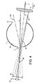
- the effect of this chromatic aberration is that the projected size of the receiver beam at the SEP location is a predictable function of the wavelength.
- the size of SEP 13 is chosen to match the projected beam size at a given (i.e., predetermined) wavelength for an ideal flat/smooth nominal specimen (specimen not shown).
- parameters involved in effecting the SEP size are the lens material (e.g., glass, plastic, etc.), the apertures in the receiver optics, the conjugate positions, and the focal length of the lens(es) (the desired size of the sample area to be measured influences these parameters).
- the short wavelengths have a larger projected beam size at the SEP than do the long wavelengths (note that an alternative implementation may have a larger projected beam size for the long wavelengths compared to the short wavelengths), as schematically represented by long wavelength specular image 32 and short wavelength specular image 34 , which correspond to specular rays projected onto SEP 13 by an ideally flat/smooth specimen for wavelengths respectively longer and shorter than the given (i.e., predetermined) wavelength.
- long wavelength focus 36 and short wavelength focus 38 are also identified in FIG. 4 for clarity.
- the longer wavelengths would have a projected beam size smaller than the SEP.
- Any specimen with surface variations will cause longer wavelengths to begin to "see” (i.e., receive specular components from) the edge of the SEP (i.e., longer wavelength radiation originating from the integrating sphere interior surface outside SEP 13 will be reflected by the sample surface into the viewing beam received by receiver 20 ). That is, for a given wavelength, contributions of a specular component to the measured signal will be a function of the specimen surface characteristics because the projected size of the viewing beam for a given wavelength is, in part, a function of the sample surface characteristics.
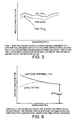
- the proportional size variation is wavelength encoded in a single SCE measurement by virtue of the chromatic aberration of the receiver beam. If the specimen is measured SCI also, then much can be determined about the specimen from these two measurements, including: color, gloss/matte, "orange peel", gross flatness, etc.
- an SCI measurement may bo taken separately by using a sphere with a movable portion that selectively plugs an SEP port, an instrument equipped with two or more receivers, such as that disclosed in commonly assigned U.S. Patent Application Serial No. 09/097,312 (described hereinbelow following further description of the present invention), allows for measuring SCE and SCI simultaneously, which further simplifies the process.
- an SEP size may be chosen relative to the beam size such that the nominal crossover wavelength is roughly between 400 nm and 500 nm for an ideal polished sample surface.
- the analysis may include corrections for sample translucency and/or uniformity. Additionally, where additional receivers (e.g., having larger area beams) are used, the analysis may also include corrections for receiver beam uniformity and for better determining the sample's Fresnel reflection values, etc.
- a configuration may include an additional SCE port which has an SEP size relative to the receiver beam size (and preferably also has the receiver's chromatic aberration eliminated) such that surface effects cause essentially no deviations in measured SCE reflectance over the wavelengths of interest, and the measured SCE reflectance signal for this port may be used instead of, or in addition to, the SCI reflectance measurement to determine deviations from ideal for the SCE port which is subject to variations in measured spectral reflectance due to chromatic aberration.
- the receiver viewing beam and/or SEP may be implemented to better distinguish certain surface characteristics and/or to isolate effects in certain directions.
- the circular SEP configuration with a circular receiver beam as described herein is not necessarily the most advantageous configuration for sensitivity of surface character measurement because the central area of the beam cross-section provides little surface modulated signal, and thus the modulation depth is not optimized.
- Such a beam geometry is typical for colorimetry and is thus more easily accepted by the industry.
- the center of the receiver's viewing beam may be "cored out" to form a hollow cylinder having an annular cross-section and the SEP may be formed as an annular opening (or trap), and thus the surface character effect on the modulation of the signal will have greater depth, or contrast.
- This latter configuration of a receiver and associated SEP is particularly well suited for implementation as a coaxial receiver, in accordance with the description of coaxial receivers in commonly assigned U.S. Patent Application Serial No. 09/097,312 (as described hereinbelow following further description of the present invention).
- the annular/cored-out receiver may surround a coaxially disposed SCI receiver which receives specular components from the circular region interior the annular SEP port or trap.
- the SEP may be formed as an elongated rectangle with an appropriately matched receiver beam shape.
- Such an arrangement may be configured for sensitivity to the spatial frequency content of the sample surface along one direction only (e.g., by selecting the beam size relative to the SEP size in each direction such that only one direction is responsive to wavelength-encoded projected beam size variations due to surface effects), which allows discriminating surface texture variations as a function of the rotational orientation of the sample.
- a series of such rectangular “slats” may be used with a "striped" beam cross section to increase the amount of light flux available and to provide a beam cross section with a more equal aspect ratio. The spacing of such slats may be chosen to optimize the measurement sensitivity to a particular range of spatial frequencies.
- Such configurations using a rectangular SEP and a rectangular beam shape are advantageously implemented using multiple receivers.
- the orientation and/or the spacing of the slats can be different for each receiver to allow characterization of multiple surface components with one measurement actuation.
- two such configured receivers may have the same orientation of the rectangle length relative to a normal to the sample but may be azimuthally displaced by about 90° in order to concurrently measure spatial frequency content in orthogonal directions of the sample.
- the spatial frequency content in orthogonal directions of the sample may be concurrently measured by two such configured receivers which have orthogonally orientated relationships of the rectangle length relative to a normal to the sample and have a common viewing plane (i.e., azimuthally displaced by about 0° or 180°).
- the receivers may be disposed coaxially or may be disposed at slightly different viewing angles.
- the hereinabove embodiment is implemented in a spectrophotometer to advantageously discriminate color and surface characteristics in a single measurement
- the method of the present invention may be implemented by myriad optical arrangements, not limited to concurrently measuring these appearance attributes.
- the hereinabove describcd embodiment has been described for a conventional spectrophotometer with an integrating sphere having a diffuse reflectivity measurement configuration (i.e., in which the specimen is illuminated diffusely by virtue of the sphere, and one or more receiver lenses are used to collect the light reflecting from a defined area of the specimen), the "reverse" geometry method could also be used to implement the present invention.
- the specimen may be illuminated by a defined beam of projected light, with the integrating sphere used to collect the reflected light and to direct the light to an analyzing detector.
- the present invention may also be implemented with an SCI mode receiver having chromatic aberration.
- the SCI receiver may have a circular beam cross-section, and an annular SEP port having an interior highly and diffusely reflective center area (i.e., within the inner boundary of the annulus) would be located opposite the SCI receiver such that the periphery of the projected specular beam for the SCI receiver would overlap the inner boundary of the annulus for wavelengths shorter (or longer, depending on the design) than a given (i.e., predetermined) wavelength for an ideal flat/smooth nominal specimen.
- the port shape and/or receiver beam shape may be appropriately designed to isolate or enhance sensitivity to spatial frequency content along a given direction.
- the port may vary in size in one direction only, or the beam shape and/or port shape may be elongated such that isotropic changes in port dimension nevertheless affects predominantly one direction of the received beam.
- multiple variable ports may be implemented, and may be oriented to be sensitive to spatial frequency content along different directions of the sample.
- the present invention provides a method for measuring surface effects of a sample such that the method is well suited for implementation with a spectrophotometer used in colorimetry. Additionally, the method permits measurement of and distinction between color and surface appearance with a single measurement using a single instrument (e.g., spectrophotometer). Moreover, such characterization of color and surface effects requires acquiring a relatively small amount of data, and performing a relatively small amount of calculations, thus providing for rapid measurement and characterization. In addition, the present invention may be implemented with a small size (compact) and low weight (e.g., portable) instrument, without requiring moving parts, thus resulting in reduced instrument cost.
- various implementations of the present invention may advantageously employ two or more receivers, which may be implemented in accordance with the invention disclosed by the present applicant in U.S. Application Serial No. 09/097,312. That invention provides an integrating sphere which features the capability of multiple measurement modes (e.g., multiple SCE, SCE and SCI, multiple SCI), multiple areas-of-view for a given measurement mode, multiple viewing angles per measurement mode, and combinations thereof, as will be more fully appreciated hereinbelow.
- multiple measurement modes e.g., multiple SCE, SCE and SCI, multiple SCI
- integrating sphere is not intended to limit the interior cavity to a spherical shape, but is used, as understood by one of ordinary skill in the art, to refer to a class of instruments used for measuring light reflectance of a test sample; different shapes of the interior cavity may be implemented.
- a port generally refers to a region of the integrating sphere in which the highly reflective, optically diffuse inner surface is absent, and typically includes an aperture formed through the inner wall.
- a colorimeter integrating sphere includes a sample port and one or more viewing ports, and, as described hereinbelow, may also include a specular exclusion port (SEP) and/or a reference port.
- SEP specular exclusion port
- a viewing port has an associated receiver and is characterized by a viewing beam representing the ray bundle of optical radiation received by the associated receiver directly from optical radiation reflected by the sample.
- the areal cross section of the viewing beam of a receiver at the associated viewing port may be less than or equal to the overall cross-sectional area of the viewing port itself. Where the port area is greater than the receiver area, the region of the port surrounding the receiver portion typically has low reflectivity.
- a ray viewing angle refers to the angle between a ray of the viewing beam and the normal to the sample surface where the ray intersects the sample surface.
- a viewing beam plane refers to a plane defined by a ray in the viewing beam and the normal to the sample surface at the intersection of the sample surface and the ray.
- An azimuthal angle between two viewing beams is represented by the angle, in a plane perpendicular to a sample normal, between two viewing planes of the respective viewing beams.
- a viewing beam may include rays which deviate from each other (i.e., are not parallel) within some range (e.g., Commission Internationale De L'Eclairage (CIE) Publication Number 15.2 (Colorimetry), 1986, prescribes that the angle between the viewing beam axis and any ray of the viewing beam should not exceed 5°), thus resulting in a finite range of azimuthal angles of the viewing rays relative to a given plane, as well as a finite range of viewing angles for the viewing beam.
- CIE Commission Internationale De L'Eclairage
- a viewing beam is typically symmetric about a viewing axis (i.e., the central axial ray of the viewing beam), this viewing axis is typically used for describing the (effective) viewing angle for the viewing beam as well as the (effective) azimuthal angle relative to the viewing beam.
- a second port is sometimes said to be opposite relative to a first port (also referred to the first port having an opposing port) if a mirror image beam of the first port's viewing beam mirrored from the sample surface (i.e., each ray of the ray bundle specularly reflected by the sample surface) is substantially overlapped by (e.g., encompassed by) the second port such that the specular component of the first port is completely or effectively excluded.
- the second port encompasses substantially the entire region from which optical radiation specularly reflected from the sample surface into the viewing beam of the first port would originate if the second port were not there (i.e., if the region were diffusely scattering).
- the second port is located at the portion of the integrating sphere wall corresponding to substantially all specular (regular) components for the first port.
- two ports are said to be opposite each other if the first port is opposite the second port (as described) and the second port is also opposite the first port such that the mirror image beam of the second port's viewing beam mirrored from the sample surface is substantially overlapped by the first port.
- a port's receiver area may be smaller than the port's area, if two ports are opposite each other, it does not necessarily follow that the viewing beams view overlapping sample surface regions or that the viewing beams have equal viewing angles: the mirror image of each viewing beam may project into the extra-receiver region of the opposing port, and the extra-receiver region of the port(s) may be of sufficient area to allow for differences in viewing angles and/or viewed sample surface regions.
- adjacent, non-concentric (e.g., non-overlapping) sample surface regions may be viewed by ports which are opposite to each other and have the same viewing angle; or, a common, overlapping surface region may be viewed by ports which are opposite to each other and have slightly different viewing angles.
- a second port may be opposite relative to a first port but the first port may not be opposite to the second port: the viewing beam of the second port mirrored from the sample surface may not be substantially overlapped by the first port, whereas the viewing beam of the first port mirrored from the sample surface may be substantially overlapped by the second port.
- the first port and the second port i.e., their viewing planes
- the first port and the second port may be azimuthally displaced by about 180° but with unequal viewing angles such that the second port encompasses a region of the integrating sphere inner surface from where the regular component for the first port receiver would originate but the viewing angle of the second port is such that the first port is not located at the region from where the specular component for the first port arrives.
- the first and second ports may be azimuthally displaced by about 180° with equal viewing angles, but viewing non-concentric (e.g., non-overlapping) sample surface regions, such that the second port encompasses a region of the integrating sphere inner surface from where the regular component for the first port receiver would originate but the viewed sample region displacement is such that the first port is not located at the region from where the specular component for the first port arrives.
- two ports may have any respective combination of viewing angles (including equal viewing angles), and may be azimuthally displaced by any angle not equal to about 180° with the first port's projected beam substantially overlapped by the second port, the ports thus viewing non-concentric (e.g., non-overlapping) surface regions of the sample.
- a second port is said to be non-opposite to a first port if the first port's viewing beam mirrored from the sample surface (i.e., the projection of the first port's viewing beam) is not substantially overlapped by the second port, the first port viewing beam having a not insubstantial specular component.
- the ports i.e., their viewing planes
- the ports may be displaced by an azimuthal angle different from 180° and have any combination of viewing angles provided neither port's viewing beam projection is substantially overlapped by the other port.
- two non-oppositely disposed ports may nevertheless be azimuthally displaced by about 180° if, for example, they have sufficiently different viewing angles and/or they view sufficiently non-concentric (e.g., non-overlapping) sample regions, such that the projection of each beam is not substantially overlapped by the other port.
- spatial relationships between ports is a general one which depends on the relative orientations of the viewing beams with respect to the sample plane (e.g., their respective viewing angles and viewing regions, and their relative azimuthal displacement), and which does not depend on a specific integrating sphere geometry or on a predetermined relationship of the viewing beams to each other or to the integrating sphere geometry.
- each viewing port has a viewing beam that is directed towards the sample along a viewing axis about which the viewing beam is symmetric and which intersects the sample plane at a common point which is typically also the point of intersection of the sample plane by a normal thereto which is a central axis of the integrating sphere (assuming the integrating sphere has a spherical cavity, this central axis passes through the center of the spherical cavity and the center of the sample port).
- a viewing beam that is directed towards the sample along a viewing axis about which the viewing beam is symmetric and which intersects the sample plane at a common point which is typically also the point of intersection of the sample plane by a normal thereto which is a central axis of the integrating sphere (assuming the integrating sphere has a spherical cavity, this central axis passes through the center of the spherical cavity and the center of the sample port).
- the multi-channel integrating sphere invention is not limited to ports having such spatial symmetry with respect to a common axis which is symmetric relative to the integrating sphere cavity. It is also understood that the foregoing terminology is simply a chosen convention for clarity of exposition, and that there are other ways of describing the spatial relationships between or among ports and their viewing beams.
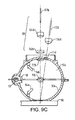
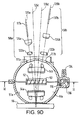
- FIGS. 9A-9E there is shown an integrating sphere 51 according to an embodiment of the multi-channel integrating sphere invention. More specifically: FIG. 9A depicts an isometric view, with certain features of the receivers exposed for clarity, of an integrating sphere according to an embodiment of the multi-channel integrating sphere invention; FIG. 9B depicts a plan (top) view, from the receiver side, of the integrating sphere, also with certain features of the receivers exposed for clarity; FIG. 9C is a cross-sectional view of the integrating sphere along line IC-IC of FIG. 9B; FIG. 9D is a cross-sectional view of the integrating sphere along line ID-ID of FIG. 9B ; and FIG. 9E is a cross-sectional view of the integrating sphere along line IE-IE of FIG. 9D .
- Integrating sphere 51 includes two halves to facilitate construction: the two halves may be machined properly to fit one within the other, and appropriately secured with standard fastening mechanisms.
- Integrating sphere 51 includes a cavity having a highly reflective, optically diffuse surface 51a illuminated with a light source 52 (lamp) which may be coupled to the integrating sphere 51 in a conventional way using an entrance port 53 (aperture in the integrating sphere). Power to the lamp is supplied via lamp leads 132a , 132b , and 132c .
- the light source 52 may be a pulsed lamp of high intensity, short duration, and with a full "white" spectrum, such as a pulsed Xenon lamp. The effect is to diffusely illuminate sample 56 at port 57 , in a conventional way.
- lamp 52 is external to the integrating sphere 51 cavity, housed in a lamp cavity 130 adjoined to integrating sphere 51 .
- Lamp 52 may alternatively be placed at least partially internal the cavity of integrating sphere 51 , and may be placed substantially internal to the integrating sphere cavity to achieve the following advantages: optical flux efficiency, mechanical simplicity, small size, and reduction of port apertures which allows a smaller integrating sphere 51 to be used for a given sample port 57 size while conforming to standards for integrating sphere design.
- the lamp may be external to the sphere and projection optics (e.g., lens, etc.) may be used to relay or project flux from the lamp through the entrance port and to a spot at the far side of the integrating sphere interior.
- baffle 54a with highly reflective, optically diffuse surface is used in a convcntional way to block light rays from directly illuminating the sample 56 (shown in FIGS. 9C and 9D , only) from the lamp, or from the entrance port 53 if used.
- baffle 54b prevents light rays originating at entrance port 53 or lamp 52 from directly illuminating portions of the sphere surface from where specular flux for the SCI receivers originates.
- diffusely illuminated sample 56 is viewed by multiple optical receivers 58a-d (i.e., four receivers in the present embodiment), each of which receives a portion of optical radiation reflected from sample 56 and provides it to a sensor or detector used to analyze the spectral content of the received optical radiation. More particularly, shown are multiple viewing ports including spocular-component-excluded (SCE) port 111a, SCE port 111b, specular-component-included (SCI) port 111c, and SCI port 111d.
- SCE spocular-component-excluded
- SCI specular-component-included
- Each port has an associated receiver comprising associated receiver optics (shown exposed) according to the present embodiment: SCE port 111a has a receiver 58a including aperture stop 122a, lens 124a, and fiber 117a; SCE port 111b has receiver 58b including aperture stop 122b, lens 124b, and fiber 117b; SCI port 111c has receiver 58c including aperture stop 122c , lens 124c, and fiber 117c; SCI port 111d has a receiver 58d including aperture stop 122d, lens 124d, and fiber 117d .
- Each receiver 58a-d is directed at sample port 57 along a corresponding one of viewing axes 126a, 126b, 126c, and 126d, which according to the present embodiment, converge to a common point of intersection at the surface of sample 56. It is understood that actual components of the receivers may differ, depending on design criteria, applications, preference, etc.
- the optical receivers 58a-d of the present embodiment are located at a same predetermined viewing angle from the sample normal (less than 10° to comply with standards for colorimetry, 8° in the present embodiment) and each has its own associated receiver viewing port 111a-d in the integrating sphere 51 .
- the receivers For each viewing mode (i.e., SCE and SCI), the receivers have two subtense angles, corresponding to two sample area sizes.
- the optical receivers 58a-d and their respective receiver viewing ports 111a-d are displaced azimuthally, thereby advantageously maintaining the same predetermined viewing angle from the sample normal, and the azimuthal displacements are chosen to conveniently fit optical receivers 58a-d (and their associated viewing ports 111a-d ), each designed with a combination of chosen parameters.
- the parameters include, but are not limited to, the measured size of the sample surface, the subtense angles of the receivers, and the inclusion (SCI) or exclusion (SCE) of the specular-reflected light. Additional and non-exclusive parameters (not used in the present embodiment) include multiple viewing angles, and different viewing regions of the sample surface (e.g., non-overlapping, non-concentric).
- Integrating sphere 51 includes one SCE mode receiver and one SCI mode receiver for each of two different measured areas-of-view (four receivers total).
- the two SCE receivers 58a and 58b having viewing axes 126a and 126b which intersect the sample at a common point, have equal viewing angles and are azimuthally displaced by 180°, and are thereby opposite each other.
- SCE ports 111a and 111b are sized appropriately to exclude substantially all specular rays for the respectively opposing associated SCE receivers 58b and 58a .
- SCI receivers 58c and 58d are placed out of the plane defined by the viewing beams of SCE receivers 58a and 58b , and also at the same predetermined viewing angle from the common sample normal located at the intersection of the sample by the viewing axes, such that the specular component is provided by the inclusion of the integrating sphere surface (no ports) at the regions intersected by the respectively projected SCI receiver viewing beams.
- each SCE port is designed to exclude substantially all specular components for the opposing SCE receiver.
- Such a shared arrangement of SCE/viewing ports advantageously reduces the total port area required to implement a plurality of SCE ports.
- alternative embodiments of the multi-channel integrating sphere invention may include a separate aperture (port) which does not have an associated receiver and which is appropriately sized and located opposite to an SCE receiver to exclude the specular component origin of the reflected light.
- Such an aperture is common practice which is known as a specular exclusion port (SEP, also referred to as a light trap), and generally refers to a portion of the integrating sphere's inner surface which does not reflect light, but substantially absorbs it, and which is opposite to an SCE port receiver.
- SEP specular exclusion port
- integrating sphere 51 preferably includes an added receiver, having associated reference port 116, which provides a measurement of the illumination which is not a direct reflection from sample 56 and preferably not directly incident from lamp 52 or lamp port 53 .
- the viewing beam received via reference port 116 is referred to as a reference beam, and can be used to correct or to control the lamp 52 fluctuations and to compensate for the influence of the sample 56 reflectance on the integrating sphere 51 illumination.
- reference port 116 location and its associated receiver characteristics are such that only light diffusely reflected from optically diffuse surface 51a of integrating sphere 51 is received.
- the reference beam is conveniently redirected by fold mirror 136 into an optical fiber (not shown) coupled to reference fiber mount 134. It is appreciated that for the multi-channel integrating sphere invention, this reference path is not considered or counted as one of the multiple measurement paths.
- the spectral content of the optical radiation collected (received) by each of the multiple receivers is analyzed by any of a variety of conventional means, such as filters or spectroscopic optics and appropriate signal processing (not illustrated).
- the optical radiation collected (received) concurrently (in parallel) by the multiple optical receivers 58a-d is detected (i.e., converted from an optical to an electrical signal) in parallel for each receiver, and further, is also detected in parallel spectrum-wise (i.e., for each receiver, the complete spectrum is detected in parallel).
- the optical radiation received by the multiple optical receivers 58a-d is detected substantially simultaneously.
- Analysis of the detected signals may be performed, for example, in order to condition the detected signal and calculate the sample's color using standard formulae, as described in the referenced CIE publication, supra.
- receiving optical radiation is distinguished from detecting optical radiation; the former is used to refer to optical radiation scattered/reflected from the sample surface being coupled into (accepted by) a receiver, whereas the latter is used to refer to received optical radiation being sensed (e.g., converted to an electrical signal) by a detector.
- receivers are said to concurrently receive optical radiation when optical radiation scattered/reflected from the sample impinges on the receivers in parallel; this concurrent reception does not mean that the concurrently received optical radiation is necessarily also detected concurrently or in parallel, although, as described hereinabove and more fully hereinbelow, such concurrent or parallel detection is generally preferable.
- such parallel detection is implemented by a single spectrometer with a two dimensional detector array and a segmented entrance slit and a single diffraction grating, as described by Palumbo et al. in the commonly assigned U.S. application Serial No. 09/041,233, entitled “Concentric Spectrometer", filed March 12,1998, and in the Analytica Chimica Acta article, supra.
- Each segment of the slit is illuminated by a corresponding receiver path, which may be accomplished with fiber optic light guides 117a-117d .
- the multiple optical receivers 58a-38d can be conveniently and advantageously detected simultaneously using a single common spectrometer.
- the reference beam may also be advantageously detected and processed in parallel by such a multi-channel spectrometer.
- alternative apparatuses and/or methods may be implemented for concurrently, but not necessarily precisely simultaneously, detecting the optical signals received in parallel by the different SCI/SCE receivers. For instance, signal detection may be time multiplexed among the channels.
- the channels need not be synchronously sampled; e.g., each channel may be independently gated and/or have a different sampling rate and/or sampling time.
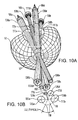
- FIG. 10A there is illustrated a cut-away view of schematic integrating sphere 51 with schematic depictions of ray bundles 138a-138d for corresponding receivers 58a-58d and associated ports 111a-111d , so that the relationship among the viewing beams of a preferred embodiment may be visualized. Also, referring to FIG. 10B, placed in relation to FIG.
- FIGS. 10A and 10B there is shown a projection onto a plane parallel to the sample surface of receiver view ports 111a-111d , viewing axes 126c and 126d (and their projections) of SCI ports 111c and 111d , and viewing axes 126a and 126b of SCE ports 111a and 111b , so that the mutual relationships of the ports and viewing axes at the rear (i.e., top portion away from sample port 7) of the integrating sphere may be more easily visualized.
- FIGS. 10A and 10B the schematic depiction of ray bundles preserves the general spatial orientation, but does not preserve the relative sizes, of viewing beams and ports shown in FIGS. 9A-9E . Also identified for reference in FIG.
- FIG. 10B are: an example of an azimuthal displacement angle 112 between SCI ports 111c and 111d (i.e., angle between the viewing planes); common sample normal 110 located at the intersection of the sample by the viewing axes 126a-d ; circle 59 defined by the projection of the points of intersection of the viewing axes at the same viewing angle and their corresponding viewing ports; and central points 118 of origination of specular inclusion viewing beams at the rear (i.e., internal surface away from the sample port) of the integrating sphere 51 , as would be reflected from the specular reflecting surface of the sample 56.
- FIG. 10A and 10B together show the relationship between the ports and the specular components of the beams after reflecting off the sample.
- FIGS. 9A-9E illustrate an embodiment of an integrating sphere having multiple viewing ports, with all of the viewing ports have equal viewing angles, the two SCI ports having different sample areas of view, and the two SCE ports also have two different sample areas of view.
- the SCE ports are disposed opposite each other such that each excludes the specular components for the receiver of the other, thus reducing the overall port area of the integrating sphere.
- the maximum number and size of ports is limited by the sphere diameter which, in order to comply with existing standards, cannot have a total port area (sum of all apertures) that exceeds a certain percentage (3 to 5%, depending on the standards of choice) of the total internal surface area of the sphere.
- the sample port must be slightly larger than the overall region viewed by the receivers to allow for sample translucency (according to existing standards) and to allow for alignment tolerances.
- the azimuth angles typically are chosen to adequately separate the viewing ports from one another and from portions of the sphere comprising the origins of specular light for the SCI receivers.
- These origins of specular light are areas of the sphere surface that are opposite their respective SCI receiver apertures as mirrored from the sample surface, and are of a size that includes preferably all rays that the receiver optics collect by such specular reflection from the sample surface. No ports should intrude those portions of the sphere surface so described.
- Light traps (SEP ports) or other SCE ports used to remove the specular origin for SCE receivers must be of sufficient size to exclude preferably all rays that the receiver optics would collect by specular reflection from the sample surface.
- the size of the receiver ports, specular exclusion ports and specular inclusion origins required are dependent on several parameters of each respective receiver design, including: the sample area-of-view size, the receiver subtense angle, the aperture and focal conjugate positions of a beam forming optic if used (such as a lens), aberration characteristics of the beam forming optic, margin for each beam to ports (respective receiver aperture and specular exclusion) as prescribed by existing standards and/or alignment tolerances, size of the integrating sphere, etc.
- the receivers' axes are at a same predetermined angle from the sample normal axis, and converge to a common point on the sample surface, the point forming the center of the sample port aperture.
- SCE ports 111a and 111b are shown opposite each other, as described, alternatively they may be positioned non-opposite each other (i.e., such that neither port is opposite the receiver of the other port), with each SCE port's receiver having an opposing SEP to exclude the specular component (e.g., (i) SCE ports azimuthally displaced by about 180° but with unequal viewing angles, or (ii) SCE ports azimuthally displaced by an angle not equal to about 180° and having any respective combination of viewing angles, including equal viewing angles).
- specular component e.g., (i) SCE ports azimuthally displaced by about 180° but with unequal viewing angles, or (ii) SCE ports azimuthally displaced by an angle not equal to about 180° and having any respective combination of viewing angles, including equal viewing angles).
- the illustrative integrating sphere of FIGS. 9A-9E may include two additional SCE ports which are opposite to each other (or a single additional SCE port with opposing trap).
- the additional opposing SCE ports may be: (i) azimuthally displaced by about 0° (or, equivalently, by 180°) but at different viewing angles, each one of the additional SCE ports having any general viewing angle and/or area-of view, or (ii) displaced azimuthally by an angle not equal to about 0° (or equivalently, 180°) and having any viewing angles, including viewing angles equal to each other and to those of SCE ports 111a and 111b .
- SCI ports 111c and 111d alternatively may be displaced by different azimuthal angles (e.g., 90°) and/or disposed at different viewing angles from each other and/or modified to have the same viewing area. Further, one or more additional SCI ports may be added at any appropriate locations on the integrating sphere.
- azimuthal displacement e.g. of about 90°
- various appearance or surface characteristics e.g., striations, texture, etc.
- the sample e.g., fabric, weaves, embossings, etc.
- viewing axes may intersect the sample at different locations and the corresponding viewing beams may view overlapping sample regions (e.g., a larger viewing area of a first viewing beam encompassing a smaller viewing area of a second viewing beam, or may view two viewing areas each viewing both a common and a separate viewing region) or non-overlapping sample regions.
- Each sample region may be viewed by more than one viewing beam.
- the integrating sphere may include coaxial receiver paths (i.e., a single port with a plurality of receivers). More particularly, coaxial receivers can be provided to increase the number of available receivers.
- An implementation may employ coaxial lenses of different focal lengths and correspondingly different diameters, as would be desired to provide different areas-of-view, and placing them one in front of the other, smaller diameters closer to the sample. The larger lens(es) would peer around the smaller, the latter forming a central obscuration to the larger. The central obscuration can often be tolerated simply as a loss in available sample light for the larger lens(es).
- the focus of the smaller lens(es) can be transmitted to the analysis means by providing a fold mirror or a fiber optic guide or similar, so as to minimize interference with the larger receiver(s).
- curved mirrors may be used instead of the lenses.
- Another implementation for providing coaxial receivers employs zone plates: a zone plate with a Fresnel pattern is known to have multiple focal lengths, for which a receiver can be used at or near two or more foci, using the transmitting/folding techniques already described.
- Yet another implementation for providing coaxial receivers is by combining their axes using beamsplitter(s) as beam combiners.
- the coaxial receivers may be implemented as all SCI receivers, all SCE receivers, or a combination of SCI and SCE receivers.
- the specular component for SCE receiver(s) implemented coaxially with SCI and/or SCE receiver(s) may be blocked by another SCE port (coaxial or individual) or by a SEP.
- SCE port coaxial or individual
- SEP SCE port
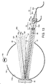
- FIG. 13 schematically shows an implementation of a coaxial receiver according to an illustrative embodiment of the multi-channel integrating sphere invention.
- coaxial small area receiver 80 and large area receiver 82 sharing viewing port 81 are both SCE receivers, and are shown as opposed by an SEP 86 which is schematically shown as an absence of a portion of integrating sphere 100 and its inner diffuse, highly reflective surface 100a .
- Small area SCE receiver 80 and large area SCE receiver 82 have a common receiver axis 88 along which the receivers are directed toward sample 90 which is diffusely illuminated by optical radiation indirectly incident from lamp 102 via integrating sphere 100 .
- Small area receiver 80 includes lens 80a optically coupled to optical fiber 80b
- large area receiver 82 includes lens 82a optically coupled to optical fiber 82b
- Lens 82a includes a central obscuration area 82c to prevent receiving optical radiation from the small area receiver, thus ensuring that large area receiver 82 only receives optical radiation directly from sample 90 .
- an integrating sphere in accordance with the multi-channel integrating sphere invention may include one or more ports each having coaxial receiver arrangements, and that additional ports having single receivers may also be included in combination with one or more ports having coaxial receivers.
- an integrating sphere according to the multi-channel integrating sphere invention includes myriad features, advantages, and attendant advantages.
- advantages of receiving a plurality of viewing beams in parallel include: multiple data sets may be provided by a single measurement step, no moving parts or time delay required to change modes (e.g., SCE, SCI, different areas of view for SCE and/or SCI), electrical power is efficiently used (e.g., reduced time needed to power lamp compared to multiple measurements, no parts need be electromechanically moved), component sizes may be small, and overall structure will be durable (e.g., from no moving parts).
- SCI and SCE modes for a given area-of-view can quickly and conveniently provide an estimate of the gloss of the sample surface.
- the presence of multiple areas-of-view provides capability for quickly measuring or estimating sample uniformity and/or sample translucency.
- various azimuthal angles between SCE and/or SCI provide the ability to extract other appearance parameters (in addition to the color) from the data sets acquired, such as surface flatness or texture. Having a simultaneous reference measurement also provides optimum correction.
Landscapes
- Physics & Mathematics (AREA)
- General Physics & Mathematics (AREA)
- Health & Medical Sciences (AREA)
- Life Sciences & Earth Sciences (AREA)
- Chemical & Material Sciences (AREA)
- Analytical Chemistry (AREA)
- Biochemistry (AREA)
- General Health & Medical Sciences (AREA)
- Immunology (AREA)
- Pathology (AREA)
- Investigating Or Analysing Materials By Optical Means (AREA)
- Spectrometry And Color Measurement (AREA)
Claims (19)
- Verfahren zum Beschreiben von Oberflächeneffekten einer Probe bzw. eines Musters (6), wobei das Verfahren die Schritte aufweist:(a) an einem Empfänger (20) wird optische Strahlung (26, 26a, 26b) empfangen, die von der Probe bzw. dem Muster (6) reflektiert oder gestreut worden ist, wobei die optische Strahlung (26, 26a, 26b) gespiegelte Komponenten beinhaltet, die durch Wellenlängen entsprechend der chromatischen Aberration des Empfängers (20) räumlich codiert sind;(b) ein Signal, welches die optische Strahlung (26, 26a, 26b) darstellt, wird verarbeitet, um ein Maß bzw. eine Größenordnung von Oberflächeneigenschaften bzw. Oberflächencharakteristiken basierend auf den gespiegelten Komponenten bereitzustellen, die durch Wellenlängen entsprechend der chromatischen Aberration räumlich codiert sind;
gekennzeichnet durch:(c) die Probe bzw. das Muster (6) wird an einem Probenport bzw. einer Musteröffnung (7) von einer integrierenden Sphäre (1) bzw. Kugel angeordnet, und zwar derart, dass die Probe bzw. das Muster (6) nur durch eine Lichtquelle (2) beleuchtet wird; und(d) der Empfänger (20), der ein Empfänger ist, der eine spiegelnde Komponente ausschließt, wird über einen Port bzw. eine Öffnung (5) der integrierenden Sphäre (1) bzw. Kugel angewandt bzw. angeordnet. - Verfahren zum Beschreiben von Oberflächeneffekten einer Probe bzw. eines Musters nach Anspruch 1, wobei das Verfahren die Schritte aufweist:die Größe eines Ports bzw. einer Öffnung oder einer Klappe bzw. einer Falle, die im Wesentlichen gegenüber dem ersten Empfänger angeordnet ist, derart, dass eine gespiegelte Projektion der optischen Strahlung, die durch den ersten Empfänger empfangen wird, den Bereich überlappt bzw. überdeckt, der durch den Port bzw. die Öffnung oder die Klappe bzw. die Falle, beinhaltet ist, wird zu jeder von einer Vielzahl von Größen eingestellt;an dem ersten Empfänger wird für jede von der Vielzahl von Größen des Ports bzw. der Öffnung oder der Klappe bzw. der Falle, ein korrespondierendes optisches Strahlungssignal empfangen, das von der Probe bzw. dem Muster (6) reflektiert oder gestreut worden ist; unddie korrespondierenden optischen Strahlungssignale werden verarbeitet, um ein Maß bzw. Ausmaß oder eine Größenordnung von Oberflächeneigenschaften bzw. Oberflächencharakteristiken bereitzustellen.
- Verfahren nach Anspruch 1 oder Anspruch 2, das den Schritt des Empfangs eines zweiten optischen Signals von der Probe bzw. dem Muster (6) aufweist, wobei das zweite optische Signal spiegelnde Komponenten bzw. Spiegelkomponenten beinhaltet, die von der Probe bzw. dem Muster (6) reflektiert worden sind.
- Verfahren nach Anspruch 3, wobei das optische Signal und das zweite optische Signal gleichzeitig empfangen werden.
- Verfahren nach irgendeinem der Ansprüche 1 bis 4, wobei der Verarbeitungsschritt das Verarbeiten der Signale beinhaltet, die die optische Strahlung darstellen, um eine Farbmessung für die Probe bzw. das Muster (6) bereitzustellen, wobei dadurch sowohl eine Farb- als auch Oberflächeneffektkennzeichnung bzw. Oberflächeneffektcharakterisierung für die Probe bzw. das Muster (6) von einer gemeinsamen Messung bereitgestellt wird.
- Verfahren nach irgendeinem der Ansprüche 1 bis 5, wobei das Maß bzw. Ausmaß oder die Größenordnung von Oberflächeneigenschaften bzw. Oberflächencharakteristiken ein Oberflächeneffektindex ist, der stellvertretend für eine Oberflächenrauhigkeit ist, und durch Berechnung einer Funktion, die den räumlichen Frequenzinhalt der Oberfläche repräsentiert bzw. darstellt, unabhängig bestimmt wird.
- Verfahren nach Anspruch 6, wobei der Oberflächeneffektindex auf einer Abweichung zwischen spiegelnder Reflexion bzw. Spiegelreflexion für die gemessene Probe bzw. das gemessene Muster (6) relativ zu einer ideal ebenen und glatten Probe bzw. eines ideal ebenen und glatten Musters (6) basiert.
- Verfahren nach Anspruch 6, wobei der Oberflächeneffektindex auf einer Verschiebung der Übergangsfrequenz eines Spiegel- bzw. Reflexionsfehlers basiert.
- Verfahren nach Anspruch 1 oder Anspruch 2, wobei das Maß bzw. Ausmaß oder die Größenordnung der Oberflächeneigenschaften bzw. Oberflächencharakteristiken eine Funktion ist, die den räumlichen Frequenzinhalt der Oberfläche darstellt.
- Verfahren nach Anspruch 9, wobei das Maß bzw. Ausmaß oder die Größenordnung von Oberflächeneigenschaften bzw. Oberflächencharakteristiken ein Maß bzw. eine Größenordnung der Erscheinung bzw. des Sichtbarwerdens ist, die entsprechend der Funktion berechnet wird, die den räumlichen Frequenzinhalt der Oberfläche darstellt.
- Verfahren nach Anspruch 10, wobei das Maß bzw. Ausmaß oder die Größenordnung der Erscheinung bzw. des Sichtbarwerdens eine Anzeige von Glanz/Matt, ,,orange peel bzw. Orangenschaleneffekt", oder Gesamtflachheit bzw. Gesamtebenheit ist.
- Vorrichtung zum Beschreiben von Oberflächeneffekten einer Probe bzw. eines Musters (6), die aufweist:dadurch gekennzeichnet, dassMittel (20) um optische Strahlung (26, 26a, 26b) zu empfangen, die von der Probe bzw. dem Muster (6) reflektiert oder gestreut wird, wobei die optische Strahlung (26, 26a, 26b) gespiegelte Komponenten bzw. Spiegelkomponenten beinhaltet, die durch Wellenlängen entsprechend der chromatischen Aberration räumlich codiert sind;Mittel um ein Signal zu verarbeiten, das die optische Strahlung (26, 26a, 26b) darstellt, um ein Maß bzw. Ausmaß oder eine Größenordnung von Oberflächeneigenschaften bzw. Oberflächencharakteristiken bereitzustellen, die auf den gespiegelten Komponenten basieren, die durch Wellenlängen entsprechend der chromatischen Aberration räumlich codiert sind;eine integrierende Sphäre (1) bzw. Kugel; undeine Lichtquelle (2);
die Probe bzw. das Muster (6) an einem Probenport bzw. einer Musteröffnung (7) der integrierenden Sphäre (1) bzw. Kugel angeordnet ist, und zwar derart, dass die Probe bzw. das Muster (6) nur durch die Lichtquelle (2) beleuchtet wird, und dass das Mittel (20) zum Empfang einen Empfänger einschließt, der eine gespiegelte Komponente bzw. Spiegelkomponente ausschließt, der durch einen Port bzw. eine Öffnung (5) der integrierenden Sphäre (1) bzw. Kugel angewandt bzw. angeordnet ist. - Vorrichtung nach Anspruch 12, die einen Port bzw. eine Öffnung oder eine Klappe bzw. eine Falle aufweist, die im Wesentlichen gegenüber den ersten Empfänger angeordnet ist, und zwar derart, dass eine gespiegelte Projektion der ersten optischen Strahlung, die durch den ersten Empfänger empfangen wird, den Bereich überlappt, der durch den Port bzw. die Öffnung oder durch die Klappe bzw. die Falle beinhaltet ist.
- Vorrichtung nach Anspruch 12 oder Anspruch 13, die ferner ein Mittel zum Empfang eines zweiten optischen Signals von der Probe bzw. dem Muster (6) aufweist, wobei das zweite optische Signal gespiegelte Komponenten bzw. Spiegelkomponenten beinhaltet, die von der Probe bzw. dem Muster (6) reflektiert sind.
- Vorrichtung nach Anspruch 14, wobei das optische Signal und das zweite optische Signal gleichzeitig empfangen werden.
- Vorrichtung nach Anspruch 12 oder Anspruch 13, wobei das Mittel zum Verarbeiten das Signal verarbeitet, das die optische Strahlung darstellt, um eine Farbmessung für das Muster bzw. die Vorlage bereitzustellen, wobei dadurch sowohl eine Farb- als auch Oberflächeneffektkennzeichnung bzw. Oberflächeneffektcharakterisierung für das Muster bzw. die Vorlage von einer gemeinsamen Messung bereitgestellt wird.
- Vorrichtung nach Anspruch 12 oder Anspruch 13, wobei das Maß bzw. Ausmaß oder die Größenordnung der Oberflächeneigenschaften bzw. Oberflächencharakteristiken ein Oberflächeneffektindex ist, der repräsentativ für die Oberflächenrauhigkeit ist, und durch Berechnung einer Funktion, die den räumlichen Frequenzinhalt der Oberfläche repräsentiert bzw. darstellt, unabhängig bestimmt wird.
- Vorrichtung nach Anspruch 17, wobei der Oberflächeneffektindex auf einer Abweichung zwischen einer spiegelnden Reflexion bzw. Spiegelreflexion für die gemessene Probe bzw. das gemessene Muster (6) relativ zu einer ideal ebenen und glatten Probe bzw. Muster (6) basiert.
- Vorrichtung nach Anspruch 17, wobei der Oberflächeneffektindex auf einer Verschiebung der Übergangsfrequenz eines Spiegelfehlers oder Reflexionsfehlers basiert.
Applications Claiming Priority (2)
| Application Number | Priority Date | Filing Date | Title |
|---|---|---|---|
| US106200 | 1993-08-13 | ||
| US09/106,200 US6226085B1 (en) | 1998-06-26 | 1998-06-26 | Method and apparatus for surface effect characterization |
Publications (2)
| Publication Number | Publication Date |
|---|---|
| EP0967459A1 EP0967459A1 (de) | 1999-12-29 |
| EP0967459B1 true EP0967459B1 (de) | 2004-09-29 |
Family
ID=22310067
Family Applications (1)
| Application Number | Title | Priority Date | Filing Date |
|---|---|---|---|
| EP99305029A Expired - Lifetime EP0967459B1 (de) | 1998-06-26 | 1999-06-25 | Verfahren und Vorrichtung zur Charakterisierung von Oberflächeneffekten |
Country Status (4)
| Country | Link |
|---|---|
| US (1) | US6226085B1 (de) |
| EP (1) | EP0967459B1 (de) |
| DE (1) | DE69920581T2 (de) |
| ES (1) | ES2226291T3 (de) |
Families Citing this family (18)
| Publication number | Priority date | Publication date | Assignee | Title |
|---|---|---|---|---|
| WO2002073550A1 (en) | 2001-03-14 | 2002-09-19 | Orell Füssli Security Documents AG | A method for verifying the authenticity of an article |
| US6700657B1 (en) * | 2002-05-10 | 2004-03-02 | Schmitt Measurement Systems, Inc. | System and method for detecting surface roughness |
| GB2416834A (en) * | 2004-08-03 | 2006-02-08 | Intercolor Ltd | A method of measuring the lustre of a surface having a metallic appearance |
| US7249695B2 (en) * | 2004-10-28 | 2007-07-31 | Alemite, Llc | Grease gun |
| US20060169051A1 (en) * | 2005-01-13 | 2006-08-03 | Alman David H | Method to specify acceptable surface appearance of a coated article |
| US7554665B2 (en) | 2005-08-15 | 2009-06-30 | Koninklijke Philips Electronics N.V. | Dual beam set-up for parousiameter |
| US7440121B2 (en) * | 2006-09-20 | 2008-10-21 | Lawrence Livermore National Security, Llc | Optically measuring interior cavities |
| US8854734B2 (en) * | 2009-11-12 | 2014-10-07 | Vela Technologies, Inc. | Integrating optical system and methods |
| US8426800B2 (en) * | 2010-09-09 | 2013-04-23 | Vela Technologies, Inc. | Integrating optical systems and methods |
| DE102010041749A1 (de) * | 2010-09-30 | 2012-04-05 | Carl Zeiss Microlmaging Gmbh | Messeinrichtungen und Vorrichtungen zur spektroskopischen Untersuchung von Proben |
| US9086483B2 (en) | 2011-03-28 | 2015-07-21 | Northrop Grumman Guidance And Electronics Company, Inc. | Systems and methods for detecting and/or identifying materials |
| WO2013081834A1 (en) * | 2011-11-28 | 2013-06-06 | U.S. Coatings Ip Co. Llc | Method for determining the surface gloss of a colour standard |
| DE102013209104A1 (de) * | 2013-05-16 | 2014-11-20 | Carl Zeiss Microscopy Gmbh | Vorrichtung und Verfahren zur spektroskopischen Analyse |
| DE102014215193A1 (de) | 2014-08-01 | 2016-02-04 | Carl Zeiss Spectroscopy Gmbh | Messanordnung zur Reflexionsmessung |
| US11307027B2 (en) * | 2017-04-25 | 2022-04-19 | Hewlett-Packard Development Company, L.P. | Determining a characteristic of a substrate |
| JP7163720B2 (ja) * | 2018-10-30 | 2022-11-01 | コニカミノルタ株式会社 | 光学特性測定装置 |
| JP7409386B2 (ja) * | 2019-09-12 | 2024-01-09 | コニカミノルタ株式会社 | 測色装置 |
| CN115575354B (zh) * | 2022-09-23 | 2025-10-24 | 中国科学院西安光学精密机械研究所 | 一种超光滑表面元件的散射特性测量装置及方法 |
Family Cites Families (7)
| Publication number | Priority date | Publication date | Assignee | Title |
|---|---|---|---|---|
| US5182618A (en) * | 1985-11-27 | 1993-01-26 | Aimo Heinonen | Reflectometric method of measurement and apparatus for realizing the method |
| US4886355A (en) | 1988-03-28 | 1989-12-12 | Keane Thomas J | Combined gloss and color measuring instrument |
| JPH04115109A (ja) | 1990-09-06 | 1992-04-16 | Nec Corp | 表面粗さ計測装置 |
| US5155558A (en) | 1990-09-19 | 1992-10-13 | E. I. Du Pont De Nemours And Company | Method and apparatus for analyzing the appearance features of a surface |
| JPH0650817A (ja) * | 1992-07-29 | 1994-02-25 | Minolta Camera Co Ltd | 試料の光学特性測定装置 |
| DE4423698A1 (de) | 1994-06-24 | 1996-01-04 | Ingo Hennig | Meßanordnung zur optoelektronischen Bestimmung des gerichteten und gestreuten Anteils der Reflexion von Körperoberflächen |
| US5625451A (en) | 1995-11-27 | 1997-04-29 | Schmitt Measurement Systems, Inc. | Methods and apparatus for characterizing a surface |
-
1998
- 1998-06-26 US US09/106,200 patent/US6226085B1/en not_active Expired - Lifetime
-
1999
- 1999-06-25 ES ES99305029T patent/ES2226291T3/es not_active Expired - Lifetime
- 1999-06-25 EP EP99305029A patent/EP0967459B1/de not_active Expired - Lifetime
- 1999-06-25 DE DE69920581T patent/DE69920581T2/de not_active Expired - Lifetime
Also Published As
| Publication number | Publication date |
|---|---|
| DE69920581T2 (de) | 2005-10-13 |
| US6226085B1 (en) | 2001-05-01 |
| DE69920581D1 (de) | 2004-11-04 |
| ES2226291T3 (es) | 2005-03-16 |
| EP0967459A1 (de) | 1999-12-29 |
Similar Documents
| Publication | Publication Date | Title |
|---|---|---|
| EP0967459B1 (de) | Verfahren und Vorrichtung zur Charakterisierung von Oberflächeneffekten | |
| EP0964244B1 (de) | Mehrkanalige Integrationskugel | |
| EP0569104B1 (de) | Tragbares Spektrophotometer | |
| US6373568B1 (en) | Spectral imaging system | |
| US7433055B2 (en) | Device for the examination of optical properties of surfaces | |
| JPH09504861A (ja) | 多数角度分光分析器 | |
| US20120314219A1 (en) | Device for referenced measurements of reflected light and a method for calibrating such a device | |
| EP0653056B1 (de) | Spektrometer für linsenmesser | |
| US9459206B2 (en) | System and apparatus for measurement of light scattering from a sample | |
| JPH11142240A (ja) | 分光装置 | |
| US7755775B1 (en) | Broadband optical metrology with reduced wave front distortion, chromatic dispersion compensation and monitoring | |
| EP3830553B1 (de) | Vorrichtung für diffuse reflektanz | |
| US12271004B2 (en) | Imager and spot sampler with translatable stage | |
| US5815254A (en) | Transmittance and reflectance measuring spectrophotometer having dual use light channels | |
| CN1073012A (zh) | 测量光纤光谱透射率的装置 | |
| US12560533B2 (en) | Optical system comprising ans optical multiplexer | |
| CN114791323B (zh) | 一种高光谱颜色测量系统及测量方法 | |
| JPH0515976B2 (de) | ||
| JPH10137194A (ja) | 表面色測定具、光沢測定装置および分光測色装置 | |
| JP7342022B2 (ja) | 物体の角度放射とスペクトル放射を同時に測定できるようにする光学装置 | |
| US5831725A (en) | Two-mode surface defect testing system | |
| Lequime et al. | Colorimetric properties of the light scattered by various objects | |
| JPS61155927A (ja) | メタリツク塗膜の色調測定装置 | |
| Palumbo et al. | Novel spectrophotometer for the measurement of color and appearance | |
| Leloup et al. | Full 3D BSDF spectroradiometer |
Legal Events
| Date | Code | Title | Description |
|---|---|---|---|
| PUAI | Public reference made under article 153(3) epc to a published international application that has entered the european phase |
Free format text: ORIGINAL CODE: 0009012 |
|
| AK | Designated contracting states |
Kind code of ref document: A1 Designated state(s): DE ES FR GB IT |
|
| AX | Request for extension of the european patent |
Free format text: AL;LT;LV;MK;RO;SI |
|
| 17P | Request for examination filed |
Effective date: 20000628 |
|
| AKX | Designation fees paid |
Free format text: DE ES FR GB IT |
|
| 17Q | First examination report despatched |
Effective date: 20030731 |
|
| GRAP | Despatch of communication of intention to grant a patent |
Free format text: ORIGINAL CODE: EPIDOSNIGR1 |
|
| GRAS | Grant fee paid |
Free format text: ORIGINAL CODE: EPIDOSNIGR3 |
|
| GRAA | (expected) grant |
Free format text: ORIGINAL CODE: 0009210 |
|
| AK | Designated contracting states |
Kind code of ref document: B1 Designated state(s): DE ES FR GB IT |
|
| REG | Reference to a national code |
Ref country code: GB Ref legal event code: FG4D |
|
| REF | Corresponds to: |
Ref document number: 69920581 Country of ref document: DE Date of ref document: 20041104 Kind code of ref document: P |
|
| REG | Reference to a national code |
Ref country code: ES Ref legal event code: FG2A Ref document number: 2226291 Country of ref document: ES Kind code of ref document: T3 |
|
| PLBE | No opposition filed within time limit |
Free format text: ORIGINAL CODE: 0009261 |
|
| STAA | Information on the status of an ep patent application or granted ep patent |
Free format text: STATUS: NO OPPOSITION FILED WITHIN TIME LIMIT |
|
| 26N | No opposition filed |
Effective date: 20050630 |
|
| ET | Fr: translation filed | ||
| PGFP | Annual fee paid to national office [announced via postgrant information from national office to epo] |
Ref country code: ES Payment date: 20080627 Year of fee payment: 10 |
|
| PGFP | Annual fee paid to national office [announced via postgrant information from national office to epo] |
Ref country code: IT Payment date: 20080624 Year of fee payment: 10 |
|
| REG | Reference to a national code |
Ref country code: FR Ref legal event code: ST Effective date: 20100226 |
|
| PG25 | Lapsed in a contracting state [announced via postgrant information from national office to epo] |
Ref country code: FR Free format text: LAPSE BECAUSE OF NON-PAYMENT OF DUE FEES Effective date: 20090630 |
|
| PGFP | Annual fee paid to national office [announced via postgrant information from national office to epo] |
Ref country code: FR Payment date: 20080425 Year of fee payment: 10 |
|
| REG | Reference to a national code |
Ref country code: ES Ref legal event code: FD2A Effective date: 20090626 |
|
| PG25 | Lapsed in a contracting state [announced via postgrant information from national office to epo] |
Ref country code: ES Free format text: LAPSE BECAUSE OF NON-PAYMENT OF DUE FEES Effective date: 20090626 |
|
| PG25 | Lapsed in a contracting state [announced via postgrant information from national office to epo] |
Ref country code: IT Free format text: LAPSE BECAUSE OF NON-PAYMENT OF DUE FEES Effective date: 20090625 |
|
| REG | Reference to a national code |
Ref country code: DE Ref legal event code: R082 Ref document number: 69920581 Country of ref document: DE Representative=s name: SCHWABE SANDMAIR MARX PATENTANWAELTE RECHTSANW, DE Ref country code: DE Ref legal event code: R082 Ref document number: 69920581 Country of ref document: DE Representative=s name: SCHWABE SANDMAIR MARX, DE Ref country code: DE Ref legal event code: R081 Ref document number: 69920581 Country of ref document: DE Owner name: X-RITE SWITZERLAND GMBH, CH Free format text: FORMER OWNER: GRETAGMACBETH, L.L.C., NEW WINDSOR, N.Y., US |
|
| REG | Reference to a national code |
Ref country code: GB Ref legal event code: 732E Free format text: REGISTERED BETWEEN 20160107 AND 20160113 |
|
| PGFP | Annual fee paid to national office [announced via postgrant information from national office to epo] |
Ref country code: DE Payment date: 20180627 Year of fee payment: 20 Ref country code: GB Payment date: 20180627 Year of fee payment: 20 |
|
| REG | Reference to a national code |
Ref country code: DE Ref legal event code: R071 Ref document number: 69920581 Country of ref document: DE |
|
| REG | Reference to a national code |
Ref country code: GB Ref legal event code: PE20 Expiry date: 20190624 |
|
| PG25 | Lapsed in a contracting state [announced via postgrant information from national office to epo] |
Ref country code: GB Free format text: LAPSE BECAUSE OF EXPIRATION OF PROTECTION Effective date: 20190624 |