EP0967434B1 - Brûleur à conduits concentriques d'alimentation en air et à stabilisateur central - Google Patents
Brûleur à conduits concentriques d'alimentation en air et à stabilisateur central Download PDFInfo
- Publication number
- EP0967434B1 EP0967434B1 EP99430010A EP99430010A EP0967434B1 EP 0967434 B1 EP0967434 B1 EP 0967434B1 EP 99430010 A EP99430010 A EP 99430010A EP 99430010 A EP99430010 A EP 99430010A EP 0967434 B1 EP0967434 B1 EP 0967434B1
- Authority
- EP
- European Patent Office
- Prior art keywords
- central
- additional gas
- supply duct
- gas supply
- tube
- Prior art date
- Legal status (The legal status is an assumption and is not a legal conclusion. Google has not performed a legal analysis and makes no representation as to the accuracy of the status listed.)
- Expired - Lifetime
Links
Images




Classifications
-
- F—MECHANICAL ENGINEERING; LIGHTING; HEATING; WEAPONS; BLASTING
- F23—COMBUSTION APPARATUS; COMBUSTION PROCESSES
- F23D—BURNERS
- F23D17/00—Burners for combustion simultaneously or alternately of gaseous or liquid or pulverulent fuel
-
- F—MECHANICAL ENGINEERING; LIGHTING; HEATING; WEAPONS; BLASTING
- F23—COMBUSTION APPARATUS; COMBUSTION PROCESSES
- F23C—METHODS OR APPARATUS FOR COMBUSTION USING FLUID FUEL OR SOLID FUEL SUSPENDED IN A CARRIER GAS OR AIR
- F23C7/00—Combustion apparatus characterised by arrangements for air supply
-
- F—MECHANICAL ENGINEERING; LIGHTING; HEATING; WEAPONS; BLASTING
- F23—COMBUSTION APPARATUS; COMBUSTION PROCESSES
- F23C—METHODS OR APPARATUS FOR COMBUSTION USING FLUID FUEL OR SOLID FUEL SUSPENDED IN A CARRIER GAS OR AIR
- F23C2201/00—Staged combustion
- F23C2201/20—Burner staging
Definitions
- the present invention is an improvement to burners comprising at least three air supply ducts, two of which axial and rotating, concentric with at least one supply of fuel, and a central stabilizer.
- the technical sector of the invention is the production of burners can use one or more fuels, simultaneously or not, with special arrangements for supply conduits gas, said gas possibly being air or a combustible gas.
- the main application of the invention is its use in burners for rotary tube furnaces in which air from primary combustion is brought to more than 80% by at least two concentric conduits arranged around any supply conduit fuel and through a third central supply duct in which is injected with at most 20% of primary air remaining.
- the present invention can be considered as a improvement made to such burners and more generally any burner that can be described as modern, including fuel and air supply lines primary combustion according to the main application defined above, which conduits together form a nozzle intended for be mounted on an orifice provided for this in the wall of the enclosure forming the hearth of the oven or combustion chamber, and around which the secondary air is brought.
- fuel and air supply lines primary combustion according to the main application defined above, which conduits together form a nozzle intended for be mounted on an orifice provided for this in the wall of the enclosure forming the hearth of the oven or combustion chamber, and around which the secondary air is brought.
- These burners differentiate from older burners to which relates to that disclosed in US Patent 4,208,180 in which a fuel supply line is interposed between the annular primary air circulation duct swirling and the annular primary air duct to axial circulation.
- the present invention therefore relates to a burner of the type comprising at least four substantially concentric conduits, these four conduits comprising a central supply conduit in primary air in which is placed at least one tube forming a central fuel supply duct, a duct fuel supply device which is located at the outside of the central primary air supply duct, a primary air supply duct for circulation substantially axial which is located outside of all fuel supply lines, and a conduit primary air supply which has partitions of orientation to create a swirling effect in the air, and which is located outside of all supply lines fuel, the burner comprising a central stabilizer placed at the outlet of the central air supply duct primary, surrounded by a tube, having openings in the through which the primary air from the duct opens central primary air supply, and overflowing radial direction relative to any central opening central supply duct fuel supply in fuel.
- the objective of the present invention is not to have a central zone at the outlet of said central supply duct in primary air which is too reducing for the fuel of the makes only 20% maximum or even 10% of primary air injected into this area; this small proportion of air which is adjustable allowing indeed, as described in the patent previous recalled above to have a larger range of adjustment of the burner operating stage by moving the start of combustion and the flame to a greater distance in front of the center of the burner nozzle from processes and burners known prior to the EP patent 421,903.
- the above objective is achieved by enriching the air and fuel mixture in the area central unit of such burners, comprising at least four ducts substantially concentric fuel supply and primary combustion air while respecting the proportion of less than 20% or even 10% of primary air injected into this central area; the others at least 80% of primary air is injected in axial air and in air rotated, by duct openings disposed outside any opening fuel outlet and said burner includes a central stabilizer placed at the outlet of a supply duct central primary air, which air flows through openings of said stabilizer; said stabilizer overflows in radial direction relative to any opening of a placed tube in said central primary air duct and inside from which a fuel can be injected, said central zone being the area in front of said central stabilizer by report to the burner nozzle; according to the invention this one has at least one additional gas supply opening into said stabilizer, around said opening at any diameter between any tube inside which can be injected with fuel through the stabilizer and the outer tube delimiting the central air intake duct primary.
- the burner of the aforementioned type has at least one additional supply opening in gas located outside any central supply duct in fuel and inside the tube surrounding the central stabilizer.
- said supply additional gas is a fourth air supply primer to promote the mixing of air and fuel in said central area, the air mixture and fuel in this area being below the proportion stoichiometric.
- said gas supply is an additional gas supply combustible, such as natural gas or low power gas heat.
- said gas supply is a fourth primary air supply
- this can be achieved by a opening arranged in said central stabilizer and supplied by the central primary air supply duct, without specific duct of actual food distinct from that of this central primary air.
- this fourth primary air supply can be achieved through an opening peripheral disposed around the outer edge of said stabilizer, which opening can be either directly carried out in said central stabilizer without specific duct as shown previously and as shown in Figure 6 attached, or delimited by the outer tube surrounding said stabilizer and a tube concentric internal; these two said tubes then constituting a supply duct independent of other air supplies primary.
- said additional gas supply is carried out, independently of any other gas supply, at through a concentric tube outside the one inside which can be injected any fuel in the central area: this is what embodiment which is shown by way of example in the most of the attached figures.
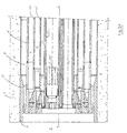
- the present invention thus applies to any burner with at least four ducts 11 ', 15', 4 ', 5' substantially concentric fuel supply and primary combustion air, comprising axial air and the air set in rotation, and a central stabilizer 3 placed at the outlet of a central primary air supply duct 11 ' emerging through openings 13 passing through said stabilizer, these openings can be calibrated holes circular, or slits, or any other shape; which stabilizer overflows in a radial direction relative to any opening 14 of a 10 '' tube placed in said air duct 11 'central primary and inside which can be injected fuel such as a supply rod 10 for a liquid fuel or by pneumatic transport directly in said conduit 10 'for any pulverulent solid fuel such as pulverized combustible waste that we want incinerate; all of said conduits and stabilizer form a nozzle 1 of axis XX '.
- Combustion 2 therefore takes place downstream from the outlet of this nozzle 1 around which the secondary air is supplied.
- a general exterior representation of an example of a burner complete can be viewed according to Figure 1 of the European patent 421,903.
- the nozzle 1 of axis XX 'as described in this patent constitutes a preferred embodiment of the following burner the invention: the peripheral outlet openings 4, 5 of the primary air supply ducts 4 ', 5' are arranged radially outside any duct opening 14, 15 10 ', 15' fuel, either directly through a conduit central 10 ', by a rod 10 located in this central duct 10' or by a 15 'peripheral conduit, into which is sent preferably pulverized coal or any fuel gaseous.
- Said peripheral outlet openings 4, 5 supply the nozzle 1 with axial air and swirling air through at least two concentric 4 ', 5' conduits, and the conduit central 11 ', is partially closed by a stabilizer flame 3 in the form of a flange surrounding the opening 14 through which opens said rod 10.
- Said flame stabilizer 3 can be a plate of circular outer shape matching the inner shape of the central primary air supply duct 11 ′: it comprises the orifices or openings 13 for the passage of part of this primary combustion air which with that possibly supplied by the opening, or additional openings, 6 according to the present invention, represents at most 20% of this air primary in such a way that in the central zone 2 located in downstream of said stabilizer 3, no combustion takes place significant fuel, qualifying said central zone 2 of dead.
- the quantity of primary air which is never null, and sent to said central dead zone 2 is included between 0.1% and 20% of the total primary air and preferably less than 10%, and the proportion of air of primary combustion is between 2 and 10% of the total air combustion and preferably less than 6%.
- the flame stabilizer 3 is preferably offset axially behind the set of openings concentric outlets of primary air and fuels solid or gaseous. This stabilizer 3 is arranged at the end before 10 "tubes inside which can be injected fuel, such as by supply rods 10 liquid fuel which are then slid into these 10 "tubes.
- the axial air outlet opening 5 is that located as radially as possible on the outside of all ducts primary air supply and has an outer edge 8 which protrudes axially forward and constitutes the internal edge of the hub of nozzle 1, the external 5 "tube of this conduit 5 'is itself surrounded by concrete 7 for external protection.
- the axial air outlet opening 5 is constituted by the ends of the walls of the 4 "and 5" tubes which may be, at least for that of the 4 "internal tube, conical in shape divergent and may include partitions of orientation and separation of this axial air into several outlet orifices.
- the radial air outlet opening 4 consists of the ends of the walls of the 15 "and 4" tubes which can be also conical and divergent, has partitions of orientation to create the swirling ejection effect of this air;
- opening 6 of the additional gas supply is performed independently of any other gas supply or in air, through a 6 "tube concentric outside that 10 "inside which all fuel can be injected and whose orifice constitutes said opening 14.
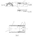
- At least one of the 6 ", 10" tubes constituting said conduit 6 'of additional gas supply is movable relative to the other tube. If the inner 10 "tube is otherwise shrinkage from the 6 'tube, especially when injected direct pulverulent solid fuel into said 10 "tube, this fuel is enriched before it leaves through opening 14; this is represented in all of Figures 7 to 11. According to Figure 11 the opening 6 of the additional gas supply is completely free then that in FIGS. 7 to 10, this opening 6 includes devices 9, 16 for at least partial sealing of said opening :
- the outer tube 6 " delimiting said additional supply duct 6 ' has an inner end flange 16, as the rest Figures 8; this flange allows by moving the inner tube 10 "maximum forward to fully seal this additional opening 6; further back from this flange 16 end allowing total closure, it can be arranged partitions 9 allowing by their inclination inject the additional gas in a guided manner following any desired direction, which then converges anyway towards the inside of the 10 'tube and can be further rotation.
- end of additional supply line 6 ' may have behind partitions 9, a partition circular peripheral 19 surrounding the 10 "outer tube of the conduit 10 'and pierced with radial holes 18 allowing inject additional gas, drawing back the 10 "tube until discovering said orifices; more according to section VIII VIII ' as shown in Figure 8c, this partition peripheral 19 may include notches, plumb or downstream of said orifices 18, so that the gas penetrates preferably through the orifices 18 when they are discovered before the rest of this gas is directed through the partitions 9.
- said inner end flange 16 may include orifices 17 inclined for injecting gas at angles which may be different, as shown particularly in FIGS. 10a to 10c : in particular the section X 1 X ' 1 corresponds to FIG. 10c with a large angle of inclination relative to the axis XX' of the burner, and the section X 2 X ' 2 corresponds to FIG. 10b with an angle d lower inclination.
- FIGS. 3a and 3b in which is also the outer tube 10 "of the conduit 10 ' which is mobile, we have two orientation devices and shutter 9, 16 at least partially of opening 6 such that can be noted in front view according to section IV IV 'of the Figure 3b for the devices inside the duct 6 '; said shutter devices 9 also making it possible to ability to rotate feed stream in additional gas.
- the end of the tube 10 has a flange 16 'located downstream of the outer tube 6 "and whose surface 16" constituting the inner wall of the end of the duct 6 'is shaped divergent conic, which allows on the one hand to orient, in spreading it, the gas flow and on the other hand by variation of the opening X between the respective end edges of the tubes 6 ', 10 "to vary the flow and / or speed of this injection of additional gas.
- said opening 6 for additional gas supply may consist of at least one side by the end of a divergent wall of a tube 6 ", 10", 11 ", said end of said wall being in the form of a divergent truncated cone of angle ⁇ ; each of the walls in this case the 6 ", 10" tubes can form different angles, respectively ⁇ 2, ⁇ 1.
- said opening 6 additional gas supply can be made at less than one side by the end of a converging wall of a tube 6 ", 10", 11 "said end of the wall being shaped truncated cone converging angle ⁇ ; the end of the two said walls can form different angles ⁇ 2, ⁇ 1.
- the burner may include in its central part several fuel supply pipes passing through the central supply pipe 11 ′ in primary air and opening out through the stabilizer 3; it may be at least in part of a conduit 10 '1 is possible to drag a liquid fuel supply rod 10 one on the other at least a conduit 10' to 2 of directly injecting powdered solid fuel therein as indicated above, and finally a conduit 12 constituting in fact the igniter of the burner to start the combustion of the fuels in the other conduits.
- said burner can then comprise as many openings 6 of additional gas supplies as it includes said fuel supply conduits 10 ′, 12; and each of the ends of said conduits can be equipped with one of the devices described in FIGS. 2 to 4 and 7 to 11 knowing that the igniter conduit 12 may not include such an opening 6 for additional gas supply.
- the additional gas supply conduits 6 ′ these being able to contain acid condensable elements such as H 2 SO 4 or HCl, it is important to avoid the excessive cooling and the condensation of these components against the walls of said ducts as they would cause corrosion and their rapid destruction; to avoid this, said walls can be insulated to prevent them from being colder than the temperature of the fuel; for this, it is possible to isolate either the walls of the primary air guide tubes from the guide tubes of the solid or gaseous fuel circuits, or the walls of these latter conduits.
- This thermal insulation can be carried out on the side not subject to abrasion of solid fuel or gas, and preferably consisting of a protective tube of small thickness, approximately 0.5 to 2 mm and either of felt paper or cardboard. insulation with very low thermal coefficient and a thickness of the order of 2 to 15 mm, or by spraying a deposit of special temperature-resistant paint having a thermal coefficient also very low.
- All the devices according to the present invention can apply to any burner with known basic characteristics as described in the introduction and which may include other peripheral circuits (outside and around stabilizer 3) fuel supply in addition to that of pulverized coal 15 'which is the only one represented in the embodiment taken into account example attached.
Landscapes
- Engineering & Computer Science (AREA)
- Chemical & Material Sciences (AREA)
- Combustion & Propulsion (AREA)
- Mechanical Engineering (AREA)
- General Engineering & Computer Science (AREA)
- Pressure-Spray And Ultrasonic-Wave- Spray Burners (AREA)
- Vehicle Body Suspensions (AREA)
- Pre-Mixing And Non-Premixing Gas Burner (AREA)
- Filtering Of Dispersed Particles In Gases (AREA)
Description
Claims (15)
- Brûleur comportant au moins quatre conduits (4', 5', 11', 15') sensiblement concentriques, ces quatre conduits comprenant un conduit central d'alimentation en air primaire (11') dans lequel est placé au moins un tube (10" ) formant un conduit central d'alimentation en combustible (10' ; 10'1 ; 10'2 ; 12), un conduit périphérique d'alimentation en combustible (15') qui est situé à l'extérieur du conduit central d'alimentation en air primaire (11'), un conduit d'alimentation en air primaire à circulation sensiblement axiale (5') qui est situé à l'extérieur de tous les conduits d'alimentation en combustible (10' ; 10'1 ; 10'2 ; 12, 15'), et un conduit d'alimentation en air primaire (4') qui comporte des cloisons d'orientation pour créer un effet tourbillonnant à l'air, et qui est situé à l'extérieur de tous les conduits d'alimentation en combustible (10' ; 10'1 ; 10'2; 12, 15'), le brûleur comportant un stabilisateur central (3) placé à la sortie du conduit central d'alimentation en air primaire (11'), entouré par un tube (11"), comportant des ouvertures (13) au travers desquelles débouche l'air primaire provenant du conduit central d'alimentation en air primaire (11'), et débordant en direction radiale par rapport à toute ouverture centrale d'alimentation en combustible (14) de conduit central d'alimentation en combustible (10'; 10'1; 10'2; 12), caractérisé en ce qu'il comporte au moins une ouverture d'alimentation additionnelle en gaz (6) située à l'extérieur de tout conduit central d'alimentation en combustible (10' ; 10'1 ; 10'2 ; 12) et à l'intérieur du tube (11") entourant le stabilisateur central (3).
- Brûleur selon la revendication 1, caractérisé en ce qu'au moins l'une des ouvertures d'alimentation additionnelle en gaz (6) est alimentée en combustible à partir d'une source d'alimentation en combustible.
- Brûleur selon la revendication 1 ou 2, caractérisé en ce qu'au moins l'une des ouvertures d'alimentation additionnelle en gaz (6) est alimentée en air primaire à partir d'une source d'alimentation en air primaire.
- Brûleur selon la revendication 3, caractérisé en ce que l'ouverture d'au moins une alimentation additionnelle en air primaire (6) est alimentée par le conduit central d'amenée d'air primaire (11').
- Brûleur selon l'une des revendications 1 à 4, caractérisé en ce que l'ouverture d'au moins une alimentation additionnelle en gaz (6) est alimentée par un conduit d'alimentation additionnelle en gaz (6') réalisé indépendamment de tout autre conduit d'alimentation en gaz (4', 5', 10'; 10'1; 10'2; 12, 13', 15') et délimité par un tube additionnel (6").
- Brûleur selon la revendication 5, caractérisé en ce qu'un conduit d'alimentation additionnelle en gaz (6') est délimité par le tube (11") entourant le stabilisateur central (3) et en ce que le tube additionnel (6") est intérieur et concentrique au tube (11" ) entourant le stabilisateur central (3) et délimite le conduit d'alimentation additionnelle en gaz (6') correspondant du conduit central d'alimentation en air primaire (11').
- Brûleur selon la revendication 5 ou 6, caractérisé en ce qu'au moins un conduit d'alimentation additionnelle en gaz (6') est délimité par un tube (10") formant un conduit central d'alimentation en combustible (10';10'1;10'2;12) et en ce que le tube additionnel (6") correspondant est extérieur et concentrique à ce tube (10") formant un conduit central d'alimentation en combustible (10';10'1;10'2;12), et délimite ce conduit d'alimentation additionnelle en gaz (6') du conduit central d'alimentation en combustible (10';10'1;10'2;12) correspondant.
- Brûleur selon l'une des revendications 5 à 7, caractérisé en ce que l'un des tubes (6", 10", 11") délimitant un conduit d'alimentation additionnelle en gaz (6') est mobile par rapport à l'autre tube (10", 11", 6") délimitant ce même conduit d'alimentation additionnelle en gaz (6').
- Brûleur selon l'une des revendications 1 à 8, caractérisé en ce qu'au moins une ouverture d'alimentation additionnelle en gaz (6) comporte des dispositifs (9,16) adaptés à obturer au moins partiellement cette ouverture d'alimentation additionnelle en gaz (6).
- Brûleur selon l'une des revendications 1 à 9, caractérisé en ce que l'extrémité axiale d'au moins un tube (6" , 10" , 11") délimitant un conduit d'alimentation additionnelle en gaz (6') et formant l'ouverture d'alimentation additionnelle en gaz (6) est une paroi en forme de tronc de cône divergent.
- Brûleur selon l'une des revendications 1 à 10, caractérisé en ce que l'extrémité axiale d'au moins un tube (6", 10", 11") délimitant un conduit d'alimentation additionnelle en gaz (6') et formant l'ouverture d'alimentation additionnelle en gaz (6) est une paroi en forme de tronc de cône convergent.
- Brûleur selon l'une des revendications 1 à 11, caractérisé en ce qu'au moins une ouverture d'alimentation additionnelle en gaz (6) comporte des dispositifs (9,17,18) adaptés à guider l'injection du gaz suivant toute direction souhaitée.
- Brûleur selon l'une des revendications 1 à 12, caractérisé en ce que les parois des tubes (6", 10", 11") délimitant l'ensemble des conduits d'alimentation additionnelle en gaz (6') sont thermiquement isolés.
- Brûleur selon l'une des revendication 1 à 13, caractérisé en ce qu'il comporte autant d'alimentation (6) additionnelle en gaz que de conduits centraux d'alimentation en combustible (10' ; 10'1 ; 10'2 ; 12).
- Brûleur selon l'une des revendications 1 à 14, caractérisé en ce que l'air primaire débouchant des orifices (13) et, éventuellement des ouvertures d'alimentation additionnelle en gaz (6), représente au plus 20%, ou même 10%, de l'air primaire.
Applications Claiming Priority (2)
| Application Number | Priority Date | Filing Date | Title |
|---|---|---|---|
| FR9808254 | 1998-06-24 | ||
| FR9808254A FR2780489B1 (fr) | 1998-06-24 | 1998-06-24 | Perfectionnement aux bruleurs comportant au moins trois conduits d'alimentation en air, dont deux axial et en rotation, concentriques avec au moins une alimentation-en combustible, et un stabilisateur central |
Publications (2)
| Publication Number | Publication Date |
|---|---|
| EP0967434A1 EP0967434A1 (fr) | 1999-12-29 |
| EP0967434B1 true EP0967434B1 (fr) | 2004-08-18 |
Family
ID=9528008
Family Applications (1)
| Application Number | Title | Priority Date | Filing Date |
|---|---|---|---|
| EP99430010A Expired - Lifetime EP0967434B1 (fr) | 1998-06-24 | 1999-06-23 | Brûleur à conduits concentriques d'alimentation en air et à stabilisateur central |
Country Status (5)
| Country | Link |
|---|---|
| EP (1) | EP0967434B1 (fr) |
| AT (1) | ATE274171T1 (fr) |
| DE (1) | DE69919456T2 (fr) |
| ES (1) | ES2226315T3 (fr) |
| FR (1) | FR2780489B1 (fr) |
Cited By (2)
| Publication number | Priority date | Publication date | Assignee | Title |
|---|---|---|---|---|
| CN101542204A (zh) * | 2006-11-29 | 2009-09-23 | Fl史密斯公司 | 设有燃料流变向装置的燃烧器 |
| JP2010511141A (ja) * | 2006-11-29 | 2010-04-08 | エフエルシュミッド エー/エス | 解体可能なバーナ |
Families Citing this family (9)
| Publication number | Priority date | Publication date | Assignee | Title |
|---|---|---|---|---|
| FR2823290B1 (fr) | 2001-04-06 | 2006-08-18 | Air Liquide | Procede de combustion comportant des injections separees de combustible et d oxydant et ensemble bruleur pour la mise en oeuvre de ce procede |
| FR2887597B1 (fr) | 2005-06-27 | 2010-04-30 | Egci Pillard | Conduite annulaire et bruleur comportant une telle conduite |
| FR2888899A1 (fr) | 2005-07-21 | 2007-01-26 | Egci Pillard Sa | Ensemble de conduites annulaires et bruleur comprenant un tel ensemble |
| FR2901852B1 (fr) * | 2006-05-30 | 2010-10-22 | Egci Pillard | Conduite annulaire a double flux et bruleur comportant une telle conduite |
| FR2919043A1 (fr) * | 2007-07-20 | 2009-01-23 | Pillard Chauffage | Bruleur comportant une conduite annulaire d'alimentation en air |
| FR2930626B1 (fr) * | 2008-04-28 | 2010-05-21 | Fives Pillard | Bruleur a points peripheriques d'injection d'air a flux axial |
| AT510439B1 (de) | 2010-10-29 | 2012-04-15 | Unitherm Cemcon Feuerungsanlagen Gesellschaft M B | Vorrichtung zum fördern von pneumatisch geförderten brennstoffen |
| CN102012024A (zh) * | 2010-11-12 | 2011-04-13 | 新兴能源装备有限公司 | 一种活性石灰回转窑发生炉的煤气燃烧器 |
| FR3024765B1 (fr) * | 2014-08-06 | 2016-07-29 | Fives Pillard | Bruleur a injection d'air ou de gaz ajustable |
Family Cites Families (5)
| Publication number | Priority date | Publication date | Assignee | Title |
|---|---|---|---|---|
| GB1537037A (en) * | 1976-03-17 | 1978-12-29 | Nu Way Heating Plants Ltd | Burners for fluid fuels |
| US4208180A (en) * | 1978-02-06 | 1980-06-17 | Ube Industries, Ltd. | Mixed-firing burners for use with pulverized coal and heavy oil |
| DE3518080A1 (de) * | 1985-05-20 | 1986-11-20 | Stubinen Utveckling AB, Stockholm | Verfahren und vorrichtung zum verbrennen fluessiger und/oder fester brennstoffe in pulverisierter form |
| DE3933050C2 (de) | 1989-10-04 | 2000-06-15 | Pillard Feuerungen Gmbh | Verfahren zum Betreiben eines Brenners für Drehrohröfen und Brenner hierfür |
| DK173204B1 (da) * | 1997-03-07 | 2000-03-13 | F.L.Smidth & Co A/S | r i en ovn Fremgangsmaede og braender til at indfoere braende |
-
1998
- 1998-06-24 FR FR9808254A patent/FR2780489B1/fr not_active Expired - Fee Related
-
1999
- 1999-06-23 EP EP99430010A patent/EP0967434B1/fr not_active Expired - Lifetime
- 1999-06-23 AT AT99430010T patent/ATE274171T1/de not_active IP Right Cessation
- 1999-06-23 DE DE69919456T patent/DE69919456T2/de not_active Expired - Fee Related
- 1999-06-23 ES ES99430010T patent/ES2226315T3/es not_active Expired - Lifetime
Cited By (3)
| Publication number | Priority date | Publication date | Assignee | Title |
|---|---|---|---|---|
| CN101542204A (zh) * | 2006-11-29 | 2009-09-23 | Fl史密斯公司 | 设有燃料流变向装置的燃烧器 |
| JP2010511141A (ja) * | 2006-11-29 | 2010-04-08 | エフエルシュミッド エー/エス | 解体可能なバーナ |
| CN101542204B (zh) * | 2006-11-29 | 2012-12-26 | Fl史密斯公司 | 设有燃料流变向装置的燃烧器 |
Also Published As
| Publication number | Publication date |
|---|---|
| DE69919456T2 (de) | 2005-03-10 |
| FR2780489A1 (fr) | 1999-12-31 |
| FR2780489B1 (fr) | 2000-09-08 |
| DE69919456D1 (de) | 2004-09-23 |
| ATE274171T1 (de) | 2004-09-15 |
| ES2226315T3 (es) | 2005-03-16 |
| EP0967434A1 (fr) | 1999-12-29 |
Similar Documents
| Publication | Publication Date | Title |
|---|---|---|
| EP0334736B1 (fr) | Brûleurs à gaz | |
| EP1873458B1 (fr) | Agencement pour chambre de combustion de turbomachine ayant un déflecteur à collerette | |
| FR2536465A1 (fr) | Ensemble d'injecteur de combustible a air souffle | |
| CA2593179C (fr) | Dispositif d'injection d'un melange d'air et de carburant, chambre de combustion et turbomachine munies d'un tel dispositif | |
| FR2931203A1 (fr) | Injecteur de carburant pour turbine a gaz et son procede de fabrication | |
| EP0200644A1 (fr) | Procédé pour la combustion de combustibles fluides et brûleur à turbulence adapté à sa mise en oeuvre | |
| EP2071242A1 (fr) | Système d'injection d'un mélange d'air et de carburant dans une chambre de combustion de turbomachine | |
| FR2585770A1 (fr) | Dispositif d'injection a bol elargi pour chambre de combustion de turbomachine | |
| EP0222654B1 (fr) | Turboréacteur à post-combustion à injecteurs de post-combustion radiaux individuels | |
| EP0967434A1 (fr) | Brûleur à conduits concentriques d'alimentation en air et à stabilisateur central | |
| FR2621650A1 (fr) | Assemblage d'injecteur de carburant pour moteur a turbine a gaz | |
| FR2579722A1 (fr) | Procede pour l'atomisation de combustible et dispositif pour la mise en oeuvre de ce procede | |
| EP1770333B1 (fr) | Bras d'injecteur anti-cokéfaction | |
| EP1074790B1 (fr) | Brûleur à recirculation de fumées | |
| FR2942640A1 (fr) | Chambre de post-combustion pour turbomachine | |
| EP1016828B1 (fr) | Injecteur pour brûleur et système d'injection correspondant | |
| FR2943119A1 (fr) | Systemes d'injection de carburant dans une chambre de combustion de turbomachine | |
| FR2779805A1 (fr) | Injecteur de combustible sous forme de brouillard pour bruleur a fioul et bruleur muni d'un tel injecteur | |
| CA1110920A (fr) | Procede et dispositif pour l'incineration des boues | |
| FR2772887A1 (fr) | Bruleur a faible emission d'oxyde d'azote avec circuit de gaz recycle | |
| EP2771619B1 (fr) | Chambre de combustion annulaire dans une turbomachine | |
| FR2498301A1 (fr) | Procede, appareil et injecteur pour bruler une matiere contenant des hydrocarbures avec reduction des fumees | |
| FR2873168A1 (fr) | Turboreacteur comprenant une chambre de post-combustion a allumage securise | |
| FR2549579A1 (fr) | Bruleur a gaz pour pistolet de metallisation | |
| EP1045203B1 (fr) | Brûleur à plusieurs combustibles |
Legal Events
| Date | Code | Title | Description |
|---|---|---|---|
| PUAI | Public reference made under article 153(3) epc to a published international application that has entered the european phase |
Free format text: ORIGINAL CODE: 0009012 |
|
| AK | Designated contracting states |
Kind code of ref document: A1 Designated state(s): AT DE DK ES GB IT |
|
| AX | Request for extension of the european patent |
Free format text: AL;LT;LV;MK;RO;SI |
|
| 17P | Request for examination filed |
Effective date: 20000410 |
|
| AKX | Designation fees paid |
Free format text: AT DE DK ES GB IT |
|
| 17Q | First examination report despatched |
Effective date: 20020412 |
|
| GRAP | Despatch of communication of intention to grant a patent |
Free format text: ORIGINAL CODE: EPIDOSNIGR1 |
|
| GRAS | Grant fee paid |
Free format text: ORIGINAL CODE: EPIDOSNIGR3 |
|
| GRAA | (expected) grant |
Free format text: ORIGINAL CODE: 0009210 |
|
| AK | Designated contracting states |
Kind code of ref document: B1 Designated state(s): AT DE DK ES GB IT |
|
| PG25 | Lapsed in a contracting state [announced via postgrant information from national office to epo] |
Ref country code: GB Free format text: LAPSE BECAUSE OF FAILURE TO SUBMIT A TRANSLATION OF THE DESCRIPTION OR TO PAY THE FEE WITHIN THE PRESCRIBED TIME-LIMIT Effective date: 20040818 |
|
| REG | Reference to a national code |
Ref country code: GB Ref legal event code: FG4D Free format text: NOT ENGLISH |
|
| REF | Corresponds to: |
Ref document number: 69919456 Country of ref document: DE Date of ref document: 20040923 Kind code of ref document: P |
|
| PG25 | Lapsed in a contracting state [announced via postgrant information from national office to epo] |
Ref country code: DK Free format text: LAPSE BECAUSE OF FAILURE TO SUBMIT A TRANSLATION OF THE DESCRIPTION OR TO PAY THE FEE WITHIN THE PRESCRIBED TIME-LIMIT Effective date: 20041118 |
|
| REG | Reference to a national code |
Ref country code: ES Ref legal event code: FG2A Ref document number: 2226315 Country of ref document: ES Kind code of ref document: T3 |
|
| GBV | Gb: ep patent (uk) treated as always having been void in accordance with gb section 77(7)/1977 [no translation filed] |
Effective date: 20040818 |
|
| PLBE | No opposition filed within time limit |
Free format text: ORIGINAL CODE: 0009261 |
|
| STAA | Information on the status of an ep patent application or granted ep patent |
Free format text: STATUS: NO OPPOSITION FILED WITHIN TIME LIMIT |
|
| 26N | No opposition filed |
Effective date: 20050519 |
|
| PGFP | Annual fee paid to national office [announced via postgrant information from national office to epo] |
Ref country code: IT Payment date: 20060630 Year of fee payment: 8 |
|
| PGFP | Annual fee paid to national office [announced via postgrant information from national office to epo] |
Ref country code: AT Payment date: 20090630 Year of fee payment: 11 |
|
| PG25 | Lapsed in a contracting state [announced via postgrant information from national office to epo] |
Ref country code: IT Free format text: LAPSE BECAUSE OF NON-PAYMENT OF DUE FEES Effective date: 20070623 |
|
| PGFP | Annual fee paid to national office [announced via postgrant information from national office to epo] |
Ref country code: ES Payment date: 20090713 Year of fee payment: 11 |
|
| PGFP | Annual fee paid to national office [announced via postgrant information from national office to epo] |
Ref country code: DE Payment date: 20090626 Year of fee payment: 11 |
|
| PG25 | Lapsed in a contracting state [announced via postgrant information from national office to epo] |
Ref country code: DE Free format text: LAPSE BECAUSE OF NON-PAYMENT OF DUE FEES Effective date: 20110101 |
|
| PG25 | Lapsed in a contracting state [announced via postgrant information from national office to epo] |
Ref country code: AT Free format text: LAPSE BECAUSE OF NON-PAYMENT OF DUE FEES Effective date: 20100623 |
|
| REG | Reference to a national code |
Ref country code: ES Ref legal event code: FD2A Effective date: 20110715 |
|
| PG25 | Lapsed in a contracting state [announced via postgrant information from national office to epo] |
Ref country code: ES Free format text: LAPSE BECAUSE OF NON-PAYMENT OF DUE FEES Effective date: 20110705 |
|
| PG25 | Lapsed in a contracting state [announced via postgrant information from national office to epo] |
Ref country code: ES Free format text: LAPSE BECAUSE OF NON-PAYMENT OF DUE FEES Effective date: 20100624 |