EP0967006A2 - Apparatus for the catalytic reaction of a fluid in the gas phase - Google Patents
Apparatus for the catalytic reaction of a fluid in the gas phase Download PDFInfo
- Publication number
- EP0967006A2 EP0967006A2 EP99111405A EP99111405A EP0967006A2 EP 0967006 A2 EP0967006 A2 EP 0967006A2 EP 99111405 A EP99111405 A EP 99111405A EP 99111405 A EP99111405 A EP 99111405A EP 0967006 A2 EP0967006 A2 EP 0967006A2
- Authority
- EP
- European Patent Office
- Prior art keywords
- catalyst bed
- catalyst
- bed
- katalysatorbett
- das
- Prior art date
- Legal status (The legal status is an assumption and is not a legal conclusion. Google has not performed a legal analysis and makes no representation as to the accuracy of the status listed.)
- Granted
Links
Images


Classifications
-
- B—PERFORMING OPERATIONS; TRANSPORTING
- B01—PHYSICAL OR CHEMICAL PROCESSES OR APPARATUS IN GENERAL
- B01J—CHEMICAL OR PHYSICAL PROCESSES, e.g. CATALYSIS OR COLLOID CHEMISTRY; THEIR RELEVANT APPARATUS
- B01J8/00—Chemical or physical processes in general, conducted in the presence of fluids and solid particles; Apparatus for such processes
- B01J8/02—Chemical or physical processes in general, conducted in the presence of fluids and solid particles; Apparatus for such processes with stationary particles, e.g. in fixed beds
- B01J8/04—Chemical or physical processes in general, conducted in the presence of fluids and solid particles; Apparatus for such processes with stationary particles, e.g. in fixed beds the fluid passing successively through two or more beds
- B01J8/0492—Feeding reactive fluids
-
- B—PERFORMING OPERATIONS; TRANSPORTING
- B01—PHYSICAL OR CHEMICAL PROCESSES OR APPARATUS IN GENERAL
- B01J—CHEMICAL OR PHYSICAL PROCESSES, e.g. CATALYSIS OR COLLOID CHEMISTRY; THEIR RELEVANT APPARATUS
- B01J8/00—Chemical or physical processes in general, conducted in the presence of fluids and solid particles; Apparatus for such processes
- B01J8/02—Chemical or physical processes in general, conducted in the presence of fluids and solid particles; Apparatus for such processes with stationary particles, e.g. in fixed beds
- B01J8/04—Chemical or physical processes in general, conducted in the presence of fluids and solid particles; Apparatus for such processes with stationary particles, e.g. in fixed beds the fluid passing successively through two or more beds
- B01J8/0403—Chemical or physical processes in general, conducted in the presence of fluids and solid particles; Apparatus for such processes with stationary particles, e.g. in fixed beds the fluid passing successively through two or more beds the fluid flow within the beds being predominantly horizontal
- B01J8/0407—Chemical or physical processes in general, conducted in the presence of fluids and solid particles; Apparatus for such processes with stationary particles, e.g. in fixed beds the fluid passing successively through two or more beds the fluid flow within the beds being predominantly horizontal through two or more cylindrical annular shaped beds
- B01J8/0411—Chemical or physical processes in general, conducted in the presence of fluids and solid particles; Apparatus for such processes with stationary particles, e.g. in fixed beds the fluid passing successively through two or more beds the fluid flow within the beds being predominantly horizontal through two or more cylindrical annular shaped beds the beds being concentric
-
- B—PERFORMING OPERATIONS; TRANSPORTING
- B01—PHYSICAL OR CHEMICAL PROCESSES OR APPARATUS IN GENERAL
- B01J—CHEMICAL OR PHYSICAL PROCESSES, e.g. CATALYSIS OR COLLOID CHEMISTRY; THEIR RELEVANT APPARATUS
- B01J8/00—Chemical or physical processes in general, conducted in the presence of fluids and solid particles; Apparatus for such processes
- B01J8/02—Chemical or physical processes in general, conducted in the presence of fluids and solid particles; Apparatus for such processes with stationary particles, e.g. in fixed beds
- B01J8/04—Chemical or physical processes in general, conducted in the presence of fluids and solid particles; Apparatus for such processes with stationary particles, e.g. in fixed beds the fluid passing successively through two or more beds
- B01J8/0446—Chemical or physical processes in general, conducted in the presence of fluids and solid particles; Apparatus for such processes with stationary particles, e.g. in fixed beds the fluid passing successively through two or more beds the flow within the beds being predominantly vertical
- B01J8/0461—Chemical or physical processes in general, conducted in the presence of fluids and solid particles; Apparatus for such processes with stationary particles, e.g. in fixed beds the fluid passing successively through two or more beds the flow within the beds being predominantly vertical in two or more cylindrical annular shaped beds
- B01J8/0465—Chemical or physical processes in general, conducted in the presence of fluids and solid particles; Apparatus for such processes with stationary particles, e.g. in fixed beds the fluid passing successively through two or more beds the flow within the beds being predominantly vertical in two or more cylindrical annular shaped beds the beds being concentric
-
- C—CHEMISTRY; METALLURGY
- C10—PETROLEUM, GAS OR COKE INDUSTRIES; TECHNICAL GASES CONTAINING CARBON MONOXIDE; FUELS; LUBRICANTS; PEAT
- C10L—FUELS NOT OTHERWISE PROVIDED FOR; NATURAL GAS; SYNTHETIC NATURAL GAS OBTAINED BY PROCESSES NOT COVERED BY SUBCLASSES C10G OR C10K; LIQUIFIED PETROLEUM GAS; USE OF ADDITIVES TO FUELS OR FIRES; FIRE-LIGHTERS
- C10L3/00—Gaseous fuels; Natural gas; Synthetic natural gas obtained by processes not covered by subclass C10G, C10K; Liquefied petroleum gas
- C10L3/06—Natural gas; Synthetic natural gas obtained by processes not covered by C10G, C10K3/02 or C10K3/04
- C10L3/10—Working-up natural gas or synthetic natural gas
Definitions
- the invention relates to a device in Preamble of claim 1 specified genus.
- Fluids such as the desulfurization of hydrocarbons, here is desulfurization as an example of natural gas called, where two catalysts in the direction of flow of the fluid are connected in series, in many cases the first catalyst in the direction of flow has a shorter lifespan than the second.
- any organic sulfur compounds that are present are converted into H 2 S with the addition of hydrogen.
- the H 2 S is absorbed in a zinc bed, the catalyst volume in the first stage being considerably smaller than in the second stage. It is known to accommodate both catalysts within a common reactor pressure vessel, with a first manhole provided in the dome of the reactor for exchanging the first catalyst and a second manhole provided in the lateral outer jacket opening up a space from which, due to the different useful times second catalyst can then be removed for replacement.
- a disadvantage of this construction is that, for example, this second space between the two catalyst beds cannot be used.
- the US-4 830 843 is a heat exchanger reformer, which is equipped with a burner for the heat balance compensation for the conversion of natural gas and steam into H 2 - and CO 2 -containing gas mixture, which delivers a hot flue gas, which in the indirect heat exchange gives off the heat to the process gas.
- the reactor described in US-3 620 685 is for one Oxidehydro process determined. On the one hand, this requires large inflow areas of the catalyst layers and on the other hand high exhaust gas flow rates after completion catalytic treatment.
- US-3 817 716 describes the treatment of exhaust gases containing higher hydrocarbons and aerosols
- US-3 544 264 shows an exhaust gas catalytic converter system for motor vehicles for the reduction of pollutants such as NO x and CO.
- the invention is based on the object, in addition avoiding the disadvantages described above Device with two different catalyst beds To design life so that the catalysts are independent can be exchanged from one another without having to accept unused dead spaces and with the possibility of any bed to be able to drive around.
- the first and second catalyst beds essentially cylindrical are formed, the cylindrical boundary wall the cylindrical catalyst bed of the inner Forms the inner wall of the second catalyst bed and the first Radial catalyst bed and the second catalyst bed is axially flowable.
- the design propagated here additionally makes possible, for example, the first catalyst bed radial and the second catalyst bed axially designed to be flowable, but of course it is also possible is flow through both catalyst beds axially or radially to train.
- a supply nozzle can be used to the inner first catalyst bed provided with a dome be provided and / or a second feed pipe for bypassing of the first catalyst.
- the inner catalyst bed is flowed through from the outside to the inside and, as already explained above, lies the feed in an upper dome above the first catalyst bed, so becomes the fluid flowing through the first catalyst bed usually discharged via a central manifold, the expediently flows into the upper cathedral, so that to apply the second catalyst bed from above.
- the centric inner drain pipe functional from the entire housing lead out, so that the first catalyst bed can continue to operate if, for example, the second Catalyst bed to be bypassed.
- the reactor generally designated 1 consists of a pressure vessel 2 with an inlet nozzle 3 in the upper dome and an outlet nozzle 4 in the lower dome and a manhole 5 between an upper catalyst bed 6 and a lower catalyst bed 7.
- the upper catalyst bed can, for example the Co-Mo catalyst for the conversion of organic sulfur compounds into H 2 S and the lower catalyst bed the ZnO catalyst for the absorption of the sulfur from H 2 S.
- the upper catalyst bed rests on a support grate 8, under this support grate 8 there is a catalyst-free space 9, into which the connector of the manhole 5 opens, for example the upper catalyst can be changed via the supply connector 3, the lower one via the manhole 5.
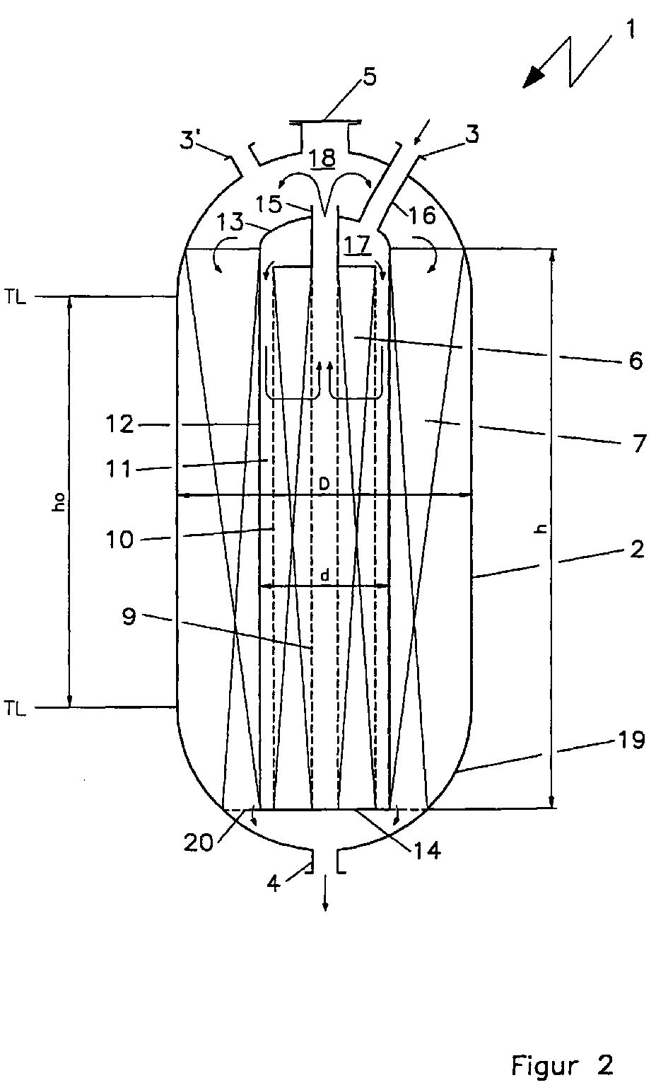
- Fig. 1 are general height information of the catalyst beds the dead space 9 and other dimensions specified, whose equivalent is also given in Fig. 2, the corresponding Dimensions are as an example in a table below reproduced.
- the reactor 1 consists of a pressure vessel 2 with an inlet nozzle 3 and an outlet nozzle 4 for the fluid to be treated.
- a manhole 5 is centered, being inside the Housing 2 arranged a second cylindrical housing 12 which is centrally a perforated cylinder 9 or an outflow pipe 9 and therefore a perforated centrically further outside Contains tube 10, the space between the perforated Tubes 9 and 10 form the first catalyst bed 6.
- the outer wall 12 of this first catalyst vessel forms the inner wall for the second catalyst 7, in which illustrated example the first catalyst bed radially and arranged to flow axially through the second catalyst bed 7 is, without the invention being limited thereto.
- the dome 13 of the housing of the first catalyst bed 6 is penetrated by a perforated central tube 9 with a nozzle 15, the first catalyst housing 12 at the bottom End is completed with a bottom plate 14 which in the Support grid designated 20 for the second catalyst bed transforms.
- the mode of operation of the device according to the invention is based on the flow path of the fluid to be treated, the following:
- the gas to be treated is fed to the nozzle 3 and arrives via a line 16 in a first distributor or Dome space 17 and then into an inflow gap 11 in order then over the perforated wall 10 the first catalyst or to flow radially through the first catalyst bed 6, i.e. here from the outside in.
- the gas Via the perforated central tube 9 through the delivery port 15, the gas enters the second distributor or dome space 18 above the second catalyst bed 7 to penetrate from there, to flow axially and over the support ring 20 to Dispensing nozzle 4 to reach the bottom 19 of the reactor vessel 2 is arranged.
- a second feed pipe 3 ' is also immediate shown in the second distribution space 18.
- the gas be initiated such that it is only the second catalyst bed flows through, then around the first catalyst bed 6 easy to drive around.
- the possibility of the delivery nozzle is not shown 15 in the second cathedral space 18, if necessary, to the outside to continue using the first catalyst to be able to, for example, the second catalyst bed should be avoided.
Landscapes
- Chemical & Material Sciences (AREA)
- Organic Chemistry (AREA)
- Chemical Kinetics & Catalysis (AREA)
- Oil, Petroleum & Natural Gas (AREA)
- Physics & Mathematics (AREA)
- Fluid Mechanics (AREA)
- Engineering & Computer Science (AREA)
- General Chemical & Material Sciences (AREA)
- Devices And Processes Conducted In The Presence Of Fluids And Solid Particles (AREA)
- Organic Low-Molecular-Weight Compounds And Preparation Thereof (AREA)
- Catalysts (AREA)
- Physical Or Chemical Processes And Apparatus (AREA)
Abstract
Mit einer Vorrichtung zur Durchführung katalytischer chemischer Reaktionen eines Fluids in der Gasphase, soll neben der Vermeidung der bekannten Nachteile eine Vorrichtung mit zwei Katalysatorbetten unterschiedlicher Lebensdauer so gestaltet werden, daß die Katalysatoren unabhängig voneinander gewechselt werden können, ohne Inkaufnahme ungenutzter Toträume und mit der Möglichkeit, jedes Bett umfahren zu können.With a device for carrying out catalytic chemical Reactions of a fluid in the gas phase are said to be alongside avoiding the known disadvantages of having a device two catalyst beds with different lifetimes be designed so that the catalysts are independent of each other can be changed without accepting unused Dead spaces and with the ability to drive around every bed to be able to.
Dies wird dadurch erreicht, daß
Description
Die Erfindung richtet sich auf eine Vorrichtung der im
Oberbegriff des Anspruches 1 angegebenen Gattung.The invention relates to a device in
Preamble of
Es gibt eine Reihe katalytischer chemischer Reaktionen eines Fluids, wie beispielsweise der Entschwefelung von Kohlenwasserstoffen, hier sei als Beispiel die Entschwefelung von Erdgas genannt, bei denen zwei Katalysatoren in Strömungsrichtung des Fluids hintereinander geschaltet sind, wobei in vielen Fällen der in Strömungsrichtung erste Katalysator eine kürzere Lebensdauer aufweist als der zweite.There are a number of catalytic chemical reactions one Fluids, such as the desulfurization of hydrocarbons, here is desulfurization as an example of natural gas called, where two catalysts in the direction of flow of the fluid are connected in series, in many cases the first catalyst in the direction of flow has a shorter lifespan than the second.
So werden beispielsweise in einer ersten Stufe etwa vorhandene organische Schwefelverbindungen unter Zugabe von Wasserstoff in H2S umgewandelt. In einer zweiten Stufe wird das H2S in einem Zink-Bett absorbiert, wobei das Katalysatorvolumen der ersten Stufe erheblich kleiner ist als in der zweiten Stufe. Dabei ist es bekannt, beide Katalysatoren innerhalb eines gemeinsamen Reaktordruckgefäßes unterzubringen, wobei schon wegen der unterschiedlichen Nutzzeiten in der Regel ein im Dom des Reaktors vorgesehenes erstes Mannloch zum Austausch des ersten Katalysators und ein im seitlichen Außenmantel vorgesehenes zweites Mannloch einen Raum erschließt, aus dem der zweite Katalysator dann zum Wechsel entnommen werden kann. Nachteilig an dieser Konstruktion ist, daß beispielsweise dieser zweite Raum zwischen den beiden Katalysatorbetten nicht benutzt werden kann.In a first stage, for example, any organic sulfur compounds that are present are converted into H 2 S with the addition of hydrogen. In a second stage, the H 2 S is absorbed in a zinc bed, the catalyst volume in the first stage being considerably smaller than in the second stage. It is known to accommodate both catalysts within a common reactor pressure vessel, with a first manhole provided in the dome of the reactor for exchanging the first catalyst and a second manhole provided in the lateral outer jacket opening up a space from which, due to the different useful times second catalyst can then be removed for replacement. A disadvantage of this construction is that, for example, this second space between the two catalyst beds cannot be used.
Zum im weitesten Sinne hier betroffenen Stand der Technik sei beispielsweise auf die EP-0 400 698-A1 oder die US-3 544 264, US-3 817 716, US-3 620 685 oder US-4 830 834 verwiesen. Bei der Vorrichtung aus der oben genannten europäischen Anmeldung handelt es sich um einen Konverter, der vorzugsweise für die Behandlung staubhaltiger Gase verwendet werden soll. Dabei werden in der Vorzugsausführung zwei Katalysatorbetten eingesetzt.The state of the art concerned here in the broadest sense be for example on EP-0 400 698-A1 or US-3 544,264, U.S. 3,817,716, U.S. 3,620,685 or U.S. 4,830,834 referred. In the device from the above European Registration is a converter that preferably used for the treatment of dusty gases shall be. In the preferred version, two Catalyst beds used.
Bei der US-4 830 843 handelt es sich um einen Wärmetauscher-Reformer, der zum Wärmebilanzausgleich für die Umwandlung von Erdgas und Dampf in H2- und CO2-haltiges Gasgemisch mit einem Brenner ausgerüstet ist, der ein heißes Rauchgas liefert, welches im indirekten Wärmetausch die Wärme an das Prozeßgas abgibt.The US-4 830 843 is a heat exchanger reformer, which is equipped with a burner for the heat balance compensation for the conversion of natural gas and steam into H 2 - and CO 2 -containing gas mixture, which delivers a hot flue gas, which in the indirect heat exchange gives off the heat to the process gas.
Der in der US-3 620 685 beschriebene Reaktor ist für einen Oxidehydro-Prozeß bestimmt. Dieser erfordert einerseits große Anströmflächen der Katalysatorschichten und andererseits hohe Abgasströmgeschwindigkeiten nach abgeschlossener katalytischer Behandlung. The reactor described in US-3 620 685 is for one Oxidehydro process determined. On the one hand, this requires large inflow areas of the catalyst layers and on the other hand high exhaust gas flow rates after completion catalytic treatment.
Die US-3 817 716 beschreibt die Behandlung von Abgasen, die höhere Kohlenwasserstoffe und Aerosole enthalten, wobei schließlich die US-3 544 264 ein Abgaskatalysatorsystem für Kraftfahrzeuge zur Reduzierung von Schadstoffen, wie NOx und CO zeigt.US-3 817 716 describes the treatment of exhaust gases containing higher hydrocarbons and aerosols, and finally US-3 544 264 shows an exhaust gas catalytic converter system for motor vehicles for the reduction of pollutants such as NO x and CO.
Der Erfindung liegt demgegenüber die Aufgabe zugrunde, neben der Vermeidung der oben beschriebenen Nachteile eine Vorrichtung mit zwei Katalysatorbetten unterschiedlicher Lebensdauer so zu gestalten, daß die Katalysatoren unabhängig voneinander gewechselt werden können, ohne Inkaufnahme ungenutzter Toträume und mit der Möglichkeit, jedes Bett umfahren zu können.The invention is based on the object, in addition avoiding the disadvantages described above Device with two different catalyst beds To design life so that the catalysts are independent can be exchanged from one another without having to accept unused dead spaces and with the possibility of any bed to be able to drive around.
Mit einer Vorrichtung der eingangs bezeichneten Art wird diese Aufgabe gemäß der Erfindung dadurch gelöst, daß das im Strömungsweg erste Katalysatorbett ein kleineres Katalysatorvolumen aufweist als das zweite Katalysatorbett, das erste und zweite Katalysatorbett im wesentlichen zylindrisch ausgebildet sind, wobei die zylindrische Begrenzungswand des inneren Katalysatorbettes die zylindrische Innenwand des zweiten Katalysatorbettes bildet und das erste Katalysatorbett radial und das zweite Katalysatorbett axial durchströmbar ist.With a device of the type described in the introduction solved this problem according to the invention in that the a smaller catalyst volume in the first catalyst bed flow path than the second catalyst bed, the first and second catalyst beds essentially cylindrical are formed, the cylindrical boundary wall the cylindrical catalyst bed of the inner Forms the inner wall of the second catalyst bed and the first Radial catalyst bed and the second catalyst bed is axially flowable.
Dadurch, daß das erste Katalysatorbett vom zweiten Katalysatorbett umgeben ist, ist es möglich, beide Katalysatoren funktionsmäßig durch das gleiche Mannloch etwa im Dom eines Reaktorgefäßes unabhängig voneinander zu wechseln.Characterized in that the first catalyst bed from the second catalyst bed is surrounded, it is possible to use both catalysts functionally through the same manhole in the cathedral of one To change the reactor vessel independently.
Weitere Vorteile der Erfindung ergeben sich aufgrund der Unteransprüche, wobei die hier propagierte Gestaltung es zusätzlich möglich macht, das erste Katalysatorbett beispielsweise radial und das zweite Katalysatorbett axial durchströmbar zu gestalten, wobei es natürlich auch möglich ist, beide Katalysatorbetten axial oder radial durchströmbar auszubilden.Further advantages of the invention result from the Subclaims, the design propagated here additionally makes possible, for example, the first catalyst bed radial and the second catalyst bed axially designed to be flowable, but of course it is also possible is flow through both catalyst beds axially or radially to train.
Vorteilhaft ist es, wenn die Abmessungen der Aufnahmen für das kleinere erste Katalysatorbett und das größere zweite Katalysatorbett so aufeinander abgestimmt sind, daß die Füllhöhen beider Katalysatorbetten im Gesamtgehäuse des Katalysators im wesentlichen identisch sind, wie dies die Erfindung ebenfalls vorsieht.It is advantageous if the dimensions of the recordings for the smaller first catalyst bed and the larger second The catalyst bed are coordinated so that the Filling levels of both catalyst beds in the overall housing of the Catalyst are essentially identical to this Invention also provides.
Im Dom des Gesamtkatalysatorgehäuses kann ein Zufuhrstutzen zum mit einem Dom versehenen inneren ersten Katalysatorbett vorgesehen sein und/oder ein zweiter Zufuhrstutzen zur Umfahrung des ersten Katalysators.In the dome of the entire catalytic converter housing, a supply nozzle can be used to the inner first catalyst bed provided with a dome be provided and / or a second feed pipe for bypassing of the first catalyst.
Wird das innere Katalysatorbett von außen nach innen durchströmt und liegt, wie oben schon ausgeführt, die Zuführung in einem oberen Dom oberhalb des ersten Katalysatorbettes, so wird das das erste Katalysatorbett durchströmende Fluid in der Regel über ein zentrisches Sammelrohr abgeführt, das zweckmäßig innerhalb des oberen Doms mündet, um so das zweite Katalysatorbett von oben zu beaufschlagen. Bei einer solchen Konstruktion kann auch vorgesehen sein, das zentrische innere Abströmrohr funktionsmäßig aus dem Gesamtgehäuse herauszuführen, so daß auch das erste Katalysatorbett weiterbetrieben werden kann, wenn beispielsweise das zweite Katalysatorbett umfahren werden soll.The inner catalyst bed is flowed through from the outside to the inside and, as already explained above, lies the feed in an upper dome above the first catalyst bed, so becomes the fluid flowing through the first catalyst bed usually discharged via a central manifold, the expediently flows into the upper cathedral, so that to apply the second catalyst bed from above. At a such a construction can also be provided, the centric inner drain pipe functional from the entire housing lead out, so that the first catalyst bed can continue to operate if, for example, the second Catalyst bed to be bypassed.
Die Erfindung ist nachstehend anhand der Zeichnung beispielsweise näher erläutert. Diese zeigt in
- Fig. 1
- einen entsprechenden Reaktor nach dem Stand der Technik und in
- Fig. 2
- eine Vorrichtung nach der Erfindung.
- Fig. 1
- a corresponding reactor according to the prior art and in
- Fig. 2
- a device according to the invention.
Der allgemein mit 1 bezeichnete Reaktor nach dem Stand der
Technik besteht aus einem Druckgefäß 2 mit einem Eintrittsstutzen
3 im oberen Dom und einem Austrittsstutzen 4 im
unteren Dom sowie einem Mannloch 5 zwischen einem oberen
Katalysatorbett 6 und einem unteren Katalysatorbett 7. Das
obere Katalysatorbett kann beispielsweise den Co-Mo-Katalysator
zur Umwandlung organischer Schwefelverbindungen in H2S
und das untere Katalysatorbett den ZnO-Katalysator zur Absorption
des Schwefels aus H2S darstellen. Das obere Katalysatorbett
ruht auf einem Tragrost 8, unter diesem Tragrost
8 befindet sich ein katalysatorfreier Raum 9, in den der
Stutzen des Mannloches 5 mündet, wobei beispielsweise der
obere Katalysator über den Zufuhrstutzen 3 gewechselt werden
kann, der untere über das Mannloch 5.The reactor generally designated 1 according to the prior art consists of a
In Fig. 1 sind allgemeine Höhenangaben der Katalysatorbetten
des Totraumes 9 sowie weitere Abmessungen angegeben,
deren Äquivalent auch in Fig. 2 angegeben ist, die entsprechenden
Maße sind als Beispiel in einer Tabelle weiter unten
wiedergegeben.In Fig. 1 are general height information of the catalyst beds
the
Soweit wie möglich, sind in Fig. 2, die die erfindungsgemäße Vorrichtung darstellt, die gleichen Bezugszeichen gewählt, wie bei der Beschreibung des Standes der Technik nach Fig. 1.As far as possible, are in Fig. 2, the inventive Device, chosen the same reference numerals, as in the description of the prior art according to Fig. 1.
So besteht dort der Reaktor 1 aus einem Druckgefäß 2 mit
einem Eintrittsstutzen 3 und einem Austrittsstutzen 4 für
das zu behandelnde Fluid. Im Dom des Druckgefäßes 2 befindet
sich zentrisch ein Mannloch 5, wobei im Inneren des
Gehäuses 2 ein zweites zylindrisches Gehäuse 12 angeordnet
ist, welches zentrisch einen perforierten Zylinder 9 bzw.
ein Abströmrohr 9 und darum zentrisch weiter außen ein perforiertes
Rohr 10 enthält, wobei der Raum zwischen den perforierten
Rohren 9 und 10 das erste Katalysatorbett 6 bildet.
Die Außenwand 12 dieses ersten Katalysatorgefäßes bildet
die Innenwand für den zweiten Katalysator 7, wobei im
dargestellten Beispiel das erste Katalysatorbett radial und
das zweite Katalysatorbett 7 axial durchströmt angeordnet
ist, ohne daß die Erfindung hierauf beschränkt wäre.There, the
Der Dom 13 des Gehäuses des ersten Katalysatorbettes 6 wird
vom perforierten Zentralrohr 9 mit einem Stutzen 15 durchdrungen,
wobei das erste Katalysatorgehäuse 12 am unteren
Ende mit einer Bodenplatte 14 abgeschlossen ist, die in das
mit 20 bezeichnete Traggitter für die zweite Katalysatorschüttung
übergeht.The
Die Funktionsweise der erfindungsgemäßen Vorrichtung ist, bezogen auf den Strömungsweg des zu behandelnden Fluids, die folgende:The mode of operation of the device according to the invention is based on the flow path of the fluid to be treated, the following:
Das zu behandelnde Gas wird dem Stutzen 3 zugeführt und
gelangt über eine Leitung 16 in einen ersten Verteiler bzw.
Domraum 17 und anschließend in einen Zuströmspalt 11, um
dann über die perforierte Wand 10 den ersten Katalysator
bzw. das erste Katalysatorbett 6 radial zu durchströmen,
d.h. hier von außen nach innen. Über das perforierte Zentralrohr
9 über den Abgabestutzen 15 gelangt das Gas in den
zweiten Verteiler bzw. Domraum 18 oberhalb der zweiten Katalysatorschüttung
7, um von dort in diese einzudringen,
axial zu durchströmen und über den Traggitterring 20 zum
Abgabestutzen 4 zu gelangen, der im unteren Bodenbereich 19
des Reaktorgefäßes 2 angeordnet ist.The gas to be treated is fed to the
In Fig. 2 ist noch ein zweiter Zufuhrstutzen 3' unmittelbar
im zweiten Verteilerraum 18 dargestellt. Hier kann das Gas
derart eingeleitet werden, daß es nur das zweite Katalysatorbett
durchströmt, um etwa dann die erste Katalysatorschüttung
6 einfach umfahren zu können.In Fig. 2, a second feed pipe 3 'is also immediate
shown in the
Nicht näher dargestellt ist die Möglichkeit, den Abgabestutzen
15 in den zweiten Domraum 18 bedarfsweise nach außen
zu führen, uni so den ersten Katalysator weiterbenutzen
zu können, wenn beispielsweise die zweite Katalysatorschüttung
umfahren werden soll.The possibility of the delivery nozzle is not shown
15 in the
Die Möglichkeit, über den zweiten Gaseintrittsstutzen 3' das erste Katalysatorbett zu umfahren, kann für Betreiber derartiger Vorrichtungen von erheblichem Vorteil sein, beispielsweise wenn das zu behandelnde Gas zeitweise relativ sauber ist, z.B. keine organischen Schwefelverbindungen mehr enthält und daher das erste Katalysatorbett nicht durchströmt werden muß oder bei Verwendung gleicher Katalysatoren für beide Betten das erste Katalysatorbett durch Verunreinigungen oder Zerstörungen hohen Druckverlust erzeugt oder gar blockiert.The possibility of using the second gas inlet connection 3 ' For operators, it is possible to bypass the first catalyst bed such devices can be of considerable advantage, for example if the gas to be treated is temporarily relative is clean, e.g. no organic sulfur compounds contains more and therefore not the first catalyst bed must be flowed through or when using the same catalysts the first catalyst bed for both beds Contamination or destruction creates high pressure loss or even blocked.
Erkennbar werden auch die Kosten einer solchen Vorrichtung
stark reduziert, was allein der Vergleich zwischen einem
Reaktor nach dem Stand der Technik, d.h. nach Fig. 1, und
einem Reaktor nach der Erfindung, d.h. nach Fig. 2, verdeutlicht,
wobei die in den Figuren dargestellten Maße tabellarisch
angegeben sind. Die in der letzten Zeile der
Tabelle erkennbare Einsparung an Gewicht beträgt 29.000 kg,
sie ist erkennbar äußerst erheblich, wodurch nicht nur Materialkosten,
sondern auch Transport und Montagekosten einsparbar
sind:
Claims (4)
dadurch gekennzeichnet,
daß die Abmessungen der Aufnahmen für das kleinere erste Katalysatorbett (6) und das größere zweite Katalysatorbett (7) so abgestimmt sind, daß die Füllhöhen beider Katalysatorbetten im Gesamtgehäuse (2) des Katalysators im wesentlichen gleich sind.Device according to claim 1,
characterized,
that the dimensions of the receptacles for the smaller first catalyst bed (6) and the larger second catalyst bed (7) are matched so that the filling levels of both catalyst beds in the overall housing (2) of the catalyst are essentially the same.
dadurch gekennzeichnet,
daß auch das zweite Katalysatorbett (7) axial durchströmbar gestaltet ist.Device according to claim 1 or 2,
characterized,
that the second catalyst bed (7) is designed to flow axially.
dadurch gekennzeichnet,
daß im Dom des Gesamtkatalysatorgehäuses (2) neben dem Zufuhrstutzen (3) zum Dom (13) des inneren ersten Katalysatorbettes (6) ein zweiter Zufuhrstutzen (3') zur Umfahrung des ersten Katalysatorbettes (6) vorgesehen ist.Device according to one of the preceding claims,
characterized,
that in the dome of the entire catalyst housing (2) in addition to the feed connector (3) to the dome (13) of the inner first catalyst bed (6), a second feed connector (3 ') is provided to bypass the first catalyst bed (6).
Applications Claiming Priority (2)
| Application Number | Priority Date | Filing Date | Title |
|---|---|---|---|
| DE19828777 | 1998-06-27 | ||
| DE19828777A DE19828777A1 (en) | 1998-06-27 | 1998-06-27 | Device for carrying out catalytic chemical reactions of a fluid in the gas phase |
Publications (3)
| Publication Number | Publication Date |
|---|---|
| EP0967006A2 true EP0967006A2 (en) | 1999-12-29 |
| EP0967006A3 EP0967006A3 (en) | 2000-05-24 |
| EP0967006B1 EP0967006B1 (en) | 2003-07-30 |
Family
ID=7872262
Family Applications (1)
| Application Number | Title | Priority Date | Filing Date |
|---|---|---|---|
| EP99111405A Expired - Lifetime EP0967006B1 (en) | 1998-06-27 | 1999-06-11 | Apparatus for the catalytic reaction of a fluid in the gas phase |
Country Status (7)
| Country | Link |
|---|---|
| EP (1) | EP0967006B1 (en) |
| JP (1) | JP2000033258A (en) |
| AT (1) | ATE246038T1 (en) |
| CA (1) | CA2276221A1 (en) |
| DE (2) | DE19828777A1 (en) |
| DK (1) | DK0967006T3 (en) |
| ES (1) | ES2201596T3 (en) |
Cited By (3)
| Publication number | Priority date | Publication date | Assignee | Title |
|---|---|---|---|---|
| EP1338333A1 (en) * | 2002-02-14 | 2003-08-27 | Basf Aktiengesellschaft | Reactor cascade with a main reactor and a second reactor |
| WO2003105998A1 (en) * | 2002-06-13 | 2003-12-24 | Uhde Gmbh | Method and device for reducing the nox and n2o of gases |
| DE102011121188A1 (en) | 2011-12-16 | 2013-06-20 | Thyssen Krupp Uhde Gmbh | Apparatus and method for removing NOx and N20 |
Family Cites Families (10)
| Publication number | Priority date | Publication date | Assignee | Title |
|---|---|---|---|---|
| US1959219A (en) * | 1932-09-08 | 1934-05-15 | Forrest C Reed | Process of producing compounds containing carbon, hydrogen, and oxygen |
| US3544264A (en) * | 1968-09-25 | 1970-12-01 | Universal Oil Prod Co | Method and means for two-stage catalytic treating of engine exhaust gases |
| US3620685A (en) * | 1969-07-30 | 1971-11-16 | Phillips Petroleum Co | Radial flow catalyst reactor |
| US3902856A (en) * | 1971-10-05 | 1975-09-02 | Texaco Inc | Hydrogenation reactor with improved flow distribution |
| US3817716A (en) * | 1971-11-18 | 1974-06-18 | E Betz | Catalytic incineration apparatus |
| JPS61171530A (en) * | 1985-01-23 | 1986-08-02 | Hitachi Ltd | fuel reformer |
| DK165946C (en) * | 1985-03-21 | 1993-07-05 | Haldor Topsoe As | REFORMING PROCESS DURING HEAT EXCHANGE AND REACTOR THEREOF |
| DE3607118A1 (en) * | 1986-03-05 | 1987-09-10 | Linde Ag | Method and reactor for carrying out a catalytic reaction |
| DE3917325A1 (en) * | 1989-05-27 | 1990-11-29 | Metallgesellschaft Ag | CONVERTER FOR THE CATALYTIC IMPLEMENTATION OF GASEOUS INGREDIENTS IN GASES |
| DE19600549A1 (en) * | 1996-01-09 | 1997-07-10 | Linde Ag | Air cleaning reactor vessel |
-
1998
- 1998-06-27 DE DE19828777A patent/DE19828777A1/en not_active Ceased
-
1999
- 1999-06-11 DE DE59906415T patent/DE59906415D1/en not_active Expired - Fee Related
- 1999-06-11 EP EP99111405A patent/EP0967006B1/en not_active Expired - Lifetime
- 1999-06-11 DK DK99111405T patent/DK0967006T3/en active
- 1999-06-11 AT AT99111405T patent/ATE246038T1/en not_active IP Right Cessation
- 1999-06-11 ES ES99111405T patent/ES2201596T3/en not_active Expired - Lifetime
- 1999-06-25 JP JP11180577A patent/JP2000033258A/en not_active Withdrawn
- 1999-06-25 CA CA002276221A patent/CA2276221A1/en not_active Abandoned
Cited By (6)
| Publication number | Priority date | Publication date | Assignee | Title |
|---|---|---|---|---|
| EP1338333A1 (en) * | 2002-02-14 | 2003-08-27 | Basf Aktiengesellschaft | Reactor cascade with a main reactor and a second reactor |
| WO2003105998A1 (en) * | 2002-06-13 | 2003-12-24 | Uhde Gmbh | Method and device for reducing the nox and n2o of gases |
| US7462340B2 (en) | 2002-06-13 | 2008-12-09 | Unde Gmbh | Method and device for reducing the NOX and N2O of gases |
| DE102011121188A1 (en) | 2011-12-16 | 2013-06-20 | Thyssen Krupp Uhde Gmbh | Apparatus and method for removing NOx and N20 |
| WO2013087181A2 (en) | 2011-12-16 | 2013-06-20 | Thyssenkrupp Uhde Gmbh | Device and method for eliminating nox and n2o |
| EP4631604A1 (en) | 2011-12-16 | 2025-10-15 | thyssenkrupp Uhde GmbH | Device and method for eliminating nox and n2o |
Also Published As
| Publication number | Publication date |
|---|---|
| CA2276221A1 (en) | 1999-12-27 |
| EP0967006A3 (en) | 2000-05-24 |
| JP2000033258A (en) | 2000-02-02 |
| EP0967006B1 (en) | 2003-07-30 |
| DE59906415D1 (en) | 2003-09-04 |
| DE19828777A1 (en) | 1999-12-30 |
| ATE246038T1 (en) | 2003-08-15 |
| ES2201596T3 (en) | 2004-03-16 |
| DK0967006T3 (en) | 2003-11-03 |
Similar Documents
| Publication | Publication Date | Title |
|---|---|---|
| DE3146778C2 (en) | ||
| DE2222562A1 (en) | Multi-stage stack reactor for catalyst layers with moving particles | |
| DE69732781T2 (en) | Process for the in-situ modernization of a heterogeneous exothermic synthesis reactor | |
| DE69530211T2 (en) | DEVICE FOR STRIPING FLUID BREAKDOWN CATALYSTS | |
| DE2815856A1 (en) | REACTOR | |
| DE3130384A1 (en) | "DEVICE FOR CATALYTIC REACTIONS" | |
| DE68908598T2 (en) | Apparatus and method for heat exchange between solid particles and a heat transfer medium. | |
| DE2621953A1 (en) | DEVICE FOR CONTACTING LIQUIDS WITH SOLIDS | |
| EP0967006B1 (en) | Apparatus for the catalytic reaction of a fluid in the gas phase | |
| DE2751600A1 (en) | DEVICE FOR CLEANING THE DRUM OF A ROTARY HEAT EXCHANGER | |
| EP0155341A2 (en) | Standing reactor for the production of methanol | |
| DE3637871C1 (en) | Process and device for the catalytic reduction of pollutants in flue gas | |
| WO2011144303A1 (en) | Exhaust-gas aftertreatment system | |
| DE69829549T2 (en) | Process for the in-situ modernization of a heterogeneous synthesis reactor | |
| DE19905733A1 (en) | Purification of nitrogen oxide containing waste gas involves preheating raw gas to be purified in one part of the heat storage chamber connected by switch chamber in a reactor | |
| EP0339251B1 (en) | Device for receiving catalysts, especially when producing synthesis gas | |
| DE3825724C2 (en) | container | |
| DD269792A5 (en) | CATALYTIC REACTOR | |
| EP0166805B1 (en) | Heat transfer system | |
| EP0111615B1 (en) | Heat transfer system, especially for a process gas | |
| EP1940542A1 (en) | Distribution device for a gas-liquid phase mixture for apparatus | |
| WO2002099287A1 (en) | Pump for transporting a heat exchange medium for a multi-tube reactor | |
| EP0807605B1 (en) | Device for desalinating and treating water | |
| AT395831B (en) | METHOD AND DEVICE FOR CATALYTICALLY REDUCING POLLUTANTS IN SMOKE GAS | |
| DE19904398B4 (en) | lance |
Legal Events
| Date | Code | Title | Description |
|---|---|---|---|
| PUAI | Public reference made under article 153(3) epc to a published international application that has entered the european phase |
Free format text: ORIGINAL CODE: 0009012 |
|
| AK | Designated contracting states |
Kind code of ref document: A2 Designated state(s): AT BE CH DE DK ES FR GB IT LI NL |
|
| AX | Request for extension of the european patent |
Free format text: AL;LT;LV;MK;RO;SI |
|
| PUAL | Search report despatched |
Free format text: ORIGINAL CODE: 0009013 |
|
| AK | Designated contracting states |
Kind code of ref document: A3 Designated state(s): AT BE CH CY DE DK ES FI FR GB GR IE IT LI LU MC NL PT SE |
|
| AX | Request for extension of the european patent |
Free format text: AL;LT;LV;MK;RO;SI |
|
| 17P | Request for examination filed |
Effective date: 20000609 |
|
| AKX | Designation fees paid |
Free format text: AT BE CH DE DK ES FR GB IT LI NL |
|
| RAP1 | Party data changed (applicant data changed or rights of an application transferred) |
Owner name: UHDE GMBH |
|
| GRAH | Despatch of communication of intention to grant a patent |
Free format text: ORIGINAL CODE: EPIDOS IGRA |
|
| GRAH | Despatch of communication of intention to grant a patent |
Free format text: ORIGINAL CODE: EPIDOS IGRA |
|
| GRAA | (expected) grant |
Free format text: ORIGINAL CODE: 0009210 |
|
| AK | Designated contracting states |
Designated state(s): AT BE CH DE DK ES FR GB IT LI NL |
|
| REG | Reference to a national code |
Ref country code: GB Ref legal event code: FG4D Free format text: NOT ENGLISH |
|
| REG | Reference to a national code |
Ref country code: CH Ref legal event code: NV Representative=s name: BOVARD AG PATENTANWAELTE Ref country code: CH Ref legal event code: EP |
|
| REF | Corresponds to: |
Ref document number: 59906415 Country of ref document: DE Date of ref document: 20030904 Kind code of ref document: P |
|
| REG | Reference to a national code |
Ref country code: DK Ref legal event code: T3 |
|
| GBT | Gb: translation of ep patent filed (gb section 77(6)(a)/1977) |
Effective date: 20031015 |
|
| REG | Reference to a national code |
Ref country code: ES Ref legal event code: FG2A Ref document number: 2201596 Country of ref document: ES Kind code of ref document: T3 |
|
| ET | Fr: translation filed | ||
| PLBE | No opposition filed within time limit |
Free format text: ORIGINAL CODE: 0009261 |
|
| STAA | Information on the status of an ep patent application or granted ep patent |
Free format text: STATUS: NO OPPOSITION FILED WITHIN TIME LIMIT |
|
| 26N | No opposition filed |
Effective date: 20040504 |
|
| PGFP | Annual fee paid to national office [announced via postgrant information from national office to epo] |
Ref country code: GB Payment date: 20050531 Year of fee payment: 7 |
|
| PGFP | Annual fee paid to national office [announced via postgrant information from national office to epo] |
Ref country code: FR Payment date: 20050610 Year of fee payment: 7 |
|
| PGFP | Annual fee paid to national office [announced via postgrant information from national office to epo] |
Ref country code: ES Payment date: 20050613 Year of fee payment: 7 Ref country code: DE Payment date: 20050613 Year of fee payment: 7 |
|
| PGFP | Annual fee paid to national office [announced via postgrant information from national office to epo] |
Ref country code: CH Payment date: 20050614 Year of fee payment: 7 |
|
| PGFP | Annual fee paid to national office [announced via postgrant information from national office to epo] |
Ref country code: NL Payment date: 20050615 Year of fee payment: 7 Ref country code: DK Payment date: 20050615 Year of fee payment: 7 Ref country code: AT Payment date: 20050615 Year of fee payment: 7 |
|
| PGFP | Annual fee paid to national office [announced via postgrant information from national office to epo] |
Ref country code: BE Payment date: 20050704 Year of fee payment: 7 |
|
| PG25 | Lapsed in a contracting state [announced via postgrant information from national office to epo] |
Ref country code: GB Free format text: LAPSE BECAUSE OF NON-PAYMENT OF DUE FEES Effective date: 20060611 Ref country code: AT Free format text: LAPSE BECAUSE OF NON-PAYMENT OF DUE FEES Effective date: 20060611 |
|
| PG25 | Lapsed in a contracting state [announced via postgrant information from national office to epo] |
Ref country code: ES Free format text: LAPSE BECAUSE OF NON-PAYMENT OF DUE FEES Effective date: 20060612 |
|
| PG25 | Lapsed in a contracting state [announced via postgrant information from national office to epo] |
Ref country code: LI Free format text: LAPSE BECAUSE OF NON-PAYMENT OF DUE FEES Effective date: 20060630 Ref country code: DK Free format text: LAPSE BECAUSE OF NON-PAYMENT OF DUE FEES Effective date: 20060630 Ref country code: CH Free format text: LAPSE BECAUSE OF NON-PAYMENT OF DUE FEES Effective date: 20060630 Ref country code: BE Free format text: LAPSE BECAUSE OF NON-PAYMENT OF DUE FEES Effective date: 20060630 |
|
| PG25 | Lapsed in a contracting state [announced via postgrant information from national office to epo] |
Ref country code: NL Free format text: LAPSE BECAUSE OF NON-PAYMENT OF DUE FEES Effective date: 20070101 |
|
| PG25 | Lapsed in a contracting state [announced via postgrant information from national office to epo] |
Ref country code: DE Free format text: LAPSE BECAUSE OF NON-PAYMENT OF DUE FEES Effective date: 20070103 |
|
| REG | Reference to a national code |
Ref country code: DK Ref legal event code: EBP |
|
| REG | Reference to a national code |
Ref country code: CH Ref legal event code: PL |
|
| GBPC | Gb: european patent ceased through non-payment of renewal fee |
Effective date: 20060611 |
|
| NLV4 | Nl: lapsed or anulled due to non-payment of the annual fee |
Effective date: 20070101 |
|
| REG | Reference to a national code |
Ref country code: FR Ref legal event code: ST Effective date: 20070228 |
|
| REG | Reference to a national code |
Ref country code: ES Ref legal event code: FD2A Effective date: 20060612 |
|
| BERE | Be: lapsed |
Owner name: *UHDE G.M.B.H. Effective date: 20060630 |
|
| PG25 | Lapsed in a contracting state [announced via postgrant information from national office to epo] |
Ref country code: FR Free format text: LAPSE BECAUSE OF NON-PAYMENT OF DUE FEES Effective date: 20060630 |
|
| PGFP | Annual fee paid to national office [announced via postgrant information from national office to epo] |
Ref country code: IT Payment date: 20100623 Year of fee payment: 12 |
|
| PG25 | Lapsed in a contracting state [announced via postgrant information from national office to epo] |
Ref country code: IT Free format text: LAPSE BECAUSE OF NON-PAYMENT OF DUE FEES Effective date: 20110611 |