EP0967006A2 - Vorrichtung zur Durchführung katalytischer Reaktionen eines Fluids in der Gasphase - Google Patents
Vorrichtung zur Durchführung katalytischer Reaktionen eines Fluids in der Gasphase Download PDFInfo
- Publication number
- EP0967006A2 EP0967006A2 EP99111405A EP99111405A EP0967006A2 EP 0967006 A2 EP0967006 A2 EP 0967006A2 EP 99111405 A EP99111405 A EP 99111405A EP 99111405 A EP99111405 A EP 99111405A EP 0967006 A2 EP0967006 A2 EP 0967006A2
- Authority
- EP
- European Patent Office
- Prior art keywords
- catalyst bed
- catalyst
- bed
- katalysatorbett
- das
- Prior art date
- Legal status (The legal status is an assumption and is not a legal conclusion. Google has not performed a legal analysis and makes no representation as to the accuracy of the status listed.)
- Granted
Links
Images


Classifications
-
- B—PERFORMING OPERATIONS; TRANSPORTING
- B01—PHYSICAL OR CHEMICAL PROCESSES OR APPARATUS IN GENERAL
- B01J—CHEMICAL OR PHYSICAL PROCESSES, e.g. CATALYSIS OR COLLOID CHEMISTRY; THEIR RELEVANT APPARATUS
- B01J8/00—Chemical or physical processes in general, conducted in the presence of fluids and solid particles; Apparatus for such processes
- B01J8/02—Chemical or physical processes in general, conducted in the presence of fluids and solid particles; Apparatus for such processes with stationary particles, e.g. in fixed beds
- B01J8/04—Chemical or physical processes in general, conducted in the presence of fluids and solid particles; Apparatus for such processes with stationary particles, e.g. in fixed beds the fluid passing successively through two or more beds
- B01J8/0492—Feeding reactive fluids
-
- B—PERFORMING OPERATIONS; TRANSPORTING
- B01—PHYSICAL OR CHEMICAL PROCESSES OR APPARATUS IN GENERAL
- B01J—CHEMICAL OR PHYSICAL PROCESSES, e.g. CATALYSIS OR COLLOID CHEMISTRY; THEIR RELEVANT APPARATUS
- B01J8/00—Chemical or physical processes in general, conducted in the presence of fluids and solid particles; Apparatus for such processes
- B01J8/02—Chemical or physical processes in general, conducted in the presence of fluids and solid particles; Apparatus for such processes with stationary particles, e.g. in fixed beds
- B01J8/04—Chemical or physical processes in general, conducted in the presence of fluids and solid particles; Apparatus for such processes with stationary particles, e.g. in fixed beds the fluid passing successively through two or more beds
- B01J8/0403—Chemical or physical processes in general, conducted in the presence of fluids and solid particles; Apparatus for such processes with stationary particles, e.g. in fixed beds the fluid passing successively through two or more beds the fluid flow within the beds being predominantly horizontal
- B01J8/0407—Chemical or physical processes in general, conducted in the presence of fluids and solid particles; Apparatus for such processes with stationary particles, e.g. in fixed beds the fluid passing successively through two or more beds the fluid flow within the beds being predominantly horizontal through two or more cylindrical annular shaped beds
- B01J8/0411—Chemical or physical processes in general, conducted in the presence of fluids and solid particles; Apparatus for such processes with stationary particles, e.g. in fixed beds the fluid passing successively through two or more beds the fluid flow within the beds being predominantly horizontal through two or more cylindrical annular shaped beds the beds being concentric
-
- B—PERFORMING OPERATIONS; TRANSPORTING
- B01—PHYSICAL OR CHEMICAL PROCESSES OR APPARATUS IN GENERAL
- B01J—CHEMICAL OR PHYSICAL PROCESSES, e.g. CATALYSIS OR COLLOID CHEMISTRY; THEIR RELEVANT APPARATUS
- B01J8/00—Chemical or physical processes in general, conducted in the presence of fluids and solid particles; Apparatus for such processes
- B01J8/02—Chemical or physical processes in general, conducted in the presence of fluids and solid particles; Apparatus for such processes with stationary particles, e.g. in fixed beds
- B01J8/04—Chemical or physical processes in general, conducted in the presence of fluids and solid particles; Apparatus for such processes with stationary particles, e.g. in fixed beds the fluid passing successively through two or more beds
- B01J8/0446—Chemical or physical processes in general, conducted in the presence of fluids and solid particles; Apparatus for such processes with stationary particles, e.g. in fixed beds the fluid passing successively through two or more beds the flow within the beds being predominantly vertical
- B01J8/0461—Chemical or physical processes in general, conducted in the presence of fluids and solid particles; Apparatus for such processes with stationary particles, e.g. in fixed beds the fluid passing successively through two or more beds the flow within the beds being predominantly vertical in two or more cylindrical annular shaped beds
- B01J8/0465—Chemical or physical processes in general, conducted in the presence of fluids and solid particles; Apparatus for such processes with stationary particles, e.g. in fixed beds the fluid passing successively through two or more beds the flow within the beds being predominantly vertical in two or more cylindrical annular shaped beds the beds being concentric
-
- C—CHEMISTRY; METALLURGY
- C10—PETROLEUM, GAS OR COKE INDUSTRIES; TECHNICAL GASES CONTAINING CARBON MONOXIDE; FUELS; LUBRICANTS; PEAT
- C10L—FUELS NOT OTHERWISE PROVIDED FOR; NATURAL GAS; SYNTHETIC NATURAL GAS OBTAINED BY PROCESSES NOT COVERED BY SUBCLASSES C10G OR C10K; LIQUIFIED PETROLEUM GAS; USE OF ADDITIVES TO FUELS OR FIRES; FIRE-LIGHTERS
- C10L3/00—Gaseous fuels; Natural gas; Synthetic natural gas obtained by processes not covered by subclass C10G, C10K; Liquefied petroleum gas
- C10L3/06—Natural gas; Synthetic natural gas obtained by processes not covered by C10G, C10K3/02 or C10K3/04
- C10L3/10—Working-up natural gas or synthetic natural gas
Definitions
- the invention relates to a device in Preamble of claim 1 specified genus.
- Fluids such as the desulfurization of hydrocarbons, here is desulfurization as an example of natural gas called, where two catalysts in the direction of flow of the fluid are connected in series, in many cases the first catalyst in the direction of flow has a shorter lifespan than the second.
- any organic sulfur compounds that are present are converted into H 2 S with the addition of hydrogen.
- the H 2 S is absorbed in a zinc bed, the catalyst volume in the first stage being considerably smaller than in the second stage. It is known to accommodate both catalysts within a common reactor pressure vessel, with a first manhole provided in the dome of the reactor for exchanging the first catalyst and a second manhole provided in the lateral outer jacket opening up a space from which, due to the different useful times second catalyst can then be removed for replacement.
- a disadvantage of this construction is that, for example, this second space between the two catalyst beds cannot be used.
- the US-4 830 843 is a heat exchanger reformer, which is equipped with a burner for the heat balance compensation for the conversion of natural gas and steam into H 2 - and CO 2 -containing gas mixture, which delivers a hot flue gas, which in the indirect heat exchange gives off the heat to the process gas.
- the reactor described in US-3 620 685 is for one Oxidehydro process determined. On the one hand, this requires large inflow areas of the catalyst layers and on the other hand high exhaust gas flow rates after completion catalytic treatment.
- US-3 817 716 describes the treatment of exhaust gases containing higher hydrocarbons and aerosols
- US-3 544 264 shows an exhaust gas catalytic converter system for motor vehicles for the reduction of pollutants such as NO x and CO.
- the invention is based on the object, in addition avoiding the disadvantages described above Device with two different catalyst beds To design life so that the catalysts are independent can be exchanged from one another without having to accept unused dead spaces and with the possibility of any bed to be able to drive around.
- the first and second catalyst beds essentially cylindrical are formed, the cylindrical boundary wall the cylindrical catalyst bed of the inner Forms the inner wall of the second catalyst bed and the first Radial catalyst bed and the second catalyst bed is axially flowable.
- the design propagated here additionally makes possible, for example, the first catalyst bed radial and the second catalyst bed axially designed to be flowable, but of course it is also possible is flow through both catalyst beds axially or radially to train.
- a supply nozzle can be used to the inner first catalyst bed provided with a dome be provided and / or a second feed pipe for bypassing of the first catalyst.
- the inner catalyst bed is flowed through from the outside to the inside and, as already explained above, lies the feed in an upper dome above the first catalyst bed, so becomes the fluid flowing through the first catalyst bed usually discharged via a central manifold, the expediently flows into the upper cathedral, so that to apply the second catalyst bed from above.
- the centric inner drain pipe functional from the entire housing lead out, so that the first catalyst bed can continue to operate if, for example, the second Catalyst bed to be bypassed.
- the reactor generally designated 1 consists of a pressure vessel 2 with an inlet nozzle 3 in the upper dome and an outlet nozzle 4 in the lower dome and a manhole 5 between an upper catalyst bed 6 and a lower catalyst bed 7.
- the upper catalyst bed can, for example the Co-Mo catalyst for the conversion of organic sulfur compounds into H 2 S and the lower catalyst bed the ZnO catalyst for the absorption of the sulfur from H 2 S.
- the upper catalyst bed rests on a support grate 8, under this support grate 8 there is a catalyst-free space 9, into which the connector of the manhole 5 opens, for example the upper catalyst can be changed via the supply connector 3, the lower one via the manhole 5.
- Fig. 1 are general height information of the catalyst beds the dead space 9 and other dimensions specified, whose equivalent is also given in Fig. 2, the corresponding Dimensions are as an example in a table below reproduced.
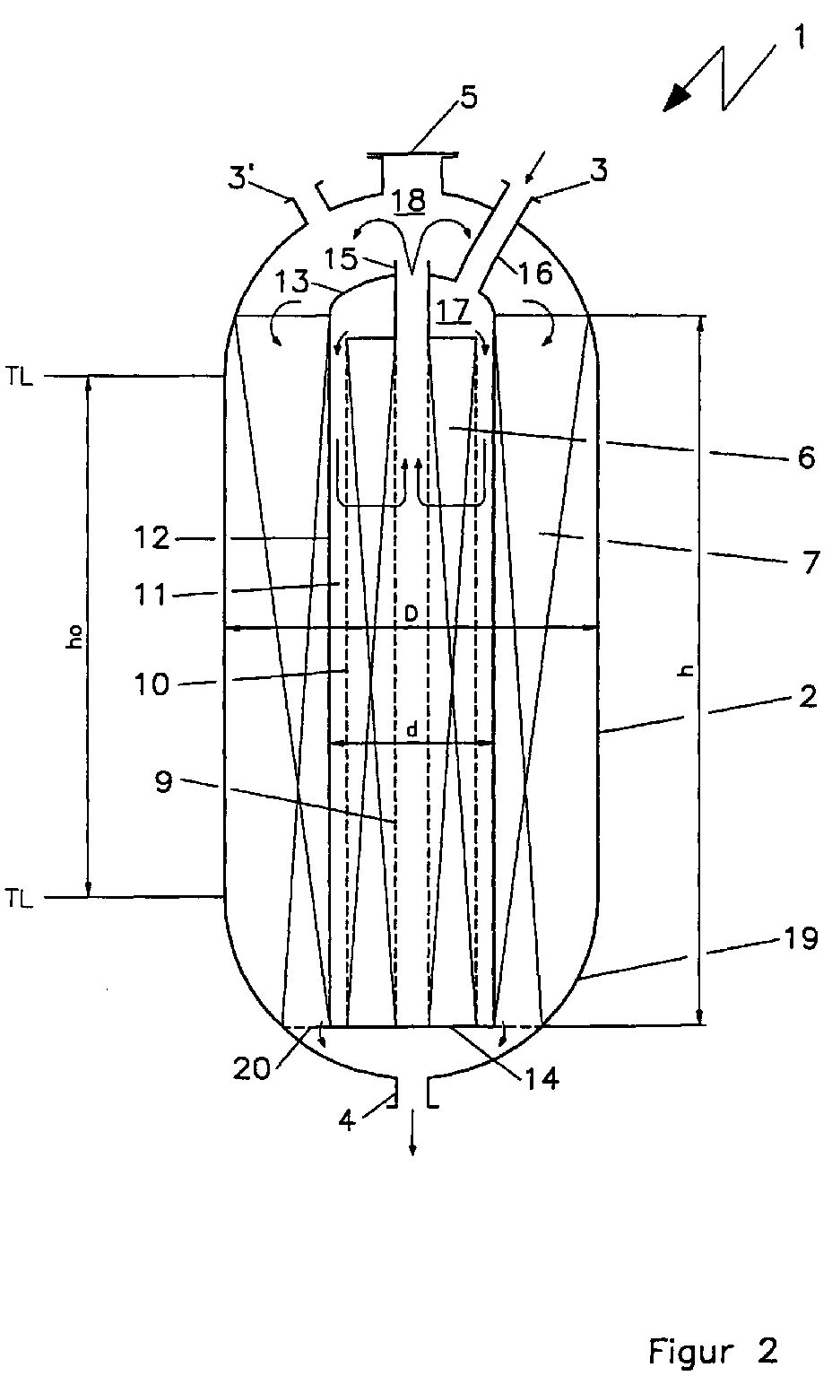
- the reactor 1 consists of a pressure vessel 2 with an inlet nozzle 3 and an outlet nozzle 4 for the fluid to be treated.
- a manhole 5 is centered, being inside the Housing 2 arranged a second cylindrical housing 12 which is centrally a perforated cylinder 9 or an outflow pipe 9 and therefore a perforated centrically further outside Contains tube 10, the space between the perforated Tubes 9 and 10 form the first catalyst bed 6.
- the outer wall 12 of this first catalyst vessel forms the inner wall for the second catalyst 7, in which illustrated example the first catalyst bed radially and arranged to flow axially through the second catalyst bed 7 is, without the invention being limited thereto.
- the dome 13 of the housing of the first catalyst bed 6 is penetrated by a perforated central tube 9 with a nozzle 15, the first catalyst housing 12 at the bottom End is completed with a bottom plate 14 which in the Support grid designated 20 for the second catalyst bed transforms.
- the mode of operation of the device according to the invention is based on the flow path of the fluid to be treated, the following:
- the gas to be treated is fed to the nozzle 3 and arrives via a line 16 in a first distributor or Dome space 17 and then into an inflow gap 11 in order then over the perforated wall 10 the first catalyst or to flow radially through the first catalyst bed 6, i.e. here from the outside in.
- the gas Via the perforated central tube 9 through the delivery port 15, the gas enters the second distributor or dome space 18 above the second catalyst bed 7 to penetrate from there, to flow axially and over the support ring 20 to Dispensing nozzle 4 to reach the bottom 19 of the reactor vessel 2 is arranged.
- a second feed pipe 3 ' is also immediate shown in the second distribution space 18.
- the gas be initiated such that it is only the second catalyst bed flows through, then around the first catalyst bed 6 easy to drive around.
- the possibility of the delivery nozzle is not shown 15 in the second cathedral space 18, if necessary, to the outside to continue using the first catalyst to be able to, for example, the second catalyst bed should be avoided.
Landscapes
- Chemical & Material Sciences (AREA)
- Organic Chemistry (AREA)
- Chemical Kinetics & Catalysis (AREA)
- Oil, Petroleum & Natural Gas (AREA)
- Physics & Mathematics (AREA)
- Fluid Mechanics (AREA)
- Engineering & Computer Science (AREA)
- General Chemical & Material Sciences (AREA)
- Devices And Processes Conducted In The Presence Of Fluids And Solid Particles (AREA)
- Organic Low-Molecular-Weight Compounds And Preparation Thereof (AREA)
- Catalysts (AREA)
- Physical Or Chemical Processes And Apparatus (AREA)
Abstract
Description
- Fig. 1
- einen entsprechenden Reaktor nach dem Stand der Technik und in
- Fig. 2
- eine Vorrichtung nach der Erfindung.
| Figur 1 | Figur 2 | |
| Volumen 6 [m3] | 13,6 | 13,6 |
| Volumen 7 [m3] | 66,5 | 66,5 |
| h0 [mm] | 11.000 | 5.500 |
| h [mm] | h0 | 7.500 |
| h1 [mm] | 7.800 | -- |
| h2 [mm] | 1.600 | -- |
| h3 [mm] | 1.600 | -- |
| D [mm] | 3.300 | 3.850 |
| d [mm] | -- | 1.700 |
| Gewicht kg | 109.000 | 80.000 |
Claims (4)
- Vorrichtung zur Durchführung katalytischer chemischer Reaktionen eines Fluids in der Gasphase, beispielsweise der Entschwefelung von Kohlenwasserstoffen, wie beispielsweise Erdgas, unter Einsatz zweier im Strömungsweg des Gases befindlicher Katalysatoren gleicher oder unterschiedlicher Art innerhalb eines gemeinsamen Gehäuses in zwei Katalysatorbetten, wobei ein im Gehäuse mittig angeordnetes Katalysatorbett von dem zweiten Katalysatorbett umgeben ist, dadurch gekennzeichnet,a) daß das im Strömungsweg erste Katalysatorbett (6) ein kleineres Katalysatorvolumen aufweist als das zweite Katalysatorbett (7),b) das erste und zweite Katalysatorbett (6,7) im wesentlichen zylindrisch ausgebildet sind, wobei die zylindrische Begrenzungswand (12) des inneren Katalysatorbettes (6) die zylindrische Innenwand des zweiten Katalysatorbettes (7) bildet undc) das erste Katalysatorbett (6) radial und das zweite Katalysatorbett (7) axial durchströmbar ist.
- Vorrichtung nach Anspruch 1,
dadurch gekennzeichnet,
daß die Abmessungen der Aufnahmen für das kleinere erste Katalysatorbett (6) und das größere zweite Katalysatorbett (7) so abgestimmt sind, daß die Füllhöhen beider Katalysatorbetten im Gesamtgehäuse (2) des Katalysators im wesentlichen gleich sind. - Vorrichtung nach Anspruch 1 oder 2,
dadurch gekennzeichnet,
daß auch das zweite Katalysatorbett (7) axial durchströmbar gestaltet ist. - Vorrichtung nach einem der vorangehenden Ansprüche,
dadurch gekennzeichnet,
daß im Dom des Gesamtkatalysatorgehäuses (2) neben dem Zufuhrstutzen (3) zum Dom (13) des inneren ersten Katalysatorbettes (6) ein zweiter Zufuhrstutzen (3') zur Umfahrung des ersten Katalysatorbettes (6) vorgesehen ist.
Applications Claiming Priority (2)
| Application Number | Priority Date | Filing Date | Title |
|---|---|---|---|
| DE19828777 | 1998-06-27 | ||
| DE19828777A DE19828777A1 (de) | 1998-06-27 | 1998-06-27 | Vorrichtung zur Durchführung katalytischer chemischer Reaktionen eines Fluids in der Gasphase |
Publications (3)
| Publication Number | Publication Date |
|---|---|
| EP0967006A2 true EP0967006A2 (de) | 1999-12-29 |
| EP0967006A3 EP0967006A3 (de) | 2000-05-24 |
| EP0967006B1 EP0967006B1 (de) | 2003-07-30 |
Family
ID=7872262
Family Applications (1)
| Application Number | Title | Priority Date | Filing Date |
|---|---|---|---|
| EP99111405A Expired - Lifetime EP0967006B1 (de) | 1998-06-27 | 1999-06-11 | Vorrichtung zur Durchführung katalytischer Reaktionen eines Fluids in der Gasphase |
Country Status (7)
| Country | Link |
|---|---|
| EP (1) | EP0967006B1 (de) |
| JP (1) | JP2000033258A (de) |
| AT (1) | ATE246038T1 (de) |
| CA (1) | CA2276221A1 (de) |
| DE (2) | DE19828777A1 (de) |
| DK (1) | DK0967006T3 (de) |
| ES (1) | ES2201596T3 (de) |
Cited By (3)
| Publication number | Priority date | Publication date | Assignee | Title |
|---|---|---|---|---|
| EP1338333A1 (de) * | 2002-02-14 | 2003-08-27 | Basf Aktiengesellschaft | Reaktorkaskade aus Haupt- und Nachreaktor |
| WO2003105998A1 (de) * | 2002-06-13 | 2003-12-24 | Uhde Gmbh | VERFAHREN UND VORRICHTUNG ZUR VERRINGERUNG DES GEHALTS AN NOx UND N2O IN GASEN |
| DE102011121188A1 (de) | 2011-12-16 | 2013-06-20 | Thyssen Krupp Uhde Gmbh | Vorrichtung und Verfahren zur Beseitigung von NOx und N20 |
Family Cites Families (10)
| Publication number | Priority date | Publication date | Assignee | Title |
|---|---|---|---|---|
| US1959219A (en) * | 1932-09-08 | 1934-05-15 | Forrest C Reed | Process of producing compounds containing carbon, hydrogen, and oxygen |
| US3544264A (en) * | 1968-09-25 | 1970-12-01 | Universal Oil Prod Co | Method and means for two-stage catalytic treating of engine exhaust gases |
| US3620685A (en) * | 1969-07-30 | 1971-11-16 | Phillips Petroleum Co | Radial flow catalyst reactor |
| US3902856A (en) * | 1971-10-05 | 1975-09-02 | Texaco Inc | Hydrogenation reactor with improved flow distribution |
| US3817716A (en) * | 1971-11-18 | 1974-06-18 | E Betz | Catalytic incineration apparatus |
| JPS61171530A (ja) * | 1985-01-23 | 1986-08-02 | Hitachi Ltd | 燃料改質器 |
| DK165946C (da) * | 1985-03-21 | 1993-07-05 | Haldor Topsoe As | Reformingproces under varmeudveksling og reaktor dertil |
| DE3607118A1 (de) * | 1986-03-05 | 1987-09-10 | Linde Ag | Verfahren und reaktor zur durchfuehrung einer katalytischen reaktion |
| DE3917325A1 (de) * | 1989-05-27 | 1990-11-29 | Metallgesellschaft Ag | Konverter fuer die katalytische umsetzung von gasfoermigen bestandteilen in gasen |
| DE19600549A1 (de) * | 1996-01-09 | 1997-07-10 | Linde Ag | Reaktor |
-
1998
- 1998-06-27 DE DE19828777A patent/DE19828777A1/de not_active Ceased
-
1999
- 1999-06-11 DE DE59906415T patent/DE59906415D1/de not_active Expired - Fee Related
- 1999-06-11 EP EP99111405A patent/EP0967006B1/de not_active Expired - Lifetime
- 1999-06-11 DK DK99111405T patent/DK0967006T3/da active
- 1999-06-11 AT AT99111405T patent/ATE246038T1/de not_active IP Right Cessation
- 1999-06-11 ES ES99111405T patent/ES2201596T3/es not_active Expired - Lifetime
- 1999-06-25 JP JP11180577A patent/JP2000033258A/ja not_active Withdrawn
- 1999-06-25 CA CA002276221A patent/CA2276221A1/en not_active Abandoned
Cited By (6)
| Publication number | Priority date | Publication date | Assignee | Title |
|---|---|---|---|---|
| EP1338333A1 (de) * | 2002-02-14 | 2003-08-27 | Basf Aktiengesellschaft | Reaktorkaskade aus Haupt- und Nachreaktor |
| WO2003105998A1 (de) * | 2002-06-13 | 2003-12-24 | Uhde Gmbh | VERFAHREN UND VORRICHTUNG ZUR VERRINGERUNG DES GEHALTS AN NOx UND N2O IN GASEN |
| US7462340B2 (en) | 2002-06-13 | 2008-12-09 | Unde Gmbh | Method and device for reducing the NOX and N2O of gases |
| DE102011121188A1 (de) | 2011-12-16 | 2013-06-20 | Thyssen Krupp Uhde Gmbh | Vorrichtung und Verfahren zur Beseitigung von NOx und N20 |
| WO2013087181A2 (de) | 2011-12-16 | 2013-06-20 | Thyssenkrupp Uhde Gmbh | Vorrichtung und verfahren zur beseitigung von nox und n2o |
| EP4631604A1 (de) | 2011-12-16 | 2025-10-15 | thyssenkrupp Uhde GmbH | Vorrichtung und verfahren zur beseitigung von nox und n2o |
Also Published As
| Publication number | Publication date |
|---|---|
| CA2276221A1 (en) | 1999-12-27 |
| EP0967006A3 (de) | 2000-05-24 |
| JP2000033258A (ja) | 2000-02-02 |
| EP0967006B1 (de) | 2003-07-30 |
| DE59906415D1 (de) | 2003-09-04 |
| DE19828777A1 (de) | 1999-12-30 |
| ATE246038T1 (de) | 2003-08-15 |
| ES2201596T3 (es) | 2004-03-16 |
| DK0967006T3 (da) | 2003-11-03 |
Similar Documents
| Publication | Publication Date | Title |
|---|---|---|
| DE3146778C2 (de) | ||
| DE2222562A1 (de) | Mehrstufiger Stapelreaktor fuer Katalysatorschichten mit bewegten Teilchen | |
| DE69732781T2 (de) | Verfahren zur in-situ Modernisierung eines heterogenen exothermen Synthesereaktors | |
| DE69530211T2 (de) | Vorrichtung zum strippen von wirbelschichtspaltungskatalysatoren | |
| DE2815856A1 (de) | Reaktor | |
| DE3130384A1 (de) | "vorrichtung fuer katalytische reaktionen" | |
| DE68908598T2 (de) | Apparat und Verfahren zum Wärmeaustausch zwischen Festpartikeln und einem Wärmeübertragungsmittel. | |
| DE2621953A1 (de) | Vorrichtung zum kontaktieren von fluiden mit feststoffen | |
| EP0967006B1 (de) | Vorrichtung zur Durchführung katalytischer Reaktionen eines Fluids in der Gasphase | |
| DE2751600A1 (de) | Vorrichtung zum reinigen der trommel eines rotations-waermetauschers | |
| EP0155341A2 (de) | Stehender Reaktor zur Erzeugung von Methanol | |
| DE3637871C1 (de) | Verfahren und Vorrichtung zur katalytischen Reduktion von Schadstoffen in Rauchgas | |
| WO2011144303A1 (de) | Abgasnachbehandlungsanlage | |
| DE69829549T2 (de) | Verfahren zur in-situ Modernisierung eines heterogenen Synthesereaktors | |
| DE19905733A1 (de) | Verfahren und Anlage zur Reinigung von mit Stickoxiden beladenen Abgasen | |
| EP0339251B1 (de) | Einrichtung zur Aufnahme von Katalysatoren, insbesondere bei der Erzeugung von Synthesegas | |
| DE3825724C2 (de) | Behälter | |
| DD269792A5 (de) | Katalytischer reaktor | |
| EP0166805B1 (de) | Wärmeübertragersystem | |
| EP0111615B1 (de) | Wärmeübertragersystem, vorzugsweise für ein Prozessgas | |
| EP1940542A1 (de) | Verteilervorrichtung für ein gas-flüssigphasengemisch für apparate | |
| WO2002099287A1 (de) | Pumpe zur förderung eines wärmetauschmittels für einen kontaktrohrbündelreaktor | |
| EP0807605B1 (de) | Gerät zum Entsalzen und Aufbereiten von Wasser | |
| AT395831B (de) | Verfahren und vorrichtung zur katalytischen reduktion von schadstoffen in rauchgas | |
| DE19904398B4 (de) | Lanze |
Legal Events
| Date | Code | Title | Description |
|---|---|---|---|
| PUAI | Public reference made under article 153(3) epc to a published international application that has entered the european phase |
Free format text: ORIGINAL CODE: 0009012 |
|
| AK | Designated contracting states |
Kind code of ref document: A2 Designated state(s): AT BE CH DE DK ES FR GB IT LI NL |
|
| AX | Request for extension of the european patent |
Free format text: AL;LT;LV;MK;RO;SI |
|
| PUAL | Search report despatched |
Free format text: ORIGINAL CODE: 0009013 |
|
| AK | Designated contracting states |
Kind code of ref document: A3 Designated state(s): AT BE CH CY DE DK ES FI FR GB GR IE IT LI LU MC NL PT SE |
|
| AX | Request for extension of the european patent |
Free format text: AL;LT;LV;MK;RO;SI |
|
| 17P | Request for examination filed |
Effective date: 20000609 |
|
| AKX | Designation fees paid |
Free format text: AT BE CH DE DK ES FR GB IT LI NL |
|
| RAP1 | Party data changed (applicant data changed or rights of an application transferred) |
Owner name: UHDE GMBH |
|
| GRAH | Despatch of communication of intention to grant a patent |
Free format text: ORIGINAL CODE: EPIDOS IGRA |
|
| GRAH | Despatch of communication of intention to grant a patent |
Free format text: ORIGINAL CODE: EPIDOS IGRA |
|
| GRAA | (expected) grant |
Free format text: ORIGINAL CODE: 0009210 |
|
| AK | Designated contracting states |
Designated state(s): AT BE CH DE DK ES FR GB IT LI NL |
|
| REG | Reference to a national code |
Ref country code: GB Ref legal event code: FG4D Free format text: NOT ENGLISH |
|
| REG | Reference to a national code |
Ref country code: CH Ref legal event code: NV Representative=s name: BOVARD AG PATENTANWAELTE Ref country code: CH Ref legal event code: EP |
|
| REF | Corresponds to: |
Ref document number: 59906415 Country of ref document: DE Date of ref document: 20030904 Kind code of ref document: P |
|
| REG | Reference to a national code |
Ref country code: DK Ref legal event code: T3 |
|
| GBT | Gb: translation of ep patent filed (gb section 77(6)(a)/1977) |
Effective date: 20031015 |
|
| REG | Reference to a national code |
Ref country code: ES Ref legal event code: FG2A Ref document number: 2201596 Country of ref document: ES Kind code of ref document: T3 |
|
| ET | Fr: translation filed | ||
| PLBE | No opposition filed within time limit |
Free format text: ORIGINAL CODE: 0009261 |
|
| STAA | Information on the status of an ep patent application or granted ep patent |
Free format text: STATUS: NO OPPOSITION FILED WITHIN TIME LIMIT |
|
| 26N | No opposition filed |
Effective date: 20040504 |
|
| PGFP | Annual fee paid to national office [announced via postgrant information from national office to epo] |
Ref country code: GB Payment date: 20050531 Year of fee payment: 7 |
|
| PGFP | Annual fee paid to national office [announced via postgrant information from national office to epo] |
Ref country code: FR Payment date: 20050610 Year of fee payment: 7 |
|
| PGFP | Annual fee paid to national office [announced via postgrant information from national office to epo] |
Ref country code: ES Payment date: 20050613 Year of fee payment: 7 Ref country code: DE Payment date: 20050613 Year of fee payment: 7 |
|
| PGFP | Annual fee paid to national office [announced via postgrant information from national office to epo] |
Ref country code: CH Payment date: 20050614 Year of fee payment: 7 |
|
| PGFP | Annual fee paid to national office [announced via postgrant information from national office to epo] |
Ref country code: NL Payment date: 20050615 Year of fee payment: 7 Ref country code: DK Payment date: 20050615 Year of fee payment: 7 Ref country code: AT Payment date: 20050615 Year of fee payment: 7 |
|
| PGFP | Annual fee paid to national office [announced via postgrant information from national office to epo] |
Ref country code: BE Payment date: 20050704 Year of fee payment: 7 |
|
| PG25 | Lapsed in a contracting state [announced via postgrant information from national office to epo] |
Ref country code: GB Free format text: LAPSE BECAUSE OF NON-PAYMENT OF DUE FEES Effective date: 20060611 Ref country code: AT Free format text: LAPSE BECAUSE OF NON-PAYMENT OF DUE FEES Effective date: 20060611 |
|
| PG25 | Lapsed in a contracting state [announced via postgrant information from national office to epo] |
Ref country code: ES Free format text: LAPSE BECAUSE OF NON-PAYMENT OF DUE FEES Effective date: 20060612 |
|
| PG25 | Lapsed in a contracting state [announced via postgrant information from national office to epo] |
Ref country code: LI Free format text: LAPSE BECAUSE OF NON-PAYMENT OF DUE FEES Effective date: 20060630 Ref country code: DK Free format text: LAPSE BECAUSE OF NON-PAYMENT OF DUE FEES Effective date: 20060630 Ref country code: CH Free format text: LAPSE BECAUSE OF NON-PAYMENT OF DUE FEES Effective date: 20060630 Ref country code: BE Free format text: LAPSE BECAUSE OF NON-PAYMENT OF DUE FEES Effective date: 20060630 |
|
| PG25 | Lapsed in a contracting state [announced via postgrant information from national office to epo] |
Ref country code: NL Free format text: LAPSE BECAUSE OF NON-PAYMENT OF DUE FEES Effective date: 20070101 |
|
| PG25 | Lapsed in a contracting state [announced via postgrant information from national office to epo] |
Ref country code: DE Free format text: LAPSE BECAUSE OF NON-PAYMENT OF DUE FEES Effective date: 20070103 |
|
| REG | Reference to a national code |
Ref country code: DK Ref legal event code: EBP |
|
| REG | Reference to a national code |
Ref country code: CH Ref legal event code: PL |
|
| GBPC | Gb: european patent ceased through non-payment of renewal fee |
Effective date: 20060611 |
|
| NLV4 | Nl: lapsed or anulled due to non-payment of the annual fee |
Effective date: 20070101 |
|
| REG | Reference to a national code |
Ref country code: FR Ref legal event code: ST Effective date: 20070228 |
|
| REG | Reference to a national code |
Ref country code: ES Ref legal event code: FD2A Effective date: 20060612 |
|
| BERE | Be: lapsed |
Owner name: *UHDE G.M.B.H. Effective date: 20060630 |
|
| PG25 | Lapsed in a contracting state [announced via postgrant information from national office to epo] |
Ref country code: FR Free format text: LAPSE BECAUSE OF NON-PAYMENT OF DUE FEES Effective date: 20060630 |
|
| PGFP | Annual fee paid to national office [announced via postgrant information from national office to epo] |
Ref country code: IT Payment date: 20100623 Year of fee payment: 12 |
|
| PG25 | Lapsed in a contracting state [announced via postgrant information from national office to epo] |
Ref country code: IT Free format text: LAPSE BECAUSE OF NON-PAYMENT OF DUE FEES Effective date: 20110611 |