EP0965802A2 - Chaudière à condensation - Google Patents
Chaudière à condensation Download PDFInfo
- Publication number
- EP0965802A2 EP0965802A2 EP99111195A EP99111195A EP0965802A2 EP 0965802 A2 EP0965802 A2 EP 0965802A2 EP 99111195 A EP99111195 A EP 99111195A EP 99111195 A EP99111195 A EP 99111195A EP 0965802 A2 EP0965802 A2 EP 0965802A2
- Authority
- EP
- European Patent Office
- Prior art keywords
- housing
- water
- zone
- interior
- boiler according
- Prior art date
- Legal status (The legal status is an assumption and is not a legal conclusion. Google has not performed a legal analysis and makes no representation as to the accuracy of the status listed.)
- Withdrawn
Links
Images

Classifications
-
- F—MECHANICAL ENGINEERING; LIGHTING; HEATING; WEAPONS; BLASTING
- F24—HEATING; RANGES; VENTILATING
- F24H—FLUID HEATERS, e.g. WATER OR AIR HEATERS, HAVING HEAT-GENERATING MEANS, e.g. HEAT PUMPS, IN GENERAL
- F24H1/00—Water heaters, e.g. boilers, continuous-flow heaters or water-storage heaters
- F24H1/22—Water heaters other than continuous-flow or water-storage heaters, e.g. water heaters for central heating
- F24H1/38—Water heaters other than continuous-flow or water-storage heaters, e.g. water heaters for central heating with water contained in separate elements, e.g. radiator-type element
-
- F—MECHANICAL ENGINEERING; LIGHTING; HEATING; WEAPONS; BLASTING
- F24—HEATING; RANGES; VENTILATING
- F24H—FLUID HEATERS, e.g. WATER OR AIR HEATERS, HAVING HEAT-GENERATING MEANS, e.g. HEAT PUMPS, IN GENERAL
- F24H1/00—Water heaters, e.g. boilers, continuous-flow heaters or water-storage heaters
- F24H1/22—Water heaters other than continuous-flow or water-storage heaters, e.g. water heaters for central heating
- F24H1/24—Water heaters other than continuous-flow or water-storage heaters, e.g. water heaters for central heating with water mantle surrounding the combustion chamber or chambers
- F24H1/26—Water heaters other than continuous-flow or water-storage heaters, e.g. water heaters for central heating with water mantle surrounding the combustion chamber or chambers the water mantle forming an integral body
-
- F—MECHANICAL ENGINEERING; LIGHTING; HEATING; WEAPONS; BLASTING
- F24—HEATING; RANGES; VENTILATING
- F24H—FLUID HEATERS, e.g. WATER OR AIR HEATERS, HAVING HEAT-GENERATING MEANS, e.g. HEAT PUMPS, IN GENERAL
- F24H1/00—Water heaters, e.g. boilers, continuous-flow heaters or water-storage heaters
- F24H1/22—Water heaters other than continuous-flow or water-storage heaters, e.g. water heaters for central heating
- F24H1/44—Water heaters other than continuous-flow or water-storage heaters, e.g. water heaters for central heating with combinations of two or more of the types covered by groups F24H1/24 - F24H1/40
-
- F—MECHANICAL ENGINEERING; LIGHTING; HEATING; WEAPONS; BLASTING
- F24—HEATING; RANGES; VENTILATING
- F24H—FLUID HEATERS, e.g. WATER OR AIR HEATERS, HAVING HEAT-GENERATING MEANS, e.g. HEAT PUMPS, IN GENERAL
- F24H8/00—Fluid heaters characterised by means for extracting latent heat from flue gases by means of condensation
-
- Y—GENERAL TAGGING OF NEW TECHNOLOGICAL DEVELOPMENTS; GENERAL TAGGING OF CROSS-SECTIONAL TECHNOLOGIES SPANNING OVER SEVERAL SECTIONS OF THE IPC; TECHNICAL SUBJECTS COVERED BY FORMER USPC CROSS-REFERENCE ART COLLECTIONS [XRACs] AND DIGESTS
- Y02—TECHNOLOGIES OR APPLICATIONS FOR MITIGATION OR ADAPTATION AGAINST CLIMATE CHANGE
- Y02B—CLIMATE CHANGE MITIGATION TECHNOLOGIES RELATED TO BUILDINGS, e.g. HOUSING, HOUSE APPLIANCES OR RELATED END-USER APPLICATIONS
- Y02B30/00—Energy efficient heating, ventilation or air conditioning [HVAC]
Definitions
- the invention relates to a condensing boiler for burning liquid or gaseous fuels from a water-bearing housing with flow and return connections and with a combustion chamber behind which several parallel to each other, to one of the heating gases flowable block summarized, essentially Water pockets through which heat transfer fluid can flow vertically are arranged.
- Such boilers are, for example, according to DE-U-91 06 654.9 known. Under the layout and arrangement of the water pockets for the so-called condensing operation of such boilers is to be understood that these water pockets due to their heat transfer area size specifically for condensation of the heating gases flowing through, the Arrangement of the pockets on the gas side is made so that the condensate formed can drain off.
- the pocket block is arranged in the return area of the boiler housing and must be designed to be large sufficient cooling of the heating gases until condensation to be able to achieve. With the boiler upwards DE-U-91 06 654 mentioned therefore takes the pocket block almost half of the entire boiler.
- the invention is based on a boiler type mentioned at the outset, based on the task of simple and cost-effective design and improve that the pockets of the pocket block in their function more specifically for a condensing boiler are parked so in relation to the overall size less than half of the boiler and thus the entire boiler is comparatively compact is to be trained.
- inflow hood and overflow hood Elements are ultimately baffles, which simply attach to the pocket block at the top and bottom are.
- baffles simply attach to the pocket block at the top and bottom are.
- the housing is preferably designed in such a way that the area of the housing containing the water pockets formed as a separately manufactured housing part and under hydraulic connection to the housing by welding or flange or piping is connected.
- the bags can be styled with a style , embossed vertical division are provided for others, it is also possible for each zone accordingly wide individual pockets arranged one behind the other to provide.
- the hot gas outlet side zone with a larger width dimensioned as the combustion chamber side zone.
- a vertically oriented, at least one-layer pipe register upstream is, whose pipes go down from the overflow channel and Open out in the interior of the housing area in which the pocket block is arranged.
- this Pipe register targeted from the overflow channel still relatively cold return to.
- the still preferably improved from two pipe layers with each other staggered pipes is formed, then the here already relatively strongly heated return directly in the water-bearing interior surrounding the combustion chamber the actual boiler housing.
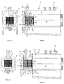
- the boiler still consists of a water-bearing one Housing 1 with flow and return connections 2,3 and with a combustion chamber 4, behind which several in parallel side by side arranged, to one through which the heating gases can flow
- Block 5 summarized, essentially vertical Water pockets 6 through which heat transfer medium can be arranged are.
- Zones 7,8 arranged directly next to each other are, from which the heating gas discharge side zone 8, delimited against the water-bearing interior I of the housing 1, upstream with the return port 3 in direter Connection is established and downstream, also delimited against the interior I, with the inflow side of the combustion chamber side Zone 7, the outflow side into the interior I of the housing 1 opens out.
- Fig. 5,6 the pocket block 5 are indeed superior and shielding tube register 13 also shown, in this regard but it should be noted that this is a special, but not mandatory embodiment acts, i.e. the pocket block can be in accordance with Fig. 1,3 also connect directly to the combustion chamber 4.
- the water pockets 6 are each in two vertically oriented flow zones 7,8 for the heat transfer medium structured. This results in a flow guidance as mentioned in the introduction, i.e. in the flow zone 8 this flows directly through the inflow hood 9 fed cold return water down that then, after deflection in the overflow hood 10, through the Flow zone 7 of the water pockets 6 and (if present) through a pipe register 13 up into the outflow space 21 and thus enters the housing 1.
- the water pockets are 6 in Form of a box-shaped unit or a box-shaped Bankgas gutströmkanales 22 to the bottom 23 of the Combustion chamber 4 of the housing 1 attached, the corresponding one Cutout for the heating gas flow channel of the pocket block 5 has.
- the special design of the water pockets 6 does not require any further explanation per se, since such water pockets and pocket blocks formed therefrom, through which heating gases can flow transversely, are well known in boiler construction, so also a training in that the wave-shaped, flanked pocket flanks are mutually related with respect to their waves support each other, which is also preferably provided in the present case.
- the vertical division VT for zone formation on the water exchanges 6 is preferably designed in such a way that the zone 7 on the exhaust gas outlet side is wider than the other zone 8. This is not particularly shown, since it is readily conceivable.
- combustion chambers 4 and pocket block 5 in the water-conducting interior I of the housing 1, i.e. a special hydraulic connection the arrangement areas of combustion chamber 4 and pocket block 5 is not required here.
- the pocket block sits in the exemplary embodiments according to FIG 5 in a separate and in this respect also advantageous separately manufactured, water-carrying housing part 1 ', between the end walls of the pocket block 5 according to Fig.7 is used.
- the end walls are with appropriate Provide cutouts, on the one hand upstream for the entry of the heating gases into block 5 and on the downstream side for the passage of the exhaust gas collection chamber 26, the part of the pocket block 5 and the flow channel for the heating gases.
- the tubes 14 of the in the embodiment of Fig. 5,6 with provided and upstream of the pocket block 5 preferably two-layer pipe register 13 also from of the overflow hood 10, which top in the interior I ' of the housing part 1 'open, so in the overflow hood 10 a flow restrictor (not particularly shown) to be arranged, since it ensures that the zone 8 inflowing return not to a large extent through the Pipe register 13 flows.
- the pipe register 13 can also be arranged so that, as shown in Fig.5, the lower area of the interior I 'directly with the upper Area or outflow space of the interior I 'through the Pipe register 13 is connected.
- the entire secondary heat exchanger can be used or the housing part 1 'inclusive of the tube register 13 advantageously as a completely separate unit manufacture that when assembled with the housing 1 naturally requires a gas-side seal.
- an embodiment is provided in that the otherwise essentially the cross section of the housing part 1 'corresponding cross section of the housing 1 upwards extended and to this extension 15 the upper manifold 12 connected.
Landscapes
- Engineering & Computer Science (AREA)
- Physics & Mathematics (AREA)
- Thermal Sciences (AREA)
- Chemical & Material Sciences (AREA)
- Combustion & Propulsion (AREA)
- Mechanical Engineering (AREA)
- General Engineering & Computer Science (AREA)
- Heat-Exchange Devices With Radiators And Conduit Assemblies (AREA)
- Combustion Of Fluid Fuel (AREA)
- Instantaneous Water Boilers, Portable Hot-Water Supply Apparatuses, And Control Of Portable Hot-Water Supply Apparatuses (AREA)
Priority Applications (1)
| Application Number | Priority Date | Filing Date | Title |
|---|---|---|---|
| DE29924567U DE29924567U1 (de) | 1998-06-12 | 1999-06-09 | Brennwertheizkessel |
Applications Claiming Priority (2)
| Application Number | Priority Date | Filing Date | Title |
|---|---|---|---|
| DE19826094A DE19826094A1 (de) | 1998-06-12 | 1998-06-12 | Heizkessel |
| DE19826094 | 1998-06-12 |
Publications (2)
| Publication Number | Publication Date |
|---|---|
| EP0965802A2 true EP0965802A2 (fr) | 1999-12-22 |
| EP0965802A3 EP0965802A3 (fr) | 2002-07-03 |
Family
ID=7870624
Family Applications (1)
| Application Number | Title | Priority Date | Filing Date |
|---|---|---|---|
| EP99111195A Withdrawn EP0965802A3 (fr) | 1998-06-12 | 1999-06-09 | Chaudière à condensation |
Country Status (2)
| Country | Link |
|---|---|
| EP (1) | EP0965802A3 (fr) |
| DE (1) | DE19826094A1 (fr) |
Cited By (2)
| Publication number | Priority date | Publication date | Assignee | Title |
|---|---|---|---|---|
| EP1698839A3 (fr) * | 2005-02-12 | 2006-11-02 | August Brötje GmbH | Chaudière |
| EP1813884A3 (fr) * | 2003-05-08 | 2007-10-24 | Alley Enterprises Limited | Unité de condensation |
Citations (1)
| Publication number | Priority date | Publication date | Assignee | Title |
|---|---|---|---|---|
| DE9106654U1 (de) | 1991-05-31 | 1991-07-25 | Vießmann, Hans, Dr.h.c., 3559 Battenberg | Heizkessel |
Family Cites Families (4)
| Publication number | Priority date | Publication date | Assignee | Title |
|---|---|---|---|---|
| DE8601896U1 (de) * | 1986-01-25 | 1986-04-03 | Vießmann, Hans, Dr.h.c., 3559 Battenberg | Kondensatheizkessel |
| DE9318680U1 (de) * | 1993-12-07 | 1994-02-24 | Vießmann, Hans, Dr., 35088 Battenberg | Gasheizkessel |
| EP0731322A3 (fr) * | 1995-03-10 | 1997-04-16 | Viessmann Werke Kg | Chaudière à haut rendement |
| DE29800377U1 (de) * | 1997-01-13 | 1998-04-16 | Vaillant Joh Gmbh & Co | Gas-Brennwertkessel |
-
1998
- 1998-06-12 DE DE19826094A patent/DE19826094A1/de not_active Withdrawn
-
1999
- 1999-06-09 EP EP99111195A patent/EP0965802A3/fr not_active Withdrawn
Patent Citations (1)
| Publication number | Priority date | Publication date | Assignee | Title |
|---|---|---|---|---|
| DE9106654U1 (de) | 1991-05-31 | 1991-07-25 | Vießmann, Hans, Dr.h.c., 3559 Battenberg | Heizkessel |
Cited By (2)
| Publication number | Priority date | Publication date | Assignee | Title |
|---|---|---|---|---|
| EP1813884A3 (fr) * | 2003-05-08 | 2007-10-24 | Alley Enterprises Limited | Unité de condensation |
| EP1698839A3 (fr) * | 2005-02-12 | 2006-11-02 | August Brötje GmbH | Chaudière |
Also Published As
| Publication number | Publication date |
|---|---|
| DE19826094A1 (de) | 1999-12-23 |
| EP0965802A3 (fr) | 2002-07-03 |
Similar Documents
| Publication | Publication Date | Title |
|---|---|---|
| DE2706043C2 (de) | Strahlungsbrenner | |
| DE1551450B2 (de) | Wirbelschicht Verbrennungsofen | |
| DE112007003550B4 (de) | Kessel mit flachen horizontalen Röhren | |
| DE3318722A1 (de) | Waermetauscher | |
| EP0965802A2 (fr) | Chaudière à condensation | |
| DE2734031C2 (de) | Mobiler Naßdampf-Zwangsdurchlaufdampferzeuger | |
| DE102008039403A1 (de) | Heizgerät | |
| DE10236665B4 (de) | Gas-Flüssigkeits-Wärmetauscher und damit ausgerüsteter Boiler | |
| DE29924567U1 (de) | Brennwertheizkessel | |
| DE69805841T2 (de) | Flüssigkeitserhitzer | |
| DE2911020C2 (de) | Stahlheizungskessel | |
| DE2917759C2 (fr) | ||
| DE10026550C1 (de) | Heizkessel für die Verbrennung flüssiger oder gasförmiger Brennstoffe | |
| EP1288586B1 (fr) | Chaudière sectionnable en fonte | |
| EP0566945B1 (fr) | Installation pour réchauffer de l'eau, en particulier chaudière à eau | |
| DE202011110101U1 (de) | Wärmetauscheranordung | |
| DE102008026074B3 (de) | Wärmetauscher | |
| EP1953474B1 (fr) | Chaudière à carburant solide | |
| EP0816776A2 (fr) | Chauffe-eau à gaz et chambre de combustion refroidie par eau | |
| DE19548084A1 (de) | Heizkessel | |
| CH693966A5 (de) | Heizkoerper und Anschlussgarnitur. | |
| AT408146B (de) | Heizeinrichtung | |
| DE1779329C3 (de) | Kombinierter gasbeheizter Wasser- und Lufterhitzer | |
| DE4107948C1 (en) | Heating gas flue pocket of two sheet metal blanks - top, conically tapering inlet duct, and conically widening, lower outlet duct | |
| DE3519727A1 (de) | Brennwertkessel mit integriertem kondensationswaermetauscher |
Legal Events
| Date | Code | Title | Description |
|---|---|---|---|
| PUAI | Public reference made under article 153(3) epc to a published international application that has entered the european phase |
Free format text: ORIGINAL CODE: 0009012 |
|
| AK | Designated contracting states |
Kind code of ref document: A2 Designated state(s): AT BE CH CY DE DK ES FI FR GB GR IE IT LI LU MC NL PT SE |
|
| AX | Request for extension of the european patent |
Free format text: AL;LT;LV;MK;RO;SI |
|
| PUAL | Search report despatched |
Free format text: ORIGINAL CODE: 0009013 |
|
| AK | Designated contracting states |
Kind code of ref document: A3 Designated state(s): AT BE CH CY DE DK ES FI FR GB GR IE IT LI LU MC NL PT SE |
|
| AX | Request for extension of the european patent |
Free format text: AL;LT;LV;MK;RO;SI |
|
| RIC1 | Information provided on ipc code assigned before grant |
Free format text: 7F 24H 8/00 A, 7F 24H 1/44 B, 7F 24H 1/28 B |
|
| 17P | Request for examination filed |
Effective date: 20020715 |
|
| AKX | Designation fees paid |
Designated state(s): AT BE CH DE FR GB IT LI NL |
|
| GRAP | Despatch of communication of intention to grant a patent |
Free format text: ORIGINAL CODE: EPIDOSNIGR1 |
|
| STAA | Information on the status of an ep patent application or granted ep patent |
Free format text: STATUS: THE APPLICATION IS DEEMED TO BE WITHDRAWN |
|
| 18D | Application deemed to be withdrawn |
Effective date: 20031201 |