EP0965732A1 - Anneau de sertissage avec prise de vapeur pour turbine - Google Patents
Anneau de sertissage avec prise de vapeur pour turbine Download PDFInfo
- Publication number
- EP0965732A1 EP0965732A1 EP98810543A EP98810543A EP0965732A1 EP 0965732 A1 EP0965732 A1 EP 0965732A1 EP 98810543 A EP98810543 A EP 98810543A EP 98810543 A EP98810543 A EP 98810543A EP 0965732 A1 EP0965732 A1 EP 0965732A1
- Authority
- EP
- European Patent Office
- Prior art keywords
- inner housing
- shrink ring
- ring
- steam turbine
- turbine
- Prior art date
- Legal status (The legal status is an assumption and is not a legal conclusion. Google has not performed a legal analysis and makes no representation as to the accuracy of the status listed.)
- Granted
Links
Images


Classifications
-
- F—MECHANICAL ENGINEERING; LIGHTING; HEATING; WEAPONS; BLASTING
- F01—MACHINES OR ENGINES IN GENERAL; ENGINE PLANTS IN GENERAL; STEAM ENGINES
- F01D—NON-POSITIVE DISPLACEMENT MACHINES OR ENGINES, e.g. STEAM TURBINES
- F01D25/00—Component parts, details, or accessories, not provided for in, or of interest apart from, other groups
- F01D25/24—Casings; Casing parts, e.g. diaphragms, casing fastenings
- F01D25/26—Double casings; Measures against temperature strain in casings
Definitions
- the invention relates to a high-pressure or medium-pressure turbine as a single machine or a combined high-pressure medium-pressure turbine with a lower and upper part existing inner housing and an outer housing, and in particular one Connection of these parts of the inner housing by means of shrink rings and a Tapping to discharge steam from the turbine into a pipeline to one apparatus standing outside the turbine.
- a tap slot is arranged on the outer contour of the blade duct of the turbine, which leads through the inner housing into the space between the inner and outer housing.
- the steam flows from the turbine blade vane through the bleed slot and is collected in a sealed annulus formed over the bleed slot by a molded bleed ring in the form of a tire on the outer surface of the inner casing. This is sealingly attached to the inner housing.
- a pipe socket is arranged on the ring, which leads through the outer housing to the outside and to which a pipe is connected which leads to a feed water preheater, boiler or other heating apparatus.
- the shrink rings and the tapping ring are each fixed to the inner housing by several bolts and screws, so that the rings cannot move with respect to the housing.
- a disadvantage of this prior art is that the tapping and the holding together of the inner housing by means of shrink rings in the area of the tapping and several components and small parts are required, which are manufactured and assembled individually.
- the production of a cast tapping ring requires several manufacturing steps. For the many components and small parts required, there is ultimately a long manufacturing and assembly time and the resulting high costs.
- a steam turbine according to the preamble of claim 1, which has a shrink ring in the region of the tapping, which is arranged above the tapping slot of the turbine and, at the location of the tapping slot, has a semi-open cavity facing the inner housing, the cavity together with the outer surface of the inner housing forms an annular space in which the bleed steam flowing through the bleed slot collects.
- the shrink ring is flat on both sides of the cavity so that its contours match those of the inner housing.
- the shrink ring thus combines the function of both the shrink ring and the tap ring in a single part and is referred to here as a combined shrink ring tap ring.
- the shrink ring has an opening for a removal nozzle, which leads sealingly through the outer housing to a pipeline.
- the advantage of the combined shrink ring according to the invention is that it consists of a single component, which has both functions, that of holding the turbine housing parts together and that of forming a collecting space for bleed steam from the turbine. Instead of several parts as in the prior art described at the outset, only one part has to be manufactured and assembled for these two functions.
- the combined shrink ring tap ring according to the invention is rotated in one operation by means of a forging sleeve. Because only a large part has to be produced instead of several parts, the production time is significantly reduced. In particular, castings that require several costly work steps are no longer necessary. The assembly time is also reduced because only one part has to be assembled instead of several parts. Finally, the number of small parts, such as axial fixings, is considerably reduced, which saves further time during assembly.
- FIG. 1 shows a steam turbine 1 with a tapping ring and shrink ring according to the prior art. It has a shaft 2 and a blade duct 3, with moving blades 4 and guide blades 5.
- the steam turbine 1 is enclosed by an inner casing 6 and an outer casing 7.
- On the outer contour of the blade duct 3, the steam turbine has a tap slot 8 which leads through 360 ° through the inner housing 6 into the space between the inner and outer housing 6, 7.
- the inner housing 6 is held together along the tapping slot 8 by a plurality of ribs 9 distributed around the circumference, one of which is indicated in the figure with a broken line.
- a cast tapping ring 11 in the form of a tire is arranged on the outer surface of the inner housing 6 at the height of the tapping slot 8, a closed, tight annular space 10 being formed above the tapping slot 8 by the tapping ring 11 and the inner housing 6.
- the tapping ring 11 is fixed to the inner housing 6 by retaining rings 12.
- the inner housing 6 is also held together by a plurality of shrink rings 14.
- FIG. 2 shows a steam turbine 1 of a type similar to that described in FIG. 1 but with the combined shrink ring tapping ring according to the invention.
- the combined shrink ring tapping ring 20 consists of a single forged part. On the sides 21, the inside of the shrink ring 20 is flat and adapted to the outer surface of the inner housing 6, so that the ring 20 seals against the inner housing during the shrinking. In the middle, the combined shrink ring tapping ring 20 has a semi-open cavity on the side facing the inner housing 6.
- the ring 20 is pushed over the inner housing 6 of the turbine and arranged in such a way that the cavity comes to lie over the tapping slot 8.
- the cavity with the outer surface of the inner housing 6 forms a free annular space 10 above the tap slot 8.
- the steam flows through the tap slot 8 and collects and distributes in the annular space 10.
- the cavity has a round cross section in the embodiment shown .
- Other cross sections, such as square cross sections, are also conceivable here. However, a round cross-section is more favorable considering the flow through the annulus to the pipeline leading out of the turbine.
- the outer contour has a curvature 23, which forms a type of bridge from one side part 21 of the combined shrink ring to the other side part 21.
- the curved shape makes the shrink ring more flexible, which is advantageous in the case of the thermal expansions of the inner housing 6.
- the straight outer contour of the combined shrink ring tapping ring 20 is also conceivable and would be simpler in terms of production technology.
- the curvature 23 is somewhat more complex to produce in comparison.
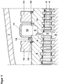
- FIG. 3 shows a further view of the combined shrink ring tapping ring 20.
- the bulge 23 the cavity on the inside and the flat parts 21 on the sides of the ring are shown in the middle of the ring 20.
- an opening 22 is arranged in the lower region, which is used to mount a tapping nozzle 24 for guiding the bleed steam through the outer housing.
- the opening 22 is designed such that the removal nozzle 24 can be arranged vertically. A vertical arrangement simplifies installation through the outer housing.
- the opening is preferably located in the lower region of the shrink ring tapping ring 20, so that any condensate can run out. However, an opening in the upper area is also conceivable.
- the extraction nozzle 24 is arranged in Figure 3 slightly offset from the lowest point on the ring.
- the extraction nozzle 24 is expediently designed such that the flow from the annular space 10 into the extraction nozzle 24 is favored as much as possible.
- both the diameter of the extraction nozzle is at least equal to the width of the cavity and the end of the extraction nozzle is adapted to the contours of the annular space so that no edges protrude into the annular space.
- the tapping nozzle is welded to the inner housing in a sealing manner. In an alternative embodiment, this connection is realized by screwing or jamming.
Landscapes
- Engineering & Computer Science (AREA)
- Mechanical Engineering (AREA)
- General Engineering & Computer Science (AREA)
- Turbine Rotor Nozzle Sealing (AREA)
Priority Applications (5)
| Application Number | Priority Date | Filing Date | Title |
|---|---|---|---|
| EP98810543A EP0965732B1 (fr) | 1998-06-15 | 1998-06-15 | Anneau de sertissage avec prise de vapeur pour turbine |
| DE59808462T DE59808462D1 (de) | 1998-06-15 | 1998-06-15 | Schrumpfring für Turbine mit Anzapfung |
| CNB991080297A CN1246571C (zh) | 1998-06-15 | 1999-06-08 | 用于抽汽式涡轮机的收缩环 |
| US09/328,433 US6203271B1 (en) | 1998-06-15 | 1999-06-09 | Shrink ring for turbine with bleeding |
| JP11165616A JP2000054806A (ja) | 1998-06-15 | 1999-06-11 | タ―ビンのための抽出手段を有する収縮リング |
Applications Claiming Priority (1)
| Application Number | Priority Date | Filing Date | Title |
|---|---|---|---|
| EP98810543A EP0965732B1 (fr) | 1998-06-15 | 1998-06-15 | Anneau de sertissage avec prise de vapeur pour turbine |
Publications (2)
| Publication Number | Publication Date |
|---|---|
| EP0965732A1 true EP0965732A1 (fr) | 1999-12-22 |
| EP0965732B1 EP0965732B1 (fr) | 2003-05-21 |
Family
ID=8236134
Family Applications (1)
| Application Number | Title | Priority Date | Filing Date |
|---|---|---|---|
| EP98810543A Expired - Lifetime EP0965732B1 (fr) | 1998-06-15 | 1998-06-15 | Anneau de sertissage avec prise de vapeur pour turbine |
Country Status (5)
| Country | Link |
|---|---|
| US (1) | US6203271B1 (fr) |
| EP (1) | EP0965732B1 (fr) |
| JP (1) | JP2000054806A (fr) |
| CN (1) | CN1246571C (fr) |
| DE (1) | DE59808462D1 (fr) |
Cited By (3)
| Publication number | Priority date | Publication date | Assignee | Title |
|---|---|---|---|---|
| EP1744017A1 (fr) * | 2005-07-14 | 2007-01-17 | Siemens Aktiengesellschaft | Turbine combinée à vapeur et procédé de fonctionnement d'une turbine combinée à vapeur |
| US7402024B2 (en) | 2005-02-16 | 2008-07-22 | Alstom Technology Ltd. | Steam turbine |
| EP2101042A1 (fr) * | 2008-03-10 | 2009-09-16 | Siemens Aktiengesellschaft | Turbine à vapeur dotée de frettes |
Families Citing this family (8)
| Publication number | Priority date | Publication date | Assignee | Title |
|---|---|---|---|---|
| US6337861B1 (en) * | 1999-02-02 | 2002-01-08 | Cisco Technology, Inc. | Method and apparatus to properly route ICMP messages in a tag-switching network |
| US7729267B2 (en) * | 2003-11-26 | 2010-06-01 | Cisco Technology, Inc. | Method and apparatus for analyzing a media path in a packet switched network |
| US7738383B2 (en) * | 2006-12-21 | 2010-06-15 | Cisco Technology, Inc. | Traceroute using address request messages |
| US7706278B2 (en) * | 2007-01-24 | 2010-04-27 | Cisco Technology, Inc. | Triggering flow analysis at intermediary devices |
| US20130078089A1 (en) * | 2011-09-26 | 2013-03-28 | General Electric Company | Steam turbine single shell extraction lp casing |
| CN103422916B (zh) * | 2013-08-30 | 2015-09-30 | 上海电气电站设备有限公司 | 汽轮机的抽、补汽通道结构 |
| CN105626168B (zh) * | 2016-02-26 | 2017-09-15 | 上海发电设备成套设计研究院 | 汽轮机红套环高压内缸的严密性监控方法及系统 |
| CN105756724B (zh) * | 2016-02-26 | 2017-09-22 | 上海发电设备成套设计研究院 | 汽轮机红套环与高压内缸红套紧力的监控方法及系统 |
Citations (2)
| Publication number | Priority date | Publication date | Assignee | Title |
|---|---|---|---|---|
| GB600025A (en) * | 1945-04-13 | 1948-03-30 | Power Jets Res & Dev Ltd | Improvements in and relating to casings for turbines, compressors and the like |
| FR2323904A1 (fr) * | 1975-09-11 | 1977-04-08 | Carrier Corp | Bague de compensation pour machine tournante |
-
1998
- 1998-06-15 DE DE59808462T patent/DE59808462D1/de not_active Expired - Fee Related
- 1998-06-15 EP EP98810543A patent/EP0965732B1/fr not_active Expired - Lifetime
-
1999
- 1999-06-08 CN CNB991080297A patent/CN1246571C/zh not_active Expired - Fee Related
- 1999-06-09 US US09/328,433 patent/US6203271B1/en not_active Expired - Fee Related
- 1999-06-11 JP JP11165616A patent/JP2000054806A/ja active Pending
Patent Citations (2)
| Publication number | Priority date | Publication date | Assignee | Title |
|---|---|---|---|---|
| GB600025A (en) * | 1945-04-13 | 1948-03-30 | Power Jets Res & Dev Ltd | Improvements in and relating to casings for turbines, compressors and the like |
| FR2323904A1 (fr) * | 1975-09-11 | 1977-04-08 | Carrier Corp | Bague de compensation pour machine tournante |
Cited By (4)
| Publication number | Priority date | Publication date | Assignee | Title |
|---|---|---|---|---|
| US7402024B2 (en) | 2005-02-16 | 2008-07-22 | Alstom Technology Ltd. | Steam turbine |
| EP1744017A1 (fr) * | 2005-07-14 | 2007-01-17 | Siemens Aktiengesellschaft | Turbine combinée à vapeur et procédé de fonctionnement d'une turbine combinée à vapeur |
| WO2007006754A1 (fr) | 2005-07-14 | 2007-01-18 | Siemens Aktiengesellschaft | Turbine a vapeur combinee, ensemble de turbines a vapeur ou de turbines a gaz et a vapeur et procede pour faire fonctionner une turbine a vapeur combinee |
| EP2101042A1 (fr) * | 2008-03-10 | 2009-09-16 | Siemens Aktiengesellschaft | Turbine à vapeur dotée de frettes |
Also Published As
| Publication number | Publication date |
|---|---|
| EP0965732B1 (fr) | 2003-05-21 |
| JP2000054806A (ja) | 2000-02-22 |
| US6203271B1 (en) | 2001-03-20 |
| CN1246571C (zh) | 2006-03-22 |
| DE59808462D1 (de) | 2003-06-26 |
| CN1239178A (zh) | 1999-12-22 |
Similar Documents
| Publication | Publication Date | Title |
|---|---|---|
| EP2123860B1 (fr) | Redresseur de tourbillons combiné | |
| EP0589215B1 (fr) | Turbine à gaz avec carter d'échappement et conduit d'échappement | |
| DE19821889B4 (de) | Verfahren und Vorrichtung zur Durchführung von Reparatur- und/oder Wartungsarbeiten im Innengehäuse einer mehrschaligen Turbomaschine | |
| EP1898054B1 (fr) | Turbine a gaz | |
| DE2258719A1 (de) | Gasturbine | |
| EP0903468A1 (fr) | Bandage annulaire pour turbine axiale | |
| EP3548705B1 (fr) | Turbochargeur | |
| DE10159670A1 (de) | Wirbelgleichrichter im Hochdruckverdichter einer Gasturbine | |
| EP0848150A2 (fr) | Dispositif de nettoyage pour la turbine d'une turbo-soufflante | |
| DE10325649A1 (de) | Abgasturbine für einen Abgasturbolader | |
| EP0965732B1 (fr) | Anneau de sertissage avec prise de vapeur pour turbine | |
| DE102009042857A1 (de) | Gasturbine mit Deckband-Labyrinthdichtung | |
| EP0397768B1 (fr) | Turbine pour turbocompresseur | |
| EP0491966B1 (fr) | Dispositif de support d'une turbomachine thermique | |
| EP0745756B1 (fr) | Dispositif et méthode de montage d'aubes de rotor | |
| EP0040267B1 (fr) | Stator refroidi pour turbines | |
| DE1966660A1 (de) | Gasturbine mit mehreren umkehrstrombrennkammern | |
| EP0806547B1 (fr) | Turbine axiale pour turbocompresseurs | |
| DE7502516U (de) | Thermische turbomaschine, insbesondere niederdruck-dampfturbine | |
| EP1744014A1 (fr) | Agencement de montage des aubes d'entrée d'une turbine à gaz | |
| EP1687512B1 (fr) | Turbocompresseur comprenant un dispositif de nettoyage | |
| DE2060509A1 (de) | Vorrichtung zum Abblasen von Verdichterluft | |
| EP3034784A1 (fr) | Possibilité de refroidissement pour turbomachines | |
| DE60113826T2 (de) | Turbolader mit Leitschaufelkranzankoppelung | |
| EP0961869B1 (fr) | Etancheification de brides dans la section d'admission d'une enveloppe de turbine |
Legal Events
| Date | Code | Title | Description |
|---|---|---|---|
| PUAI | Public reference made under article 153(3) epc to a published international application that has entered the european phase |
Free format text: ORIGINAL CODE: 0009012 |
|
| AK | Designated contracting states |
Kind code of ref document: A1 Designated state(s): DE FR GB IT |
|
| AX | Request for extension of the european patent |
Free format text: AL;LT;LV;MK;RO;SI |
|
| 17P | Request for examination filed |
Effective date: 20000510 |
|
| RAP1 | Party data changed (applicant data changed or rights of an application transferred) |
Owner name: ABB ALSTOM POWER (SCHWEIZ) AG |
|
| AKX | Designation fees paid |
Free format text: DE FR GB IT |
|
| RAP1 | Party data changed (applicant data changed or rights of an application transferred) |
Owner name: ALSTOM |
|
| GRAH | Despatch of communication of intention to grant a patent |
Free format text: ORIGINAL CODE: EPIDOS IGRA |
|
| RAP1 | Party data changed (applicant data changed or rights of an application transferred) |
Owner name: ALSTOM (SWITZERLAND) LTD |
|
| GRAH | Despatch of communication of intention to grant a patent |
Free format text: ORIGINAL CODE: EPIDOS IGRA |
|
| GRAA | (expected) grant |
Free format text: ORIGINAL CODE: 0009210 |
|
| AK | Designated contracting states |
Designated state(s): DE FR GB IT |
|
| PG25 | Lapsed in a contracting state [announced via postgrant information from national office to epo] |
Ref country code: GB Free format text: LAPSE BECAUSE OF FAILURE TO SUBMIT A TRANSLATION OF THE DESCRIPTION OR TO PAY THE FEE WITHIN THE PRESCRIBED TIME-LIMIT Effective date: 20030521 Ref country code: FR Free format text: LAPSE BECAUSE OF FAILURE TO SUBMIT A TRANSLATION OF THE DESCRIPTION OR TO PAY THE FEE WITHIN THE PRESCRIBED TIME-LIMIT Effective date: 20030521 |
|
| REG | Reference to a national code |
Ref country code: GB Ref legal event code: FG4D Free format text: NOT ENGLISH |
|
| REF | Corresponds to: |
Ref document number: 59808462 Country of ref document: DE Date of ref document: 20030626 Kind code of ref document: P |
|
| GBV | Gb: ep patent (uk) treated as always having been void in accordance with gb section 77(7)/1977 [no translation filed] |
Effective date: 20030521 |
|
| PLBE | No opposition filed within time limit |
Free format text: ORIGINAL CODE: 0009261 |
|
| STAA | Information on the status of an ep patent application or granted ep patent |
Free format text: STATUS: NO OPPOSITION FILED WITHIN TIME LIMIT |
|
| 26N | No opposition filed |
Effective date: 20040224 |
|
| EN | Fr: translation not filed | ||
| PGFP | Annual fee paid to national office [announced via postgrant information from national office to epo] |
Ref country code: DE Payment date: 20070622 Year of fee payment: 10 |
|
| PGFP | Annual fee paid to national office [announced via postgrant information from national office to epo] |
Ref country code: IT Payment date: 20070625 Year of fee payment: 10 |
|
| PG25 | Lapsed in a contracting state [announced via postgrant information from national office to epo] |
Ref country code: DE Free format text: LAPSE BECAUSE OF NON-PAYMENT OF DUE FEES Effective date: 20090101 |
|
| PG25 | Lapsed in a contracting state [announced via postgrant information from national office to epo] |
Ref country code: IT Free format text: LAPSE BECAUSE OF NON-PAYMENT OF DUE FEES Effective date: 20080615 |