EP0965724B1 - Antriebsvorrichtung einer in zwei Richtungen drehbaren rohrförmigen Walze, Rolladenwalze mit einer derartigen Antriebsvorrichtung, Rolladen mit einer derartigen Walze - Google Patents
Antriebsvorrichtung einer in zwei Richtungen drehbaren rohrförmigen Walze, Rolladenwalze mit einer derartigen Antriebsvorrichtung, Rolladen mit einer derartigen Walze Download PDFInfo
- Publication number
- EP0965724B1 EP0965724B1 EP99490016A EP99490016A EP0965724B1 EP 0965724 B1 EP0965724 B1 EP 0965724B1 EP 99490016 A EP99490016 A EP 99490016A EP 99490016 A EP99490016 A EP 99490016A EP 0965724 B1 EP0965724 B1 EP 0965724B1
- Authority
- EP
- European Patent Office
- Prior art keywords
- mobile element
- signal
- mobile
- drum
- ring
- Prior art date
- Legal status (The legal status is an assumption and is not a legal conclusion. Google has not performed a legal analysis and makes no representation as to the accuracy of the status listed.)
- Expired - Lifetime
Links
Images
Classifications
-
- E—FIXED CONSTRUCTIONS
- E06—DOORS, WINDOWS, SHUTTERS, OR ROLLER BLINDS IN GENERAL; LADDERS
- E06B—FIXED OR MOVABLE CLOSURES FOR OPENINGS IN BUILDINGS, VEHICLES, FENCES OR LIKE ENCLOSURES IN GENERAL, e.g. DOORS, WINDOWS, BLINDS, GATES
- E06B9/00—Screening or protective devices for wall or similar openings, with or without operating or securing mechanisms; Closures of similar construction
- E06B9/56—Operating, guiding or securing devices or arrangements for roll-type closures; Spring drums; Tape drums; Counterweighting arrangements therefor
- E06B9/68—Operating devices or mechanisms, e.g. with electric drive
- E06B9/72—Operating devices or mechanisms, e.g. with electric drive comprising an electric motor positioned inside the roller
-
- H—ELECTRICITY
- H02—GENERATION; CONVERSION OR DISTRIBUTION OF ELECTRIC POWER
- H02P—CONTROL OR REGULATION OF ELECTRIC MOTORS, ELECTRIC GENERATORS OR DYNAMO-ELECTRIC CONVERTERS; CONTROLLING TRANSFORMERS, REACTORS OR CHOKE COILS
- H02P23/00—Arrangements or methods for the control of AC motors characterised by a control method other than vector control
- H02P23/24—Controlling the direction, e.g. clockwise or counterclockwise
-
- H—ELECTRICITY
- H02—GENERATION; CONVERSION OR DISTRIBUTION OF ELECTRIC POWER
- H02P—CONTROL OR REGULATION OF ELECTRIC MOTORS, ELECTRIC GENERATORS OR DYNAMO-ELECTRIC CONVERTERS; CONTROLLING TRANSFORMERS, REACTORS OR CHOKE COILS
- H02P25/00—Arrangements or methods for the control of AC motors characterised by the kind of AC motor or by structural details
- H02P25/02—Arrangements or methods for the control of AC motors characterised by the kind of AC motor or by structural details characterised by the kind of motor
- H02P25/04—Single phase motors, e.g. capacitor motors
-
- E—FIXED CONSTRUCTIONS
- E06—DOORS, WINDOWS, SHUTTERS, OR ROLLER BLINDS IN GENERAL; LADDERS
- E06B—FIXED OR MOVABLE CLOSURES FOR OPENINGS IN BUILDINGS, VEHICLES, FENCES OR LIKE ENCLOSURES IN GENERAL, e.g. DOORS, WINDOWS, BLINDS, GATES
- E06B9/00—Screening or protective devices for wall or similar openings, with or without operating or securing mechanisms; Closures of similar construction
- E06B9/56—Operating, guiding or securing devices or arrangements for roll-type closures; Spring drums; Tape drums; Counterweighting arrangements therefor
- E06B9/68—Operating devices or mechanisms, e.g. with electric drive
- E06B2009/6809—Control
- E06B2009/6872—Control using counters to determine shutter position
Definitions
- the present invention relates to a drive device a tubular member movable in bi-directional rotation, a drum roller shutter equipped with such a drive device and a roller shutter equipped of such a drum.
- the invention may also be used in all areas of economic activity in which we want drive a tubular member movable in bi-directional rotation.
- a first drawback of such solutions is that they require the use of a large number of mechanical parts in contact with each other, susceptible to wear and causing problems sealing.
- this device does not constitute ends as such because it does not detect the direction of variation of the movable member.
- the object of the present invention is to provide a device for driving a tubular member, in particular a roller shutter drum, mobile in bi-directional rotation which allows to overcome aforementioned drawbacks and the risks of wear of which are reduced.
- Another object of the present invention is to provide a device for driving a tubular member, in particular a flap drum rolling, movable in bi-directional rotation, in which the number of mechanical parts may be limited.
- Another object of the present invention is to provide a device for driving a tubular member, in particular a flap drum rolling, bi-directional mobile, which can be waterproof.
- the present invention relates to a device for driving a tubular member, in particular roller shutter drum, movable in bi-directional rotation around its longitudinal axis, as defined in claim 1.
- the present invention further relates to a shutter drum roller, provided with such a drive device, and a roller shutter provided with such drum.
- the present invention relates to a drive device a tubular member, in particular roller shutter drum, movable in rotation bidirectionally.
- said device comprises, according to the invention, a system for controlling the position of said movable member 2, provided with first means 4 for creating a periodic physical signal, in particular a periodic magnetic flux, and second means 5 for detect without contact the variations of said signal and to identify the direction of description of the period, one of said first or second means 4, 5 being provided driven, directly or indirectly, by said movable member 2, and the other of said first or second means 4, 5 being provided fixed opposite.
- a remote detection system ensures the sealing of the interior of the support means, which is essential since they contain the electrical and electronic components motor and control means integrated into said sub-assembly.
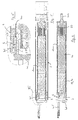
- Said support means consist for example of a tube of circular section accommodating one beside the other said means of control 19, 30, a motor 10 and a reduction gear 22 whose movable axis 104 is provided opening to cooperate with said movable member 2 via of a transmission transmission part 105.
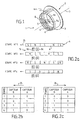
- Said means 4 for creating a signal are constituted, in particular, by a succession of magnet poles 6. These are, possibly evenly distributed.
- said means 4 for creating a signal consist of a bi-polar magnet and / or north and south poles of magnets alternating punctually with each other on a support surface.
- said magnet poles 6 are provided contiguous.
- Said magnets 6 are thus, for example, provided distributed circularly around an axis intended to define the axis of rotation 7 of the movable member 2.
- the succession of north and south poles of magnets 6 is made up, for example, in a known manner, of magnetic rubber, of a strip magnetic, permanent magnets and / or materials that have undergone induction magnetization. It can still be, possibly, materials magnetized molded, overmolded or obtained by sintering according to the shape desired.
- Said succession of north and south poles of magnets 6 is mounted on its support, for example, by gluing, riveting, screwing, overmolding, clipping, embedding or other.
- the means 5 for non-contact detection of signal variations and to identify the direction of description of the period are planned moving while the succession of magnet poles 6 is provided fixed opposite.
- Said means 5 for detecting the signal without contact and for identify the meaning of description of the period consist, for example, of minus two magnetic flux sensors 9a, 9b.
- inductive type Hall effect sensors with reed bulb or others. They may, if necessary, be protected in resin.
- Said sensors 9a, 9b could also, if necessary, be located axially, in particular when said means for creating the signal 4 are located on one and / or the other side of a disc-shaped support, for example centered on said axis of rotation 7.
- sensors 9a, 9b are provided oriented radially and arranged internally.
- said sensors 9a, 9b can then be associated with processing means provided internally in the movable member 2 tubular.
- Said sensors 9a, 9b are, for example, provided spaced apart so as to be able to identify two successions of different signals depending the direction of movement of the movable member 2 and therefore the direction of description of the period of the variations of the magnetic flux.
- FIGs 2b and 2c illustrate as binary information the signals read by the sensors 9a, 9b according to the four stages shown in Figure 2a.
- Table 2b corresponds to a given direction, marked 25, of displacement of the signal creation means 4 while table 2c corresponds to the opposite direction, marked 26.
- monitoring periodic reversals of the flow magnetic can be extended, according to the same principle, beyond the four steps shown in Figures 2a to 2c.
- information noted by the sensors 9a, 9b is for example, translated into electrical impulses, including variations in voltage and / or current, with successive states corresponding to zero or one, depending on the pole present in front of the sensor considered.
- Said means 4 for creating the periodic signal are provided, for example at a ring 3, consisting at least in part of a material capable of undergoing magnetization by induction to define a succession north and / or south poles of magnets, distributed in a ring, along the axis longitudinal of said ring 3.
- Said ring 3 is provided in particular rotating relative to to said support means 100, and provided with means 101 for cooperating with said movable member 2, such as in particular a key, so that its movements are the image of the movements of said movable member 2.
- Said means 5 for detecting variations in the signal and for spot the direction of description of its period are provided, for example, at inside said support means.
- Said means 4 for creating the signal and said means 5 for detect variations in the signal and to identify the direction of description of its period are, in particular, provided at one end of said support means 100, called the first end.
- Said first end is, in particular, provided with a plug 102 for said support means 100.
- a seal 103 is provided between said plug and said support means 100.
- control means further comprise optionally, processing means 30, capable at least of giving a digitized image of the position of said movable member 2 as a function of information recorded by said means 5 to detect variations in the signal and identify the direction of description of its period.
- the absence magnetization can also be assimilated to specific information.
- control means In order to be able to detect arrivals at the end of the race the movable member 2, said control means optionally have, means for comparing the position of said member with positions of limit switches recorded.
- the processing means 30 are provided capable of operate in two different modes, one says "normal” and the other says “Setting”.
- the first authorizes, for example, the monitoring and blocking of the organ mobile when it reaches the saved limit positions while the second authorizes, in particular, the adjustment and / or modification of them.
- electrical means 31 for mode selection the processing means 30 are provided, said means electric 31 being further able to authorize the selection of end positions for their memorization, when the movable member has arrived at the desired position.
- a digitized signal for tracking the positions of the mobile organ, digital processing means and means of electrical selection thus allows, for example, the realization of electrical wiring, allowing remote adjustment of end positions race and facilitating operator interventions.
- Said processing means 30 are provided capable of producing, for example, counting functions from the signal giving the image of the position of the organ. They are provided for this, in particular, with one or more counters.
- Said processing means 30 also allow, by example, comparing the value of the counter (s) with a value corresponding to the end-of-travel positions, these being provided for stored, in particular, in a memory.
- Said processing means 30 also allow, by example, storing the limit values set in said memory and / or the issuance of a blocking order from the movable member in the event of correspondence between the values appearing in the counter (s) and those stored in memory.
- Said processing means 30 are further provided suitable, for example, to authorize a switching of their operation between the “normal” mode and “setting” mode, in particular using data input established from electric current also allowing the setting movement of the mobile organ.
- said processing means 30 carry out so, for example, counting functions, comparison of values counted with the limit values, and issuance of blocking order in match, while in "setting” mode, the comparison of the values counted with the limit values is possibly inhibited and replaced by the news storage function limit values set.
- said processing means 30 take into account counts, for example, the signal or signals giving the image of the position of the mobile organ and / or the signal or signals determining their mode of operation. On exit, they issue, for example, blocking orders of said movable member.
- Said processing means 30 comprise, for example, a microprocessor, capable of implementing software allowing the realization, in particular, of said counting functions, comparison, storage, switching and / or blocking order transmission.
- Said counters consist, for example, of a counter position of the movable member, a limit switch and / or a time counter.
- said selection means 31 are possibly provided capable of adjusting the end of travel positions on the fly, that is to say during the actual movement of the movable member.
- the stored values then correspond, for example, to the counter value after stopping said movable member at the position that you want to save as an end position.
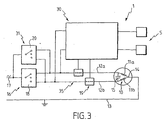
- said drive device comprises, by example, motor means 10 for driving the movable member and / or means 16 for selecting the operating mode of said motor means 10.
- Said means 16 for selecting the operating mode said motor means 10 allow an operator to choose, for example, the direction of movement of said movable member and / or keeping it stationary.
- said processing means 30 are connected by mounting in bypass on a supply line 35 provided between said motor means 10 and said means 16 for selecting the operating mode of said motor means 10.
- Said supply line 35 consists for example of two cables 12a, 12b each allowing the supply of said motor means 10 for operation in a given direction.
- Said means 16 for selecting the operating mode said motor means 10 are, for example, connected to the network, marked 17, and are optionally provided capable of isolating said supply line 35 from this one. This prevents the control device from being permanently powered. In addition, such an arrangement allows, if desired, to control multiple motors from a single control point.
- the means 31 for selecting the operating mode of the means processing 30 and the end position consist of means for simultaneous tensioning of cables 12a, 12b. Said power up is planned temporary. It ceases, for example, when the movable member is arrived at the desired position to define an end position.
- Said motor means consist, in particular, of a motor having, for example, two windings 11a, 11b allowing each rotation in a given direction.
- Said windings 11a, 11b are provided, in particular, between one of the cables 12a, 12b, forming a phase line and a neutral line 13, possibly connected to a common point 14 provided between the said windings 11a, 11b.
- a capacity 15 is, for example, provided at the level of said windings 11a, 11b between their terminals opposite the common point 14.
- Said control means further comprise, by example, blocking means 19 of said motor means 10. They are consisting, in particular, of a circuit breaker member provided on each of the cables 12a, 12b.
- Said means 16 for selecting the operating mode said motor means 10 and / or said means 31 for selecting the mode of operation of the processing means 30 and of the end-of-travel positions consist, for example, of a three-position switch. It is located, in particular, between sector 17 and said supply line 35.
- Said switch could be constituted, for example, for said means 16 for selecting the operating mode of the means motor 10, a blind 18, and for said means 31 of the selection mode processing means 30, a microswitch 20.
- one of the terminals corresponds to a direction of movement of the movable member, the second to the other direction of movement of this and the third at the stop of the engine means.
- a first of the terminals corresponds to the mode for setting a first end position, a second to the setting mode of the second end position and the third terminal in normal operating mode.
- the operator activates the blind 18 to connect the phase line 12a with the sector and allow the displacement of the movable member in the direction concerned. Simultaneously, the other phase line 12b is cut at using the circuit breaker 19 provided thereon.
- the processing means 30 being connected in bypass to said phase lines 12a, 12b, they then note the appearance at the input of a state different from the normal state, each of said lines 12a, 12b being supplied, instead of just one, upstream of the locking means 19.
- the mode limit switch is activated.
- Said drive device further comprises, possibly to promote the functioning of said processing means 30, a stabilized supply between them and said supply line 35.
- Said conversion means comprise, among others, a voltage divider, a rectifier and / or a filter.
- the present invention also relates to a shutter drum rolling, equipped with the drive device described above.
- the motor 10 drives through of the reducer 22 the drum 2 intended to allow the winding / unwinding of the roller shutter deck which is also the subject of the invention.
- Said drum 2, said ring 3 and said piece 105 of transmission are mobile in rotation.
- Said means of cooperation between said ring 3 and said drum 2 consist, in particular, of a groove 107 and a key 108 provided on these items.
Landscapes
- Engineering & Computer Science (AREA)
- Power Engineering (AREA)
- Structural Engineering (AREA)
- Architecture (AREA)
- Civil Engineering (AREA)
- Operating, Guiding And Securing Of Roll- Type Closing Members (AREA)
Claims (12)
- Vorschubeinrichtung eines röhrenförmigen Organs (2), insbesondere einer Trommel für Rolladen, die in Drehung in beide Richtungen um ihre Längsachse beweglich ist, umfassend Motormittel (10, 22) für die Drehung des besagten beweglichen Organs (2), Mittel zum Steuern (19, 30) der besagten Motormittel in Abhängigkeit von Informationen, die wenigstens durch das besagte System zur Kontrolle der Position des beweglichen Organs geliefert werden, und ein System zur Kontrolle der Position des besagten beweglichen Organs (2), wobei das besagte System erste Mittel (4), um ein periodisches physisches Signal zu schaffen, und zweite Mittel (5), um die Veränderungen des besagten Signals kontaktlos festzustellen, umfaßt, wobei vorgesehen ist, daß eines von den besagten ersten oder zweiten Mitteln (4, 5) durch das besagte bewegliche Organ (2) direkt oder indirekt angetrieben wird, und das andere von den besagten ersten oder zweiten Mitteln (4, 5) unbeweglich gegenüberliegend vorgesehen ist,
dadurch gekennzeichnet, daß die besagte Vorschubeinrichtung durch ein Trägermittel (100) gebildet ist, vorgesehen, in das besagte bewegliche Organ (2) eingeführt zu werden, um seine Drehung zu erlauben, wobei das besagte röhrenförmig vorgesehene Trägermittel (100) innerlich die besagten Motormittel (10, 22), die besagten Steuermittel (19, 30) und das eine (5) von den besagten ersten oder zweiten Mitteln des besagten Systems zur Kontrolle der Position des beweglichen Organs aufnimmt,
daß das andere (4) von den besagten ersten oder zweiten Mitteln gegenüberliegend beweglich in Drehung um das besagte röhrenförmige Trägermittel (100) gelagert ist, derart, um mit dem besagten beweglichen Organ (2) zusammenwirken zu können, und
daß die ersten und die zweiten Mittel (4, 5) geeignet sind, die Beschreibungsrichtung der Periode zu bezeichnen. - Vorrichtung nach Anspruch 1, dadurch gekennzeichnet, daß die besagten ersten Mittel (4) beweglich in Drehung um das besagte röhrenförmige Trägermittel (100) gelagert sind und durch eine Reihenfolge von Magnetpolen (6) gebildet sind, die kreisförmig um eine Achse verteilt sind, die vorgesehen ist, die Drehachse (7) des beweglichen Organs (2) zu bilden, wobei die besagten zweiten Mittel (5), um das Signal kontaktlos festzustellen und um die Beschreibungsrichtung der Periode zu bezeichnen, durch wenigstens zwei Magnetflußsensoren (9a, 9b) gebildet sind, die beabstandet sind, derart, um zwei Reihenfolgen unterschiedlicher Signale in Abhängigkeit von der Verschiebungsrichtung des beweglichen Organs (2) bezeichnen zu können, wobei die besagten ersten Mittel (4), um das Signal zu schaffen, im Bereich eines Rings (3) vorgesehen sind, der durch eine Reihenfolge von magnetischen Nordund/oder Südpolen gebildet ist, die nach der Art einer Krone nach der Längsachse des Rings verteilt sind, wobei der besagte Ring (3) rotierend hinsichtlich des besagten röhrenförmigen Mittels (100) vorgesehen ist, und die besagten Sensoren (9a, 9b) sich innerlich des besagten Rings (3) befindend vorgesehen sind.
- Vorrichtung nach Anspruch 2, bei der die besagten Magneten (6) regelmäßig verteilt und/oder dicht anliegend vorgesehen sind.
- Vorrichtung nach Anspruch 1, bei der die besagten Sensoren (9a, 9b) an den besagten Mitteln (4) zur Schaffung des Signals radial angeordnet, innerlich und/oder äußerlich, und/oder axial vorgesehen sind.
- Vorrichtung nach Anspruch 2, bei der die besagten Mittel (4), um das Signal zu schaffen, im Bereich des Rings (3) vorgesehen sind, der wenigstens zum Teil aus einem Material gebildet ist, das geeignet ist, einer Magnetisierung durch Induktion unterzogen zu werden, um eine Reihenfolge von magnetischen Nord- und/oder Südpolen zu bilden, die nach der Art einer Krone nach der Längsachse des besagten Rings (3) verteilt sind.
- Vorrichtung nach Anspruch 2, bei welcher der besagte Ring (3) mit Mitteln (101) ausgestattet ist, um mit dem besagten beweglichen Organ (2) zusammenzuwirken, derart, daß seine Bewegungen das Bild der Bewegungen des besagten beweglichen Organs (2) sind.
- Vorrichtung nach Anspruch 6, bei der die besagten Mittel (5), um die Veränderungen des Signals festzustellen und um die Beschreibungsrichtung seiner Periode zu bezeichnen, im Inneren des besagten Trägermittels vorgesehen sind.
- Vorrichtung nach Ansprüchen 1 oder 7, bei der die besagten Mittel (4), um das Signal zu schaffen, und die besagten Mittel (5), um die Veränderungen des Signals festzustellen und um die Beschreibungsrichtung seiner Periode zu bezeichnen, an einem der Enden des besagten Trägermittels (100) vorgesehen sind, das als erstes Ende bezeichnet wird.
- Vorrichtung nach Anspruch 8, bei der das besagte erste Ende mit einem Stöpsel (102) für das besagte Trägermittel (100) ausgestattet ist.
- Vorrichtung nach Anspruch 9, bei der ein Dichtring (103) zwischen dem besagten Stöpsel und dem besagten Trägermittel (100) vorgesehen ist.
- Trommel für Rolladen, die mit einer Vorschubeinrichtung nach Anspruch 1 ausgestattet ist.
- Rolladen, der mit der Trommel nach Anspruch 11 ausgestattet ist.
Applications Claiming Priority (2)
| Application Number | Priority Date | Filing Date | Title |
|---|---|---|---|
| FR9807944A FR2780090B1 (fr) | 1998-06-19 | 1998-06-19 | Dispositif d'entrainement d'un organe, notamment tambour de volet roulant, et dispositif de protection d'une ouverture, notamment volet roulant, equipe d'un dispositif d'entrainement |
| FR9807944 | 1998-06-19 |
Publications (2)
| Publication Number | Publication Date |
|---|---|
| EP0965724A1 EP0965724A1 (de) | 1999-12-22 |
| EP0965724B1 true EP0965724B1 (de) | 2004-10-06 |
Family
ID=9527760
Family Applications (1)
| Application Number | Title | Priority Date | Filing Date |
|---|---|---|---|
| EP99490016A Expired - Lifetime EP0965724B1 (de) | 1998-06-19 | 1999-06-18 | Antriebsvorrichtung einer in zwei Richtungen drehbaren rohrförmigen Walze, Rolladenwalze mit einer derartigen Antriebsvorrichtung, Rolladen mit einer derartigen Walze |
Country Status (3)
| Country | Link |
|---|---|
| EP (1) | EP0965724B1 (de) |
| DE (1) | DE69920807T2 (de) |
| FR (1) | FR2780090B1 (de) |
Families Citing this family (8)
| Publication number | Priority date | Publication date | Assignee | Title |
|---|---|---|---|---|
| FR2821885B1 (fr) * | 2001-03-12 | 2007-04-13 | Bubendorff Volet Roulant | Dispositif de fixation de la tete d'un moteur tubulaire de volet roulant |
| FR2862334B1 (fr) | 2003-11-19 | 2006-02-10 | Somfy | Dispositif d'entrainement d'un ecran de fermeture ou de protection solaire et installation comportant un tel dispositif |
| FR2869349B1 (fr) * | 2004-04-26 | 2008-01-04 | Jouvence Sarl | Procede de commande du mouvement d'un tablier de volet roulant et dispositif pour la mise en oeuvre du procede |
| WO2006008218A1 (en) * | 2004-07-23 | 2006-01-26 | Jolly Motor International S.P.A. | Detector of angular position for driving devices with incorporated tubular gear motor for roller shutters |
| EP1752606B1 (de) * | 2005-08-09 | 2007-11-14 | Alcatel Lucent | Antriebseinheit für Gegenstände, die auf ein Rohr auf- und abgewickelt werden |
| ES2275426B2 (es) * | 2005-10-07 | 2009-02-01 | Joan Ventayol I Pinyol | Dispositivo de control de la posicion de una cortina, persiana o toldo y los medios de accionamiento de dicho dispositivo. |
| DE202007016283U1 (de) * | 2007-11-13 | 2009-03-26 | Arca Beteiligungen Gmbh | Antriebsanordnung für eine Verdunkelungsvorrichtung |
| DE202010003095U1 (de) * | 2010-03-02 | 2011-11-16 | Arca Beteiligungen Gmbh | Rohrmotoranordnung für eine Verdunkelungsvorrichtung |
Family Cites Families (8)
| Publication number | Priority date | Publication date | Assignee | Title |
|---|---|---|---|---|
| DE3346242A1 (de) * | 1983-12-21 | 1985-07-04 | Kurt Schlattingen Kunz | Verfahren zum ansteuern eines rollo-antriebsmotors sowie steuerung zur ausfuehrung des verfahrens |
| FR2673234A1 (fr) * | 1991-02-26 | 1992-08-28 | Kraemer Thierry | Dispositif de surveillance du fonctionnement de portes automatiques. |
| DE4201971A1 (de) * | 1992-01-22 | 1993-08-05 | Wilhelm Rademacher | Verdunkelungsvorrichtung |
| DE4311267A1 (de) * | 1993-04-06 | 1994-10-20 | Tornado Antriebstech Gmbh | Positionsgeber |
| DE4414280A1 (de) * | 1994-04-23 | 1995-10-26 | Bosch Gmbh Robert | Vorrichtung zur Erfassung der Drehbewegung eines Zahn- oder Nockenrads |
| DE4440449C2 (de) * | 1994-11-14 | 1997-06-12 | Elero Antrieb Sonnenschutz | Verfahren und Vorrichtung zur Stillstandssteuerung von elektromotorisch betriebenen Rolläden oder dergleichen |
| ATE257212T1 (de) * | 1995-10-28 | 2004-01-15 | Elero Gmbh | Verfahren zum antreiben von elektromotorisch betriebenen markisen oder dergleichen |
| DE19630491C1 (de) * | 1996-07-29 | 1998-02-05 | Selve Ernst Gmbh Co Kg | Schaltungsanordnung zur Steuerung von elektromotorischen Antrieben für auf- und abwickelbare Behänge |
-
1998
- 1998-06-19 FR FR9807944A patent/FR2780090B1/fr not_active Expired - Fee Related
-
1999
- 1999-06-18 EP EP99490016A patent/EP0965724B1/de not_active Expired - Lifetime
- 1999-06-18 DE DE69920807T patent/DE69920807T2/de not_active Expired - Lifetime
Also Published As
| Publication number | Publication date |
|---|---|
| DE69920807D1 (de) | 2004-11-11 |
| FR2780090A1 (fr) | 1999-12-24 |
| FR2780090B1 (fr) | 2000-08-11 |
| EP0965724A1 (de) | 1999-12-22 |
| DE69920807T2 (de) | 2005-10-13 |
Similar Documents
| Publication | Publication Date | Title |
|---|---|---|
| EP0162780B1 (de) | Einrichtung zum Feststellen der Rotordrehstelle einer drehenden Maschine | |
| EP0965724B1 (de) | Antriebsvorrichtung einer in zwei Richtungen drehbaren rohrförmigen Walze, Rolladenwalze mit einer derartigen Antriebsvorrichtung, Rolladen mit einer derartigen Walze | |
| FR2947902A1 (fr) | Capteur de position absolue et multi-periodique | |
| FR2891962A1 (fr) | Dispositif pour la determination de l'inversion effective du sens de rotation d'un entrainement rotatif reversible. | |
| FR2470477A1 (fr) | Moteur a courant continu sans balai | |
| FR2798787A1 (fr) | Procede et circuit de detection de la position du rotor d'un moteur a reluctance commutee et systeme de traitement utilise a cet effet | |
| FR3032475A1 (de) | ||
| EP3171231B1 (de) | Stossdetektorschaltkreis und sein funktionsverfahren | |
| FR2820252A1 (fr) | Systeme de controle de moteurs sans balais | |
| FR2844591A1 (fr) | Dispositif de determination du deplacement d'un arbre | |
| EP2966414A1 (de) | Montage eines systems zur bestimmung der winkelposition auf einem drehorgan | |
| EP0189732B1 (de) | Antriebsvorrichtung für einen elektrischen Motor mit dauermagnetisiertem Rotor | |
| FR2703450A1 (fr) | Codeur numérique incrémental absolu, installation et machine comportant ce codeur. | |
| EP1404016B1 (de) | Vorrichtung zur Steuerung eines elektronischen kommutierten Motor mit winkelverteilten Singularitäten | |
| WO2004084402A1 (fr) | Dispositif de commutation, palier a roulement et moteur electrique utilisant un tel dispositif | |
| EP0194911B1 (de) | Winkelpositionsmessvorrichtung mit Coderad | |
| EP1909150B1 (de) | Uhr, die Mittel zur Bestimmung der Drehstellung eines analogen Anzeigeelementes der Uhr aufweist | |
| FR3028942A1 (fr) | Capteur inductif de mesure de la position d'un arbre d'un vehicule | |
| EP4042113A1 (de) | Verfahren zur erkennung einer absoluten winkelposition oder eines absoluten winkelbewegungspfades eines rotierenden elements | |
| FR2861112A1 (fr) | Commande automatique ou manuelle des moteurs d'entrainement en deplacement de translation du dernier module d'un abri de piscine sans guidage au sol | |
| EP0965725A1 (de) | Einrichtung zur Endstellungsanzeige eines bidirektionalen mobilen Elements, nämlich einer Rolladenwickelwelle, und Antriebsvorrichtung eines bidirektionalen mobilen Elements ausgerüstet mit solcher Endstellungseinrichtung | |
| EP3172832B1 (de) | Verfahren und einheit zum steuern und/oder schützen eines aktuators eines teils einer mobilen ausrüstung eines gebäudes | |
| FR2593290A1 (fr) | Detecteur de vitesse et de sens de rotation pour machine tournante | |
| EP2997334B1 (de) | Positionskodierer | |
| FR2920181A1 (fr) | Procede de fonctionnement d'un actionneur electromecanique pour la manoeuvre motorisee d'un ecran et actionneur pour sa mise en oeuvre |
Legal Events
| Date | Code | Title | Description |
|---|---|---|---|
| PUAI | Public reference made under article 153(3) epc to a published international application that has entered the european phase |
Free format text: ORIGINAL CODE: 0009012 |
|
| AK | Designated contracting states |
Kind code of ref document: A1 Designated state(s): BE CH DE ES FR GB IT LI |
|
| AX | Request for extension of the european patent |
Free format text: AL;LT;LV;MK;RO;SI |
|
| 17P | Request for examination filed |
Effective date: 20000515 |
|
| AKX | Designation fees paid |
Free format text: BE CH DE ES FR GB IT LI |
|
| 17Q | First examination report despatched |
Effective date: 20030708 |
|
| GRAP | Despatch of communication of intention to grant a patent |
Free format text: ORIGINAL CODE: EPIDOSNIGR1 |
|
| GRAS | Grant fee paid |
Free format text: ORIGINAL CODE: EPIDOSNIGR3 |
|
| GRAA | (expected) grant |
Free format text: ORIGINAL CODE: 0009210 |
|
| AK | Designated contracting states |
Kind code of ref document: B1 Designated state(s): BE CH DE ES FR GB IT LI |
|
| PG25 | Lapsed in a contracting state [announced via postgrant information from national office to epo] |
Ref country code: IT Free format text: LAPSE BECAUSE OF FAILURE TO SUBMIT A TRANSLATION OF THE DESCRIPTION OR TO PAY THE FEE WITHIN THE PRESCRIBED TIME-LIMIT;WARNING: LAPSES OF ITALIAN PATENTS WITH EFFECTIVE DATE BEFORE 2007 MAY HAVE OCCURRED AT ANY TIME BEFORE 2007. THE CORRECT EFFECTIVE DATE MAY BE DIFFERENT FROM THE ONE RECORDED. Effective date: 20041006 Ref country code: GB Free format text: LAPSE BECAUSE OF FAILURE TO SUBMIT A TRANSLATION OF THE DESCRIPTION OR TO PAY THE FEE WITHIN THE PRESCRIBED TIME-LIMIT Effective date: 20041006 Ref country code: ES Free format text: LAPSE BECAUSE OF FAILURE TO SUBMIT A TRANSLATION OF THE DESCRIPTION OR TO PAY THE FEE WITHIN THE PRESCRIBED TIME-LIMIT Effective date: 20041006 |
|
| REG | Reference to a national code |
Ref country code: GB Ref legal event code: FG4D Free format text: NOT ENGLISH |
|
| REG | Reference to a national code |
Ref country code: CH Ref legal event code: EP |
|
| REF | Corresponds to: |
Ref document number: 69920807 Country of ref document: DE Date of ref document: 20041111 Kind code of ref document: P |
|
| RAP2 | Party data changed (patent owner data changed or rights of a patent transferred) |
Owner name: J.D.H. |
|
| RAP2 | Party data changed (patent owner data changed or rights of a patent transferred) |
Owner name: DEPRAT JEAN SA |
|
| GBV | Gb: ep patent (uk) treated as always having been void in accordance with gb section 77(7)/1977 [no translation filed] |
Effective date: 20041006 |
|
| PG25 | Lapsed in a contracting state [announced via postgrant information from national office to epo] |
Ref country code: LI Free format text: LAPSE BECAUSE OF NON-PAYMENT OF DUE FEES Effective date: 20050630 Ref country code: CH Free format text: LAPSE BECAUSE OF NON-PAYMENT OF DUE FEES Effective date: 20050630 Ref country code: BE Free format text: LAPSE BECAUSE OF NON-PAYMENT OF DUE FEES Effective date: 20050630 |
|
| PLBE | No opposition filed within time limit |
Free format text: ORIGINAL CODE: 0009261 |
|
| STAA | Information on the status of an ep patent application or granted ep patent |
Free format text: STATUS: NO OPPOSITION FILED WITHIN TIME LIMIT |
|
| 26N | No opposition filed |
Effective date: 20050707 |
|
| REG | Reference to a national code |
Ref country code: CH Ref legal event code: PL |
|
| REG | Reference to a national code |
Ref country code: FR Ref legal event code: CL |
|
| BERE | Be: lapsed |
Owner name: S.A. *DEPRAT JEAN Effective date: 20050630 |
|
| REG | Reference to a national code |
Ref country code: FR Ref legal event code: PLFP Year of fee payment: 18 |
|
| PGFP | Annual fee paid to national office [announced via postgrant information from national office to epo] |
Ref country code: DE Payment date: 20160616 Year of fee payment: 18 |
|
| REG | Reference to a national code |
Ref country code: FR Ref legal event code: PLFP Year of fee payment: 19 |
|
| REG | Reference to a national code |
Ref country code: DE Ref legal event code: R119 Ref document number: 69920807 Country of ref document: DE |
|
| PG25 | Lapsed in a contracting state [announced via postgrant information from national office to epo] |
Ref country code: DE Free format text: LAPSE BECAUSE OF NON-PAYMENT OF DUE FEES Effective date: 20180103 |
|
| REG | Reference to a national code |
Ref country code: FR Ref legal event code: PLFP Year of fee payment: 20 |
|
| PGFP | Annual fee paid to national office [announced via postgrant information from national office to epo] |
Ref country code: FR Payment date: 20180629 Year of fee payment: 20 |