EP0965724B1 - Driving device for a bi-directionally rotatable tubular roll, drum of roller shutter equipped with such driving device, roller shutter equipped with such winding drum - Google Patents
Driving device for a bi-directionally rotatable tubular roll, drum of roller shutter equipped with such driving device, roller shutter equipped with such winding drum Download PDFInfo
- Publication number
- EP0965724B1 EP0965724B1 EP99490016A EP99490016A EP0965724B1 EP 0965724 B1 EP0965724 B1 EP 0965724B1 EP 99490016 A EP99490016 A EP 99490016A EP 99490016 A EP99490016 A EP 99490016A EP 0965724 B1 EP0965724 B1 EP 0965724B1
- Authority
- EP
- European Patent Office
- Prior art keywords
- mobile element
- signal
- mobile
- drum
- ring
- Prior art date
- Legal status (The legal status is an assumption and is not a legal conclusion. Google has not performed a legal analysis and makes no representation as to the accuracy of the status listed.)
- Expired - Lifetime
Links
Images
Classifications
-
- E—FIXED CONSTRUCTIONS
- E06—DOORS, WINDOWS, SHUTTERS, OR ROLLER BLINDS IN GENERAL; LADDERS
- E06B—FIXED OR MOVABLE CLOSURES FOR OPENINGS IN BUILDINGS, VEHICLES, FENCES OR LIKE ENCLOSURES IN GENERAL, e.g. DOORS, WINDOWS, BLINDS, GATES
- E06B9/00—Screening or protective devices for wall or similar openings, with or without operating or securing mechanisms; Closures of similar construction
- E06B9/56—Operating, guiding or securing devices or arrangements for roll-type closures; Spring drums; Tape drums; Counterweighting arrangements therefor
- E06B9/68—Operating devices or mechanisms, e.g. with electric drive
- E06B9/72—Operating devices or mechanisms, e.g. with electric drive comprising an electric motor positioned inside the roller
-
- H—ELECTRICITY
- H02—GENERATION; CONVERSION OR DISTRIBUTION OF ELECTRIC POWER
- H02P—CONTROL OR REGULATION OF ELECTRIC MOTORS, ELECTRIC GENERATORS OR DYNAMO-ELECTRIC CONVERTERS; CONTROLLING TRANSFORMERS, REACTORS OR CHOKE COILS
- H02P23/00—Arrangements or methods for the control of AC motors characterised by a control method other than vector control
- H02P23/24—Controlling the direction, e.g. clockwise or counterclockwise
-
- H—ELECTRICITY
- H02—GENERATION; CONVERSION OR DISTRIBUTION OF ELECTRIC POWER
- H02P—CONTROL OR REGULATION OF ELECTRIC MOTORS, ELECTRIC GENERATORS OR DYNAMO-ELECTRIC CONVERTERS; CONTROLLING TRANSFORMERS, REACTORS OR CHOKE COILS
- H02P25/00—Arrangements or methods for the control of AC motors characterised by the kind of AC motor or by structural details
- H02P25/02—Arrangements or methods for the control of AC motors characterised by the kind of AC motor or by structural details characterised by the kind of motor
- H02P25/04—Single phase motors, e.g. capacitor motors
-
- E—FIXED CONSTRUCTIONS
- E06—DOORS, WINDOWS, SHUTTERS, OR ROLLER BLINDS IN GENERAL; LADDERS
- E06B—FIXED OR MOVABLE CLOSURES FOR OPENINGS IN BUILDINGS, VEHICLES, FENCES OR LIKE ENCLOSURES IN GENERAL, e.g. DOORS, WINDOWS, BLINDS, GATES
- E06B9/00—Screening or protective devices for wall or similar openings, with or without operating or securing mechanisms; Closures of similar construction
- E06B9/56—Operating, guiding or securing devices or arrangements for roll-type closures; Spring drums; Tape drums; Counterweighting arrangements therefor
- E06B9/68—Operating devices or mechanisms, e.g. with electric drive
- E06B2009/6809—Control
- E06B2009/6872—Control using counters to determine shutter position
Definitions
- the present invention relates to a drive device a tubular member movable in bi-directional rotation, a drum roller shutter equipped with such a drive device and a roller shutter equipped of such a drum.
- the invention may also be used in all areas of economic activity in which we want drive a tubular member movable in bi-directional rotation.
- a first drawback of such solutions is that they require the use of a large number of mechanical parts in contact with each other, susceptible to wear and causing problems sealing.
- this device does not constitute ends as such because it does not detect the direction of variation of the movable member.
- the object of the present invention is to provide a device for driving a tubular member, in particular a roller shutter drum, mobile in bi-directional rotation which allows to overcome aforementioned drawbacks and the risks of wear of which are reduced.
- Another object of the present invention is to provide a device for driving a tubular member, in particular a flap drum rolling, movable in bi-directional rotation, in which the number of mechanical parts may be limited.
- Another object of the present invention is to provide a device for driving a tubular member, in particular a flap drum rolling, bi-directional mobile, which can be waterproof.
- the present invention relates to a device for driving a tubular member, in particular roller shutter drum, movable in bi-directional rotation around its longitudinal axis, as defined in claim 1.
- the present invention further relates to a shutter drum roller, provided with such a drive device, and a roller shutter provided with such drum.
- the present invention relates to a drive device a tubular member, in particular roller shutter drum, movable in rotation bidirectionally.
- said device comprises, according to the invention, a system for controlling the position of said movable member 2, provided with first means 4 for creating a periodic physical signal, in particular a periodic magnetic flux, and second means 5 for detect without contact the variations of said signal and to identify the direction of description of the period, one of said first or second means 4, 5 being provided driven, directly or indirectly, by said movable member 2, and the other of said first or second means 4, 5 being provided fixed opposite.
- a remote detection system ensures the sealing of the interior of the support means, which is essential since they contain the electrical and electronic components motor and control means integrated into said sub-assembly.
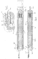
- Said support means consist for example of a tube of circular section accommodating one beside the other said means of control 19, 30, a motor 10 and a reduction gear 22 whose movable axis 104 is provided opening to cooperate with said movable member 2 via of a transmission transmission part 105.
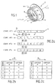
- Said means 4 for creating a signal are constituted, in particular, by a succession of magnet poles 6. These are, possibly evenly distributed.
- said means 4 for creating a signal consist of a bi-polar magnet and / or north and south poles of magnets alternating punctually with each other on a support surface.
- said magnet poles 6 are provided contiguous.
- Said magnets 6 are thus, for example, provided distributed circularly around an axis intended to define the axis of rotation 7 of the movable member 2.
- the succession of north and south poles of magnets 6 is made up, for example, in a known manner, of magnetic rubber, of a strip magnetic, permanent magnets and / or materials that have undergone induction magnetization. It can still be, possibly, materials magnetized molded, overmolded or obtained by sintering according to the shape desired.
- Said succession of north and south poles of magnets 6 is mounted on its support, for example, by gluing, riveting, screwing, overmolding, clipping, embedding or other.
- the means 5 for non-contact detection of signal variations and to identify the direction of description of the period are planned moving while the succession of magnet poles 6 is provided fixed opposite.
- Said means 5 for detecting the signal without contact and for identify the meaning of description of the period consist, for example, of minus two magnetic flux sensors 9a, 9b.
- inductive type Hall effect sensors with reed bulb or others. They may, if necessary, be protected in resin.
- Said sensors 9a, 9b could also, if necessary, be located axially, in particular when said means for creating the signal 4 are located on one and / or the other side of a disc-shaped support, for example centered on said axis of rotation 7.
- sensors 9a, 9b are provided oriented radially and arranged internally.
- said sensors 9a, 9b can then be associated with processing means provided internally in the movable member 2 tubular.
- Said sensors 9a, 9b are, for example, provided spaced apart so as to be able to identify two successions of different signals depending the direction of movement of the movable member 2 and therefore the direction of description of the period of the variations of the magnetic flux.
- FIGs 2b and 2c illustrate as binary information the signals read by the sensors 9a, 9b according to the four stages shown in Figure 2a.
- Table 2b corresponds to a given direction, marked 25, of displacement of the signal creation means 4 while table 2c corresponds to the opposite direction, marked 26.
- monitoring periodic reversals of the flow magnetic can be extended, according to the same principle, beyond the four steps shown in Figures 2a to 2c.
- information noted by the sensors 9a, 9b is for example, translated into electrical impulses, including variations in voltage and / or current, with successive states corresponding to zero or one, depending on the pole present in front of the sensor considered.
- Said means 4 for creating the periodic signal are provided, for example at a ring 3, consisting at least in part of a material capable of undergoing magnetization by induction to define a succession north and / or south poles of magnets, distributed in a ring, along the axis longitudinal of said ring 3.
- Said ring 3 is provided in particular rotating relative to to said support means 100, and provided with means 101 for cooperating with said movable member 2, such as in particular a key, so that its movements are the image of the movements of said movable member 2.
- Said means 5 for detecting variations in the signal and for spot the direction of description of its period are provided, for example, at inside said support means.
- Said means 4 for creating the signal and said means 5 for detect variations in the signal and to identify the direction of description of its period are, in particular, provided at one end of said support means 100, called the first end.
- Said first end is, in particular, provided with a plug 102 for said support means 100.
- a seal 103 is provided between said plug and said support means 100.
- control means further comprise optionally, processing means 30, capable at least of giving a digitized image of the position of said movable member 2 as a function of information recorded by said means 5 to detect variations in the signal and identify the direction of description of its period.
- the absence magnetization can also be assimilated to specific information.
- control means In order to be able to detect arrivals at the end of the race the movable member 2, said control means optionally have, means for comparing the position of said member with positions of limit switches recorded.
- the processing means 30 are provided capable of operate in two different modes, one says "normal” and the other says “Setting”.
- the first authorizes, for example, the monitoring and blocking of the organ mobile when it reaches the saved limit positions while the second authorizes, in particular, the adjustment and / or modification of them.
- electrical means 31 for mode selection the processing means 30 are provided, said means electric 31 being further able to authorize the selection of end positions for their memorization, when the movable member has arrived at the desired position.
- a digitized signal for tracking the positions of the mobile organ, digital processing means and means of electrical selection thus allows, for example, the realization of electrical wiring, allowing remote adjustment of end positions race and facilitating operator interventions.
- Said processing means 30 are provided capable of producing, for example, counting functions from the signal giving the image of the position of the organ. They are provided for this, in particular, with one or more counters.
- Said processing means 30 also allow, by example, comparing the value of the counter (s) with a value corresponding to the end-of-travel positions, these being provided for stored, in particular, in a memory.
- Said processing means 30 also allow, by example, storing the limit values set in said memory and / or the issuance of a blocking order from the movable member in the event of correspondence between the values appearing in the counter (s) and those stored in memory.
- Said processing means 30 are further provided suitable, for example, to authorize a switching of their operation between the “normal” mode and “setting” mode, in particular using data input established from electric current also allowing the setting movement of the mobile organ.
- said processing means 30 carry out so, for example, counting functions, comparison of values counted with the limit values, and issuance of blocking order in match, while in "setting” mode, the comparison of the values counted with the limit values is possibly inhibited and replaced by the news storage function limit values set.
- said processing means 30 take into account counts, for example, the signal or signals giving the image of the position of the mobile organ and / or the signal or signals determining their mode of operation. On exit, they issue, for example, blocking orders of said movable member.
- Said processing means 30 comprise, for example, a microprocessor, capable of implementing software allowing the realization, in particular, of said counting functions, comparison, storage, switching and / or blocking order transmission.
- Said counters consist, for example, of a counter position of the movable member, a limit switch and / or a time counter.
- said selection means 31 are possibly provided capable of adjusting the end of travel positions on the fly, that is to say during the actual movement of the movable member.
- the stored values then correspond, for example, to the counter value after stopping said movable member at the position that you want to save as an end position.
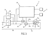
- said drive device comprises, by example, motor means 10 for driving the movable member and / or means 16 for selecting the operating mode of said motor means 10.
- Said means 16 for selecting the operating mode said motor means 10 allow an operator to choose, for example, the direction of movement of said movable member and / or keeping it stationary.
- said processing means 30 are connected by mounting in bypass on a supply line 35 provided between said motor means 10 and said means 16 for selecting the operating mode of said motor means 10.
- Said supply line 35 consists for example of two cables 12a, 12b each allowing the supply of said motor means 10 for operation in a given direction.
- Said means 16 for selecting the operating mode said motor means 10 are, for example, connected to the network, marked 17, and are optionally provided capable of isolating said supply line 35 from this one. This prevents the control device from being permanently powered. In addition, such an arrangement allows, if desired, to control multiple motors from a single control point.
- the means 31 for selecting the operating mode of the means processing 30 and the end position consist of means for simultaneous tensioning of cables 12a, 12b. Said power up is planned temporary. It ceases, for example, when the movable member is arrived at the desired position to define an end position.
- Said motor means consist, in particular, of a motor having, for example, two windings 11a, 11b allowing each rotation in a given direction.
- Said windings 11a, 11b are provided, in particular, between one of the cables 12a, 12b, forming a phase line and a neutral line 13, possibly connected to a common point 14 provided between the said windings 11a, 11b.
- a capacity 15 is, for example, provided at the level of said windings 11a, 11b between their terminals opposite the common point 14.
- Said control means further comprise, by example, blocking means 19 of said motor means 10. They are consisting, in particular, of a circuit breaker member provided on each of the cables 12a, 12b.
- Said means 16 for selecting the operating mode said motor means 10 and / or said means 31 for selecting the mode of operation of the processing means 30 and of the end-of-travel positions consist, for example, of a three-position switch. It is located, in particular, between sector 17 and said supply line 35.
- Said switch could be constituted, for example, for said means 16 for selecting the operating mode of the means motor 10, a blind 18, and for said means 31 of the selection mode processing means 30, a microswitch 20.
- one of the terminals corresponds to a direction of movement of the movable member, the second to the other direction of movement of this and the third at the stop of the engine means.
- a first of the terminals corresponds to the mode for setting a first end position, a second to the setting mode of the second end position and the third terminal in normal operating mode.
- the operator activates the blind 18 to connect the phase line 12a with the sector and allow the displacement of the movable member in the direction concerned. Simultaneously, the other phase line 12b is cut at using the circuit breaker 19 provided thereon.
- the processing means 30 being connected in bypass to said phase lines 12a, 12b, they then note the appearance at the input of a state different from the normal state, each of said lines 12a, 12b being supplied, instead of just one, upstream of the locking means 19.
- the mode limit switch is activated.
- Said drive device further comprises, possibly to promote the functioning of said processing means 30, a stabilized supply between them and said supply line 35.
- Said conversion means comprise, among others, a voltage divider, a rectifier and / or a filter.
- the present invention also relates to a shutter drum rolling, equipped with the drive device described above.
- the motor 10 drives through of the reducer 22 the drum 2 intended to allow the winding / unwinding of the roller shutter deck which is also the subject of the invention.
- Said drum 2, said ring 3 and said piece 105 of transmission are mobile in rotation.
- Said means of cooperation between said ring 3 and said drum 2 consist, in particular, of a groove 107 and a key 108 provided on these items.
Description
La présente invention concerne un dispositif d'entraínement d'un organe tubulaire mobile en rotation bi-directionnellement, un tambour de volet roulant équipé d'un tel dispositif d'entraínement et un volet roulant équipé d'un tel tambour.The present invention relates to a drive device a tubular member movable in bi-directional rotation, a drum roller shutter equipped with such a drive device and a roller shutter equipped of such a drum.
Bien que plus particulièrement prévue pour des applications dans le domaine des volets roulants, l'invention pourra également être utilisée dans tous les domaines de l'activité économique dans lesquels on souhaite entraíner un organe tubulaire mobile en rotation bi-directionnellement.Although more specifically intended for applications in the field of roller shutters, the invention may also be used in all areas of economic activity in which we want drive a tubular member movable in bi-directional rotation.
Actuellement, on connaít des dispositifs permettant de suivre la course d'un organe mobile entraíné selon deux directions opposées. Ils ont pour but, notamment, de détecter l'arrivée de l'organe à un niveau donné afin de pouvoir limiter sa trajectoire entre deux points extrêmes.Currently, we know devices to track the stroke of a movable member driven in two opposite directions. they have in particular, to detect the arrival of the organ at a given level in order to to be able to limit its trajectory between two extreme points.
Dans le domaine des volets roulants, on connaít ainsi, par exemple, des dispositifs d'entraínement équipés de moyens de contrôle mécaniques tels que des jeux de réducteur à engrenage entraínés par le tambour du volet roulant.In the field of roller shutters, we thus know, by example, training devices equipped with control means mechanical such as gear reducer sets driven by the roller shutter drum.
Ceux-ci coopèrent avec différents éléments d'indexage permettant de caractériser la position du tambour et, lorsque celui-i est arrivé en fin de course, d'empêcher sa rotation, à l'aide de systèmes de blocage.These cooperate with different indexing elements to characterize the position of the drum and, when it has arrived at the end of the race, to prevent its rotation, using blocking systems.
Un premier inconvénient de telles solutions est qu'elles nécessitent l'utilisation d'un grand nombre de pièces mécaniques, en contact les unes avec les autres, susceptibles d'usure et posant des problèmes d'étanchéité.A first drawback of such solutions is that they require the use of a large number of mechanical parts in contact with each other, susceptible to wear and causing problems sealing.
On connaít du document EP-A-0.552.459 un dispositif
d'entraínement d'un organe tubulaire, notamment tambour de volet roulant,
mobile en rotation bidirectionnellement autour de son axe longitudinal,
selon le préambule de la revendication 1. We know from document EP-A-0.552.459 a device
for driving a tubular member, in particular a roller shutter drum,
movable in bidirectional rotation about its longitudinal axis,
according to the preamble of
Néanmoins, ce dispositif ne permet pas de constituer des fins de course en tant que tel car il ne permet pas de détecter le sens de variation de l'organe mobile.However, this device does not constitute ends as such because it does not detect the direction of variation of the movable member.
On connaít du document DE-A-43 11 267 un moteur équipé d'une roue magnétique multipolaire apte à coopérer avec deux capteurs pour connaítre la position angulaire du rotor ainsi que le sens de rotation.We know from document DE-A-43 11 267 an engine equipped a multipolar magnetic wheel capable of cooperating with two sensors for know the angular position of the rotor and the direction of rotation.
Néanmoins, cette technique ne peut être utilisée telle quelle sans la présence d'un jeu de réducteurs ni une adaptation spécifique au volet roulant.However, this technique cannot be used as is without the presence of a set of reducers or a specific adaptation to the shutter rolling.
Le but de la présente invention est de proposer un dispositif d'entraínement d'un organe tubulaire, notamment tambour de volet roulant, mobile en rotation bi-directionnellement qui permette de pallier les inconvénients précités et dont les risques d'usure soient diminués.The object of the present invention is to provide a device for driving a tubular member, in particular a roller shutter drum, mobile in bi-directional rotation which allows to overcome aforementioned drawbacks and the risks of wear of which are reduced.
Un autre but de la présente invention est de proposer un dispositif d'entraínement d'un organe tubulaire, notamment tambour de volet roulant, mobile en rotation bi-directionnellement, dans lequel le nombre de pièces mécaniques puisse être limité. Another object of the present invention is to provide a device for driving a tubular member, in particular a flap drum rolling, movable in bi-directional rotation, in which the number of mechanical parts may be limited.
Un autre but de la présente invention est de proposer un dispositif d'entraínement d'un organe tubulaire, notamment tambour de volet roulant, mobile bi-directionnellement, qui puisse être étanche.Another object of the present invention is to provide a device for driving a tubular member, in particular a flap drum rolling, bi-directional mobile, which can be waterproof.
D'autres buts et avantages de l'invention apparaítront au cours de la description qui va suivre qui n'est donnée qu'à titre indicatif et qui n'a pas pour but de la limiter.Other objects and advantages of the invention will become apparent during of the description which follows which is given for information only and which has not to limit it.
La présente invention concerne un dispositif d'entraínement d'un organe tubulaire,
notamment tambour de volet roulant, mobile en rotation bi-directionnellement
autour de son axe longitudinal,
tel que défini dans la revendication 1.The present invention relates to a device for driving a tubular member,
in particular roller shutter drum, movable in bi-directional rotation
around its longitudinal axis,
as defined in
La présente invention concerne en outre un tambour de volet roulant, muni d'un tel dispositif d'entraínement, et un volet roulant muni d'un tel tambour.The present invention further relates to a shutter drum roller, provided with such a drive device, and a roller shutter provided with such drum.
L'invention sera mieux comprise à la lecture de la description suivante, accompagnée des dessins en annexe qui en font partie intégrante et parmi lesquels :
- la figure 1 illustre, en perspective, une pièce d'un exemple de réalisation du dispositif d'entraínement conforme à l'invention,
- les figures 2a à 2c illustrent, sur un exemple, le principe de fonctionnement de la détection des mouvements de l'organe mobile, réalisée selon le dispositif d'entraínement conforme à l'invention,
- la figure 3 illustre, de manière schématique, le câblage du moteur éventuellement utilisé dans le dispositif d'entraínement conforme à l'invention,
- la figure 4 illustre, selon un plan de coupe diamétral, un exemple de dispositif d'entraínement conforme à l'invention,
- la figure 5 illustre, selon un plan de coupe diamétral, un tambour monté sur l'exemple de dispositif d'entraínement de la figure 4 précédente,
- la figure 6 illustre un détail repéré VILS à la figure 5
- FIG. 1 illustrates, in perspective, a part of an exemplary embodiment of the drive device according to the invention,
- FIGS. 2a to 2c illustrate, on an example, the operating principle of the detection of the movements of the movable member, produced according to the drive device according to the invention,
- FIG. 3 schematically illustrates the wiring of the motor possibly used in the drive device according to the invention,
- FIG. 4 illustrates, according to a diametral sectional plane, an example of a drive device according to the invention,
- FIG. 5 illustrates, according to a diametral sectional plane, a drum mounted on the example of the driving device of FIG. 4 above,
- Figure 6 illustrates a detail marked VILS in Figure 5
La présente invention concerne un dispositif d'entraínement d'un organe tubulaire, notamment tambour de volet roulant, mobile en rotation bi-directionnellement.The present invention relates to a drive device a tubular member, in particular roller shutter drum, movable in rotation bidirectionally.
Toutefois, bien que plus particulièrement prévue pour de telles applications, elle pourra tout à fait être utilisée dans tous les autres secteurs de l'activité économique dans lesquels on est amené à entraíner un organe tubulaire mobile en rotation bi-directionnellement.However, although more particularly intended for such applications, it could well be used in all other sectors of the economic activity in which we are led to train an organ tubular mobile in bi-directional rotation.
Comme illustré aux figures 1 et 4 à 6, ledit dispositif comprend,
selon l'invention, un système de contrôle de la position dudit organe mobile 2,
muni de premiers moyens 4 pour créer un signal physique périodique,
notamment un flux magnétique périodique, et de seconds moyens 5 pour
détecter sans contact les variations dudit signal et pour repérer le sens de
description de la période, l'un desdits premiers ou seconds moyens 4, 5 étant
prévu entraíné, directement ou indirectement, par ledit organe mobile 2, et
l'autre desdits premiers ou seconds moyens 4, 5 étant prévu fixe en vis-à-vis. As illustrated in FIGS. 1 and 4 to 6, said device comprises,
according to the invention, a system for controlling the position of said
Grâce au suivi du signal, à la fois en sens et en valeur, il est
ainsi possible de connaítre, à tout moment souhaité, la trajectoire de l'organe
mobile 2, ceci sans engendrer d'usure mécanique au niveau des détecteurs 4,
5 choisis. En effet, la détection du signal choisi peut s'opérer sans contact.Thanks to signal tracking, both in direction and in value, it is
thus possible to know, at any desired time, the trajectory of the organ
mobile 2, this without causing mechanical wear at the level of the
Toujours selon l'invention, ledit dispositif d'entraínement est constitué notamment d'un moyen support destiné à être introduit dans ledit organe mobile pour permettre sa rotation, ledit moyen support, prévu tubulaire, accueillant intérieurement :
- des moyens moteurs pour la rotation dudit organe mobile,
- des moyens de commande desdits moyens moteurs en fonction d'informations provenant au moins dudit système de contrôle de la position de l'organe mobile,
- l'un desdits premier ou second moyens dudit système de contrôle de la position de l'organe mobile,
- motor means for the rotation of said movable member,
- means for controlling said motor means as a function of information originating at least from said system for controlling the position of the movable member,
- one of said first or second means of said system for controlling the position of the movable member,
Comme le montrent les figures 4 et 5, on dispose ainsi d'un
sous-ensemble prêt-à-monter dans ledit organe mobile 2 qui pourra aussi bien
être neuf qu'un organe dont on rénove l'entraínement.As shown in Figures 4 and 5, there is thus a
ready-to-mount sub-assembly in said
De plus, l'utilisation d'un système de détection à distance permet d'assurer l'étanchéité de l'intérieur des moyens support, ce qui est primordial puisqu'ils contiennent les composants électriques et électroniques des moyens moteurs et de commande intégrés dans ledit sous-ensemble.In addition, the use of a remote detection system ensures the sealing of the interior of the support means, which is essential since they contain the electrical and electronic components motor and control means integrated into said sub-assembly.
Lesdits moyens support sont constitués par exemple d'un tube
de section circulaire accueillant les uns à côté des autres lesdits moyens de
commande 19, 30, un moteur 10 et un réducteur 22 dont l'axe mobile 104 est
prévu débouchant pour coopter avec ledit organe mobile 2 par l'intermédiaire
d'une pièce de transmission de l'entraínement 105.Said support means consist for example of a tube
of circular section accommodating one beside the other said means of
Lesdits moyens 4 pour créer un signal sont constitués,
notamment, par une succession de pôles d'aimants 6. Ceux-ci sont,
éventuellement, répartis régulièrement.Said means 4 for creating a signal are constituted,
in particular, by a succession of
Il s'agit, notamment, d'une alternance de pôles nord et sud ou encore d'une alternance de pôles nord et/ou sud et de zones non magnétiques.These include, in particular, an alternation of north and south poles or still alternating north and / or south poles and non-magnetic zones.
Selon un premier exemple de réalisation, non illustré, lesdits moyens 4 pour créer un signal sont constitués d'un aimant bi-polaire et/ou de pôles nord et sud d'aimants alternant ponctuellement les uns avec les autres sur une surface support.According to a first example of embodiment, not illustrated, said means 4 for creating a signal consist of a bi-polar magnet and / or north and south poles of magnets alternating punctually with each other on a support surface.
Selon un autre mode de réalisation, correspondant notamment
à celui illustré, lesdits pôles d'aimants 6 sont prévus jointifs.According to another embodiment, corresponding in particular
to that illustrated, said
Lesdits aimants 6 sont ainsi, par exemple, prévus répartis de
manière circulaire autour d'un axe destiné à définir l'axe de rotation 7 de
l'organe mobile 2.Said
La succession de pôles nord et sud d'aimants 6 est constituée,
par exemple, de manière connue, de caoutchouc magnétique, d'une bande
magnétique, d'aimants permanents et/ou de matériaux ayant subi une
aimantation par induction. Il peut encore s'agir, éventuellement, de matières
aimantées moulées, surmoulées ou obtenues par frittage selon la forme
voulue.The succession of north and south poles of
Ladite succession de pôles nord et sud d'aimants 6 est montée
sur son support, par exemple, par collage, rivetage, vissage, surmoulage,
clipsage, encastrement ou autres.Said succession of north and south poles of
Selon le mode de réalisation illustré, il s'agit d'une couronne de
caoutchouc magnétique collée à l'intérieur de ladite pièce mécanique 3.According to the illustrated embodiment, it is a crown of
magnetic rubber bonded to the interior of said
Selon un premier mode de réalisation, les moyens 5 pour
détecter sans contact les variations du signal et pour repérer le sens de
description de la période sont prévus mobiles tandis que la succession de
pôles d'aimants 6 est prévue fixe en vis-à-vis.According to a first embodiment, the
Selon un autre mode de réalisation, correspondant notamment à celui illustré, cela pourra être le contraire, comme cela est développé plus loin.According to another embodiment, corresponding in particular to that illustrated, it could be the opposite, as it is developed more far.
Lesdits moyens 5 pour détecter sans contact le signal et pour
repérer le sens de description de la période sont constitués, par exemple, d'au
moins deux capteurs 9a, 9b de flux magnétique.Said means 5 for detecting the signal without contact and for
identify the meaning of description of the period consist, for example, of
minus two
Ceux-ci détectent la variation périodique du champ magnétique
engendré par ladite succession de pôles nord et sud d'aimants 6, prévus en
vis-à-vis.These detect the periodic variation of the magnetic field
generated by said succession of north and south poles of
Il s'agit, notamment, de capteurs de type inductif, à effet Hall, à ampoule reed ou autres. Ils pourront, éventuellement, être protégés dans de la résine.These are, in particular, inductive type Hall effect sensors with reed bulb or others. They may, if necessary, be protected in resin.
Ils sont disposés, notamment, radialement, intérieurement et/ou extérieurement auxdits moyens de création 4 du signal lorsque ceux-ci sont par exemple prévus en anneaux.They are arranged, in particular, radially, internally and / or externally to said signal creation means 4 when these are for example provided in rings.
Lesdits capteurs 9a, 9b pourront encore, éventuellement, être
situés axialement, notamment lorsque lesdits moyens de création du signal 4
sont situés sur l'une et/ou l'autre faces d'un support en forme de disque, par
exemple centré sur ledit axe de rotation 7.Said
Selon le mode de réalisation illustré, ils sont prévus orientés
radialement et disposés intérieurement. Une telle solution permet, entre autres
de limiter l'encombrement, lesdits capteurs 9a, 9b pouvant alors être associés à
des moyens de traitement prévus intérieurement dans l'organe mobile 2
tubulaire.According to the illustrated embodiment, they are provided oriented
radially and arranged internally. Such a solution allows, among other things
limit the size, said
Lesdits capteurs 9a, 9b sont, par exemple, prévus espacés de
manière à pouvoir repérer deux successions de signaux différents en fonction
du sens de déplacement de l'organe mobile 2 et donc du sens de description
de la période des variations du flux magnétique.Said
Comme illustré à la figure 2a où la succession de pôles nord et
sud d'aimants 6 a été représentée de manière rectiligne dans quatre étapes
successives, la disposition des capteurs 9a, 9b est réalisée de façon à ce que
l'un et l'autre reçoivent une information magnétique s'alternant de manière
distincte.As illustrated in Figure 2a where the succession of north and
south of
Pour cela, ils sont mis, notamment, soit côte à côte, soit à des distances calculées afin de pouvoir, dans une première position, se trouver simultanément en vis-à-vis d'un ou de pôles de même nature, soit nord, soit sud, et dans une deuxième position, se trouver simultanément en vis-à-vis de deux pôles de natures différentes.For this, they are put, in particular, either side by side or at distances calculated in order to be able, in a first position, to be simultaneously facing one or more poles of the same nature, either north or south, and in a second position, to be simultaneously opposite two poles of different natures.
Les figures 2b et 2c illustrent sous forme d'informations binaires
les signaux lus par les capteurs 9a, 9b en fonction des quatre étapes
représentées à la figure 2a.Figures 2b and 2c illustrate as binary information
the signals read by the
Le tableau 2b correspond à un sens donné, repéré 25, de déplacement des moyens de création 4 du signal tandis que le tableau 2c correspond au sens opposé, repéré 26.Table 2b corresponds to a given direction, marked 25, of displacement of the signal creation means 4 while table 2c corresponds to the opposite direction, marked 26.
Naturellement, le suivi des inversions périodiques du flux magnétique peut être étendu, selon le même principe, au-delà des quatre étapes représentées aux figures 2a à 2c.Naturally, monitoring periodic reversals of the flow magnetic can be extended, according to the same principle, beyond the four steps shown in Figures 2a to 2c.
On constate que l'on effectue bien ainsi à la fois un repérage
de la position desdits moyens 4 de création du signal et par suite de leur
support et donc dudit organe mobile 2, ainsi qu'un repérage du sens de rotation
de ce dernier.We see that we do well both a location
of the position of said means 4 for creating the signal and as a result of their
support and therefore of said
A ce sujet, concernant la lecture des signaux, l'information
relevée par les capteurs 9a, 9b est par exemple, traduite sous forme
d'impulsions électriques, notamment des variations de tension et/ou de
courant, avec des états successifs correspondant à zéro ou un, en fonction du
pôle présent en face du capteur considéré.On this subject, concerning the reading of signals, information
noted by the
Lesdits moyens 4 pour créer le signal périodique sont prévus,
par exemple au niveau d'une bague 3, constituée au moins en partie d'un
matériau apte à subir une aimantation par induction pour définir une succession
de pôles nord et/ou sud d'aimants, répartis en couronne, selon l'axe
longitudinal de ladite bague 3.Said means 4 for creating the periodic signal are provided,
for example at a
Ladite bague 3 est prévue notamment tournante par rapport
audit moyen support 100, et munie de moyens 101 pour coopérer avec ledit
organe mobile 2, tels que notamment une clavette, de manière à ce que ses
mouvements soient l'image des mouvements dudit organe mobile 2.Said
Lesdits moyens 5 pour détecter les variations du signal et pour repérer le sens de description de sa période sont prévue, par exemple, à l'intérieur dudit moyen support.Said means 5 for detecting variations in the signal and for spot the direction of description of its period are provided, for example, at inside said support means.
Lesdits moyens 4 pour créer le signal et lesdits moyens 5 pour
détecter les variations du signal et pour repérer le sens de description de sa
période sont, notamment, prévues à l'une des extrémités dudit moyen support
100, dite première extrémité.Said means 4 for creating the signal and said
Ladite première extrémité est, notamment, munie d'un bouchon 102 pour ledit moyen support 100. Un joint d'étanchéïté 103 est prévu entre ledit bouchon et ledit moyen support 100.Said first end is, in particular, provided with a plug 102 for said support means 100. A seal 103 is provided between said plug and said support means 100.
L'étanchéïté de cette disposition est alors indépendante des premiers (4) et seconds (5) moyens dudit système de contrôle de la position de l'organe mobile.The watertightness of this arrangement is then independent of first (4) and second (5) means of said position control system the mobile organ.
Les moyens de commande comprennent, en outre,
éventuellement, des moyens de traitement 30, aptes au moins à donner une
image numérisée de la position dudit organe mobile 2 en fonction des
informations relevées par lesdits moyens 5 pour détecter les variations du
signal et repérer le sens de description de sa période.The control means further comprise
optionally, processing means 30, capable at least of giving a
digitized image of the position of said
Dans le cas de l'utilisation d'un capteur bi-polaire, l'absence d'aimantation pourra également être assimilée à une information spécifique.In the case of the use of a bi-polar sensor, the absence magnetization can also be assimilated to specific information.
Selon un autre mode de réalisation alternatif, non illustré, il pourra également être prévu d'utiliser une série de capteurs, formant notamment une couronne, en vis-à-vis de pôles magnétiques nord et sud, éventuellement fixes.According to another alternative embodiment, not illustrated, it provision may also be made to use a series of sensors, forming in particular a crown, facing north and south magnetic poles, possibly fixed.
De manière à pouvoir détecter les arrivées en fin de course de
l'organe mobile 2, lesdits moyens de commande présentent, éventuellement,
des moyens de comparaison de la position dudit organe avec des positions de
fin de course enregistrées.In order to be able to detect arrivals at the end of the race
the
En outre, afin de faciliter ses utilisations, ils pourront être munis de moyens de réglage et d'enregistrement desdites positions de fin de course.In addition, in order to facilitate its use, they may be provided means for adjusting and recording said end of travel positions.
Pour cela, les moyens de traitement 30 sont prévus aptes à fonctionner selon deux modes différents, l'un dit « normal » et l'autre dit de « réglage ». Le premier autorise, par exemple, le suivi et le blocage de l'organe mobile lorsqu'il arrive au niveau des positions de fin de course enregistrées tandis que le second autorise, notamment, le réglage et/ou la modification de celles-ci.For this, the processing means 30 are provided capable of operate in two different modes, one says "normal" and the other says "Setting". The first authorizes, for example, the monitoring and blocking of the organ mobile when it reaches the saved limit positions while the second authorizes, in particular, the adjustment and / or modification of them.
En outre, des moyens électriques 31 de sélection du mode d'utilisation des moyens de traitement 30 sont prévus, lesdits moyens électriques 31 étant aptes en outre à autoriser la sélection des positions de fin de course pour leur mémorisation, lorsque l'organe mobile est arrivé à la position désirée.In addition, electrical means 31 for mode selection the processing means 30 are provided, said means electric 31 being further able to authorize the selection of end positions for their memorization, when the movable member has arrived at the desired position.
L'utilisation d'un signal numérisé pour le suivi des positions de l'organe mobile, de moyens numériques de traitement et de moyens de sélection de nature électrique permet ainsi, par exemple, la réalisation de câblages électriques, autorisant le réglage à distance des positions de fin de course et facilitant les interventions des opérateurs.The use of a digitized signal for tracking the positions of the mobile organ, digital processing means and means of electrical selection thus allows, for example, the realization of electrical wiring, allowing remote adjustment of end positions race and facilitating operator interventions.
Lesdits moyens de traitement 30 sont prévus aptes à réaliser, par exemple, des fonctions de comptage à partir du signal donnant l'image de la position de l'organe. Ils sont munis pour cela, notamment, d'un ou plusieurs compteurs.Said processing means 30 are provided capable of producing, for example, counting functions from the signal giving the image of the position of the organ. They are provided for this, in particular, with one or more counters.
Lesdits moyens de traitement 30 permettent également, par exemple, la comparaison de la valeur du ou des compteurs avec une valeur correspondant aux positions de fin de course, celles-ci étant prévues stockées, notamment, dans une mémoire.Said processing means 30 also allow, by example, comparing the value of the counter (s) with a value corresponding to the end-of-travel positions, these being provided for stored, in particular, in a memory.
Lesdits moyens de traitement 30 permettent encore, par exemple, le stockage des valeurs de fin de course réglées dans ladite mémoire et/ou l'émission d'ordre de blocage de l'organe mobile en cas de correspondance entre les valeurs figurant dans le ou les compteurs et celles stockées dans la mémoire.Said processing means 30 also allow, by example, storing the limit values set in said memory and / or the issuance of a blocking order from the movable member in the event of correspondence between the values appearing in the counter (s) and those stored in memory.
Lesdits moyens de traitement 30 sont en outre prévus aptes, par exemple, à autoriser une commutation de leur fonctionnement entre le mode « normal » et le mode « réglage », notamment en utilisant des données d'entrée établies à partir de courant électrique permettant également la mise en mouvement de l'organe mobile.Said processing means 30 are further provided suitable, for example, to authorize a switching of their operation between the “normal” mode and “setting” mode, in particular using data input established from electric current also allowing the setting movement of the mobile organ.
En mode « normal », lesdits moyens de traitement 30 réalisent ainsi, par exemple, les fonctions de comptage, comparaison des valeurs comptées avec les valeurs de fin de course, et émission d'ordre de blocage en cas de correspondance, tandis qu'en mode « réglage », la fonction de comparaison des valeurs comptées avec les valeurs de fin de course est éventuellement inhibée et remplacée par la fonction de stockage des nouvelles valeurs de fin de course réglées.In “normal” mode, said processing means 30 carry out so, for example, counting functions, comparison of values counted with the limit values, and issuance of blocking order in match, while in "setting" mode, the comparison of the values counted with the limit values is possibly inhibited and replaced by the news storage function limit values set.
Ainsi, en entrée, lesdits moyens de traitement 30 prennent en compte, par exemple, le ou les signaux donnant l'image de la position de l'organe mobile et/ou le ou les signaux déterminant leur mode de fonctionnement. En sortie, ils émettent, par exemple, les ordres de blocage dudit organe mobile.Thus, at input, said processing means 30 take into account counts, for example, the signal or signals giving the image of the position of the mobile organ and / or the signal or signals determining their mode of operation. On exit, they issue, for example, blocking orders of said movable member.
Lesdits moyens de traitement 30 comprennent, par exemple, un microprocesseur, apte à mettre en oeuvre un logiciel permettant la réalisation, notamment, desdites fonctions de comptage, comparaison, stockage, commutation et/ou d'émission d'ordre de blocage.Said processing means 30 comprise, for example, a microprocessor, capable of implementing software allowing the realization, in particular, of said counting functions, comparison, storage, switching and / or blocking order transmission.
Lesdits compteurs sont constitués, par exemple, d'un compteur de position de l'organe mobile, d'un compteur de fin de course et/ou d'un compteur de temps.Said counters consist, for example, of a counter position of the movable member, a limit switch and / or a time counter.
Afin d'éviter le réglage des positions de fin de course par une indication brute et théorique des valeurs de compteur pour lesquelles l'organe mobile doit être bloqué, lesdits moyens de sélection 31 sont éventuellement prévus aptes à permettre le réglage des positions de fin de course à la volée, c'est-à-dire lors du déplacement réel de l'organe mobile.In order to avoid the adjustment of the end positions by a raw and theoretical indication of the counter values for which the device mobile must be blocked, said selection means 31 are possibly provided capable of adjusting the end of travel positions on the fly, that is to say during the actual movement of the movable member.
Les valeurs mémorisées correspondent alors, par exemple, à la valeur du compteur après l'arrêt dudit organe mobile au niveau de la position que l'on souhaite enregistrer en tant que position de fin de course.The stored values then correspond, for example, to the counter value after stopping said movable member at the position that you want to save as an end position.
Cela étant, ledit dispositif d'entraínement comprend, par exemple, des moyens moteur 10 d'entraínement de l'organe mobile et/ou des moyens de sélection 16 du mode de fonctionnement desdits moyens moteur 10.However, said drive device comprises, by example, motor means 10 for driving the movable member and / or means 16 for selecting the operating mode of said motor means 10.
Lesdits moyens de sélection 16 du mode de fonctionnement desdits moyens moteur 10 permettent à un opérateur de choisir, par exemple, le sens de déplacement dudit organe mobile et/ou le maintien à l'arrêt de celui-ci.Said means 16 for selecting the operating mode said motor means 10 allow an operator to choose, for example, the direction of movement of said movable member and / or keeping it stationary.
Selon un mode de réalisation de l'invention correspondant à
celui illustré, lesdits moyens de traitement 30 sont connectés par montage en
dérivation sur une ligne d'alimentation 35 prévue entre lesdits moyens moteur
10 et lesdits moyens de sélection 16 du mode de fonctionnement desdits
moyens moteur 10.According to an embodiment of the invention corresponding to
that illustrated, said processing means 30 are connected by mounting in
bypass on a
Ladite ligne d'alimentation 35 est constituée par exemple, de
deux câbles 12a, 12b permettant chacun l'alimentation desdits moyens moteur
10 pour un fonctionnement selon un sens donné.Said
Lesdits moyens de sélection 16 du mode de fonctionnement
desdits moyens moteur 10 sont, par exemple, connectés au réseau, repéré 17,
et sont, éventuellement, prévus aptes à isoler ladite ligne d'alimentation 35 de
celui-ci. On évite ainsi que le dispositif de contrôle soit en permanence
alimenté. De plus, une telle disposition permet, si désirée, de contrôler
plusieurs moteurs à partir d'un point de commande unique.Said means 16 for selecting the operating mode
said motor means 10 are, for example, connected to the network, marked 17,
and are optionally provided capable of isolating said
Pour permettre le réglage desdites positions de fin de course,
les moyens de sélection 31 du mode de fonctionnement des moyens de
traitement 30 et de la position de fin de course sont constitués de moyens de
mise sous tension simultanée des câbles 12a, 12b. Ladite mise sous tension
est prévue temporaire. Elle cesse, par exemple, lorsque l'organe mobile est
arrivé à la position désirée pour définir une position de fin de course.To allow the adjustment of said end positions,
the
Il s'agit, notamment, desdits moyens de sélection 16 du mode de fonctionnement des moyens moteur 10 prévus, par exemple, dédoublés en parallèle.These are, in particular, said mode selection means 16 of operation of the motor means 10 provided, for example, split into parallel.
On peut ainsi disposer de quatre états différents à l'entrée des moyens de traitement 30 permettant alternativement le passage de ces derniers entre le mode de fonctionnement « normal » et le mode de fonctionnement « réglage », ceci pour chacun des sens de déplacement de l'organe mobile, et autorisant le réglage des positions de fin de course aux extrémités de sa trajectoire.We can thus have four different states at the input of processing means 30 alternately allowing the passage of these between the "normal" operating mode and the "adjustment" operation, this for each direction of movement of the movable member, and authorizing the adjustment of the end-of-travel positions ends of its trajectory.
Lesdits moyens moteur sont constitués, notamment, d'un
moteur présentant, par exemple, deux enroulements 11a,11b permettant
chacun sa rotation dans un sens donné.Said motor means consist, in particular, of a
motor having, for example, two
Lesdits enroulements 11a, 11b, sont prévus, notamment, entre
un des câbles 12a, 12b, formant une ligne de phase et une ligne de neutre 13,
éventuellement connectée à un point commun 14 prévu entre lesdits
enroulements 11a, 11b.Said
Une capacité 15 est, par exemple, prévue au niveau desdits
enroulements 11a, 11b entre leurs bornes opposées au point commun 14.A
Lesdits moyens de commande comprennent en outre, par
exemple, des moyens de blocage 19 desdits moyens moteur 10. Ils sont
constitués, notamment, d'un organe coupe circuit prévu sur chacun des câbles
12a, 12b.Said control means further comprise, by
example, blocking means 19 of said motor means 10. They are
consisting, in particular, of a circuit breaker member provided on each of the
Ils sont prévus aptes à être déclenchés, par exemple, à partir de l'ordre de blocage éventuellement émis par lesdits moyens de traitement 30.They are designed to be triggered, for example, from the blocking order possibly issued by said processing means 30.
Lesdits moyens de sélection 16 du mode de fonctionnement
desdits moyens moteur 10 et/ou lesdits moyens de sélection 31 du mode de
fonctionnement des moyens de traitement 30 et des positions de fin de course
sont constitués, par exemple, d'un commutateur à trois positions. Celui-ci est
situé, notamment, entre le secteur 17 et ladite ligne d'alimentation 35.Said means 16 for selecting the operating mode
said motor means 10 and / or said means 31 for selecting the mode of
operation of the processing means 30 and of the end-of-travel positions
consist, for example, of a three-position switch. It is
located, in particular, between
Ledit commutateur pourra être constitué, par exemple, pour
lesdits moyens 16 de sélection du mode de fonctionnement des moyens
moteur 10, d'un borgnier 18, et pour lesdits moyens 31 du mode de sélection
des moyens de traitement 30, d'un micro-interrupteur 20.Said switch could be constituted, for example, for
said means 16 for selecting the operating mode of the
Ils présentent chacun, notamment, une borne reliée au secteur
17 et trois bornes reliables à la ligne d'alimentation 35.They each have, in particular, a terminal connected to the
Pour le borgnier 18, l'une des bornes correspond à un sens de déplacement de l'organe mobile, la seconde à l'autre sens de déplacement de celui-ci et la troisième à l'arrêt des moyens moteur.For the blind 18, one of the terminals corresponds to a direction of movement of the movable member, the second to the other direction of movement of this and the third at the stop of the engine means.
Pour le micro-interrupteur 20, une première des bornes
correspond au mode de réglage d'une première position de fin de course, une
seconde au mode de réglage de la seconde position de fin de course et la
troisième borne au mode de fonctionnement normal.For
A titre d'exemple, pour régler l'une des valeurs de fin de
course, l'opérateur actionne le borgnier 18 pour connecter la ligne de phase
12a avec le secteur et permettre le déplacement de l'organe mobile dans la
direction concernée. Simultanément, l'autre ligne de phase 12b est coupée à
l'aide du coupe circuit 19 prévu sur celle-ci.For example, to set one of the end values of
stroke, the operator activates the blind 18 to connect the
L'opérateur actionne ensuite le micro-interrupteur 20 de
manière à connecter le secteur et l'autre ligne de phase 12b.The operator then actuates the
Les moyens de traitement 30 étant branchés en dérivation sur
lesdites lignes de phase 12a, 12b, ils constatent alors l'apparition en entrée
d'un état différent de l'état normal, chacune desdites lignes 12a, 12b étant
alimentée, au lieu d'une seule, en amont des moyens de blocage 19. Le mode
de réglage des fins de course est ainsi actionné.The processing means 30 being connected in bypass to
said
Lorsque l'opérateur juge que l'organe mobile, continuant sa
course, aura atteint le point extrême désiré, il pourra alors basculer le borgnier
18 et/ou le micro-interrupteur 20 sur la position correspondant à l'arrêt du
moteur et/ou au mode de fonctionnement normal tandis que le microprocesseur
coupera le moteur et mettra en mémoire la valeur du compteur relevée.When the operator judges that the movable member, continuing its
race, will have reached the desired extreme point, it will then be able to tip the blind
18 and / or the
Pour le réglage de la position de fin de course opposé, les opérations sont inversées.To adjust the opposite end position, the operations are reversed.
On constate que l'on réalise bien ainsi un réglage à distance de la position des fins de course et que l'on peut donc éviter toute intervention sur l'organe mobile lui-même.It can be seen that a remote adjustment of the position of the limit switches and that we can therefore avoid any intervention on the movable organ itself.
Ledit dispositif d'entraínement comprend en outre,
éventuellement, pour favoriser le fonctionnement desdits moyens de traitement
30, une alimentation stabilisée entre ceux-ci et ladite ligne d'alimentation 35.Said drive device further comprises,
possibly to promote the functioning of said processing means
30, a stabilized supply between them and said
Il comprend en outre, éventuellement, des moyens de conversion analogique/numérique prévus entre lesdits moyens de traitement numériques 30 et lesdits moyens de sélection 31 du mode de fonctionnement desdits moyens de traitement 30. Lesdits moyens de conversion comprennent, entre autres, un diviseur de tension, un redresseur et/ou un filtre.It also includes, possibly, means of analog / digital conversion provided between said processing means digital 30 and said means 31 for selecting the operating mode said processing means 30. Said conversion means comprise, among others, a voltage divider, a rectifier and / or a filter.
La présente invention concerne également un tambour de volet roulant, équipé du dispositif d'entraínement décrit ci-dessus.The present invention also relates to a shutter drum rolling, equipped with the drive device described above.
Comme déjà évoqué, le moteur 10 entraíne par l'intermédiaire
du réducteur 22 le tambour 2 destiné à permettre l'enroulement/déroulement du
tablier du volet roulant faisant également l'objet de l'invention.As already mentioned, the
Le moyen support 100, le bouchon 102 et les éléments prévus à l'intérieur dudit moyen support, à l'exception du rotor du moteur et du réducteur sont prévus fixes.The support means 100, the plug 102 and the elements provided inside said support means, with the exception of the motor rotor and the reducer are provided fixed.
Ledit tambour 2, ladite bague 3 et ladite pièce 105 de
transmission sont mobiles en rotation.Said
Lesdits moyens de coopération entre ladite bague 3 et ledit
tambour 2 sont constitués, notamment, d'une rainure 107 et d'une clavette 108
prévues sur ces éléments.Said means of cooperation between said
Naturellement, d'autres modes de mise en oeuvre à la portée de l'homme de l'art, auraient pu être envisagés sans pour autant sortir du cadre de l'invention, tel que défini dans les revendications.Naturally, other methods of implementation within reach skilled in the art, could have been envisaged without departing from the scope of the invention, as defined in the claims.
Claims (12)
- A driving system for a tubular member (2), notably a roller blind drum, mobile in bi-directional rotation around its longitudinal axis, comprising motorised means (10, 22) for the rotation of said mobile element (2), means (19, 30) for controlling said motorised means in relation to information issued from at least said position control system of the mobile element, and a system for controlling the position of said mobile element (2), said system including first means (4) for creating a periodic physical signal and second means (5) for detecting the variations of said signal without any contact, whereas one of said first or second means (4, 5) is provided to be driven, directly or indirectly, by said mobile element (2) and the other of said first or second means (4, 5) is provided to be fixed and opposite,
characterised in that said driving device is composed of a supporting means (100) intended to be inserted into said mobile element (2) to enable the rotation thereof, whereas said supporting means (100) provided as tubular, houses internally said motorised means (10, 22), said control means (19, 30) and one (5) of said first or second means of said position control system of the mobile element,
in that the other (4) of said first or second means is mounted, opposite, mobile in rotation, around said tubular supporting means (100) in order to be able to co-operate with said mobile element (2),
and in that the first and second means (4, 5) are able to locate the description direction of the period. - A device according to claim 1, characterised in that said first means (4) are mounted, mobile in rotation around said supporting tubular means (100) and are composed of a succession of magnetic poles (6) distributed in a circular fashion around an axis intended to define the rotational axis (7) of the mobile element (2), said second means (5) for detecting without any contact the signal and for locating the description direction of the period are composed of at least two magnetic flux sensors (9a, 9b) spaced in order to locate two successions of different signals relative to the displacement direction of the mobile element (2), said first means (4) intended for creating the signal being provided close to a ring (3) formed of a succession of north/south magnetic poles, distributed in a crown pattern, along the longitudinal axis of the ring, said ring (3) being provided to rotate relative to said tubular means (100), said sensors (9a, 9b) being arranged inside said ring (3).
- A device according to claim 2, wherein said magnets (6) are distributed regularly and/or are provided as contiguous.
- A device according to claim 1, wherein said sensors (9a, 9b) are arranged radially, internally and/or externally to said signal creation means (4) and/or axially.
- A device according to claim 2, wherein said signal creation means (4) are provided close to the ring (3), composed at least partially of a material capable to be subjected to induction magnetisation in order to define a succession of north and/or south magnetic poles, distributed in a crown pattern, along the longitudinal axis of said ring (3).
- A device according to claim 2, wherein said ring (3) is fitted with means (101) intended to co-operate with said mobile element (2) so that the movement thereof reflect the movements of said mobile element (2).
- A device according to claim 6, wherein said means (5) intended to detection the variations of the signal and to locate the description direction of its period are provided inside said supporting means.
- A device according to claims 1 or 7, wherein said signal creation means (4) and said means (5) intended for detecting the signal variations and for locating the description direction of its period are provided at one of its ends of said supporting means (100), so-called first end.
- A device according to claim 8, wherein said first end is fitted with a plug (102) for said supporting means (100).
- A device according to claim 9, wherein a sealing joint (103) is provided between said plug and said supporting means (100).
- A roller blind drum fitted with a driving device according to claim 1.
- A roller blind, fitted with the drum according to claim 11.
Applications Claiming Priority (2)
| Application Number | Priority Date | Filing Date | Title |
|---|---|---|---|
| FR9807944 | 1998-06-19 | ||
| FR9807944A FR2780090B1 (en) | 1998-06-19 | 1998-06-19 | DEVICE FOR DRIVING AN ORGAN, ESPECIALLY A ROLLING SHUTTER, AND AN OPENING PROTECTION DEVICE, ESPECIALLY ROLLING SHUTTER, EQUIPPED WITH A DRIVING DEVICE |
Publications (2)
| Publication Number | Publication Date |
|---|---|
| EP0965724A1 EP0965724A1 (en) | 1999-12-22 |
| EP0965724B1 true EP0965724B1 (en) | 2004-10-06 |
Family
ID=9527760
Family Applications (1)
| Application Number | Title | Priority Date | Filing Date |
|---|---|---|---|
| EP99490016A Expired - Lifetime EP0965724B1 (en) | 1998-06-19 | 1999-06-18 | Driving device for a bi-directionally rotatable tubular roll, drum of roller shutter equipped with such driving device, roller shutter equipped with such winding drum |
Country Status (3)
| Country | Link |
|---|---|
| EP (1) | EP0965724B1 (en) |
| DE (1) | DE69920807T2 (en) |
| FR (1) | FR2780090B1 (en) |
Families Citing this family (8)
| Publication number | Priority date | Publication date | Assignee | Title |
|---|---|---|---|---|
| FR2821885B1 (en) * | 2001-03-12 | 2007-04-13 | Bubendorff Volet Roulant | DEVICE FOR FASTENING THE HEAD OF A TUBULAR SHUTTERBOARD MOTOR |
| FR2862334B1 (en) | 2003-11-19 | 2006-02-10 | Somfy | DEVICE FOR DRIVING A CLOSURE OR SOLAR PROTECTION SCREEN AND INSTALLATION COMPRISING SUCH A DEVICE |
| FR2869349B1 (en) * | 2004-04-26 | 2008-01-04 | Jouvence Sarl | METHOD FOR CONTROLLING THE MOVEMENT OF A ROLLING SHUTTER APRON AND DEVICE FOR IMPLEMENTING THE METHOD |
| WO2006008218A1 (en) * | 2004-07-23 | 2006-01-26 | Jolly Motor International S.P.A. | Detector of angular position for driving devices with incorporated tubular gear motor for roller shutters |
| DE602005003354T2 (en) * | 2005-08-09 | 2008-09-11 | Alcatel Lucent | Drive unit for objects that are wound up and unwound on a pipe |
| ES2275426B2 (en) * | 2005-10-07 | 2009-02-01 | Joan Ventayol I Pinyol | DEVICE FOR CONTROLLING THE POSITION OF A CURTAIN, PERSONAL OR TOLDING AND THE MEANS OF DRIVING OF SUCH DEVICE. |
| DE202007016283U1 (en) * | 2007-11-13 | 2009-03-26 | Arca Beteiligungen Gmbh | Drive arrangement for a darkening device |
| DE202010003095U1 (en) * | 2010-03-02 | 2011-11-16 | Arca Beteiligungen Gmbh | Tubular motor arrangement for a darkening device |
Family Cites Families (8)
| Publication number | Priority date | Publication date | Assignee | Title |
|---|---|---|---|---|
| DE3346242A1 (en) * | 1983-12-21 | 1985-07-04 | Kurt Schlattingen Kunz | Method for driving a window-shutter drive motor, and a controller for carrying out the method |
| FR2673234A1 (en) * | 1991-02-26 | 1992-08-28 | Kraemer Thierry | Device for monitoring the operation of automatic doors |
| DE4201971A1 (en) * | 1992-01-22 | 1993-08-05 | Wilhelm Rademacher | DARKENING DEVICE |
| DE4311267A1 (en) * | 1993-04-06 | 1994-10-20 | Tornado Antriebstech Gmbh | Position sensor |
| DE4414280A1 (en) * | 1994-04-23 | 1995-10-26 | Bosch Gmbh Robert | Device for detecting the rotational movement of a toothed or cam wheel |
| DE4440449C2 (en) * | 1994-11-14 | 1997-06-12 | Elero Antrieb Sonnenschutz | Method and device for controlling the standstill of electric motor-operated shutters or the like |
| EP0770757B2 (en) * | 1995-10-28 | 2010-12-15 | elero GmbH | Method of actuating awnings or the like by an electric motor |
| DE19630491C1 (en) * | 1996-07-29 | 1998-02-05 | Selve Ernst Gmbh Co Kg | Circuit arrangement for controlling electromotive drives for curtains that can be wound up and unwound |
-
1998
- 1998-06-19 FR FR9807944A patent/FR2780090B1/en not_active Expired - Fee Related
-
1999
- 1999-06-18 DE DE69920807T patent/DE69920807T2/en not_active Expired - Lifetime
- 1999-06-18 EP EP99490016A patent/EP0965724B1/en not_active Expired - Lifetime
Also Published As
| Publication number | Publication date |
|---|---|
| FR2780090A1 (en) | 1999-12-24 |
| DE69920807T2 (en) | 2005-10-13 |
| DE69920807D1 (en) | 2004-11-11 |
| EP0965724A1 (en) | 1999-12-22 |
| FR2780090B1 (en) | 2000-08-11 |
Similar Documents
| Publication | Publication Date | Title |
|---|---|---|
| EP0162780B1 (en) | Apparatus for detecting the angular position of the rotor in a rotating machine | |
| EP0965724B1 (en) | Driving device for a bi-directionally rotatable tubular roll, drum of roller shutter equipped with such driving device, roller shutter equipped with such winding drum | |
| FR2947902A1 (en) | ABSOLUTE AND MULTI-PERIODIC POSITION SENSOR | |
| FR2891962A1 (en) | DEVICE FOR DETERMINING THE EFFECTIVE INVERSION OF THE ROTATION DIRECTION OF A REVERSIBLE ROTARY DRIVE. | |
| FR2470477A1 (en) | DIRECT CURRENT MOTOR WITHOUT BRUSH | |
| FR3032475A1 (en) | ||
| FR2488997A3 (en) | Rotational speed and angle detector for engine crankshaft - uses inductive sensor to detect passage of magnetic reference tooth on starter ring gear | |
| EP3171231B1 (en) | Shock detector circuit and operating method thereof | |
| FR2820252A1 (en) | BRUSHLESS MOTOR CONTROL SYSTEM | |
| FR2844591A1 (en) | Equipment for determining the lateral displacement of a shaft, comprises axially mobile motor shaft, a multiple pole magnet and a sensor which detects patterns of north and south poles | |
| EP2966414A1 (en) | Mounting of a system for determining angular position on a rotating member | |
| EP0189732B1 (en) | Driving device for an electric motor with permanent magnetized rotor | |
| FR2703450A1 (en) | Absolute incremental numerical encoder, installation and machine comprising this encoder | |
| EP1404016B1 (en) | Device for controlling an electronically-commutated motor comprising angularly distributed singularities | |
| WO2004084402A1 (en) | Switching device, anti-friction bearing and electric motor using one such device | |
| EP0194911B1 (en) | Displacement measuring apparatus with a code wheel | |
| FR3028942A1 (en) | INDUCTIVE SENSOR FOR MEASURING THE POSITION OF A TREE OF A VEHICLE | |
| EP4042113A1 (en) | Method for detecting an absolute angular position or an absolute angular movement path of a rotating member | |
| FR2479451A1 (en) | DISPLAY DEVICE FOR MEASURING THE DISTANCE ROUGHED BY MOTOR VEHICLES | |
| FR2861112A1 (en) | Displacement motors control for flexible type swimming pool canopy, has control circuits controlled from displacement transducers whose measured difference between covered distances helps to modify relative speed of motors | |
| EP2028574B1 (en) | Method for operating an electromechanical actuator for a motorised screen drive and actuator therefore | |
| EP0965725A1 (en) | End of travel detecting device for a bidirectionally mobile element, especially roller shutter drum, and driving device of bidirectionally mobile element equipped with such end of travel device | |
| EP3172832B1 (en) | Method and unit for controlling and/or protecting an actuator of a piece of mobile equipment of a building | |
| FR2593290A1 (en) | Detector for measuring speed and sense of rotation for a rotary machine | |
| EP2997334B1 (en) | Position encoder |
Legal Events
| Date | Code | Title | Description |
|---|---|---|---|
| PUAI | Public reference made under article 153(3) epc to a published international application that has entered the european phase |
Free format text: ORIGINAL CODE: 0009012 |
|
| AK | Designated contracting states |
Kind code of ref document: A1 Designated state(s): BE CH DE ES FR GB IT LI |
|
| AX | Request for extension of the european patent |
Free format text: AL;LT;LV;MK;RO;SI |
|
| 17P | Request for examination filed |
Effective date: 20000515 |
|
| AKX | Designation fees paid |
Free format text: BE CH DE ES FR GB IT LI |
|
| 17Q | First examination report despatched |
Effective date: 20030708 |
|
| GRAP | Despatch of communication of intention to grant a patent |
Free format text: ORIGINAL CODE: EPIDOSNIGR1 |
|
| GRAS | Grant fee paid |
Free format text: ORIGINAL CODE: EPIDOSNIGR3 |
|
| GRAA | (expected) grant |
Free format text: ORIGINAL CODE: 0009210 |
|
| AK | Designated contracting states |
Kind code of ref document: B1 Designated state(s): BE CH DE ES FR GB IT LI |
|
| PG25 | Lapsed in a contracting state [announced via postgrant information from national office to epo] |
Ref country code: IT Free format text: LAPSE BECAUSE OF FAILURE TO SUBMIT A TRANSLATION OF THE DESCRIPTION OR TO PAY THE FEE WITHIN THE PRESCRIBED TIME-LIMIT;WARNING: LAPSES OF ITALIAN PATENTS WITH EFFECTIVE DATE BEFORE 2007 MAY HAVE OCCURRED AT ANY TIME BEFORE 2007. THE CORRECT EFFECTIVE DATE MAY BE DIFFERENT FROM THE ONE RECORDED. Effective date: 20041006 Ref country code: GB Free format text: LAPSE BECAUSE OF FAILURE TO SUBMIT A TRANSLATION OF THE DESCRIPTION OR TO PAY THE FEE WITHIN THE PRESCRIBED TIME-LIMIT Effective date: 20041006 Ref country code: ES Free format text: LAPSE BECAUSE OF FAILURE TO SUBMIT A TRANSLATION OF THE DESCRIPTION OR TO PAY THE FEE WITHIN THE PRESCRIBED TIME-LIMIT Effective date: 20041006 |
|
| REG | Reference to a national code |
Ref country code: GB Ref legal event code: FG4D Free format text: NOT ENGLISH |
|
| REG | Reference to a national code |
Ref country code: CH Ref legal event code: EP |
|
| REF | Corresponds to: |
Ref document number: 69920807 Country of ref document: DE Date of ref document: 20041111 Kind code of ref document: P |
|
| RAP2 | Party data changed (patent owner data changed or rights of a patent transferred) |
Owner name: J.D.H. |
|
| RAP2 | Party data changed (patent owner data changed or rights of a patent transferred) |
Owner name: DEPRAT JEAN SA |
|
| GBV | Gb: ep patent (uk) treated as always having been void in accordance with gb section 77(7)/1977 [no translation filed] |
Effective date: 20041006 |
|
| PG25 | Lapsed in a contracting state [announced via postgrant information from national office to epo] |
Ref country code: LI Free format text: LAPSE BECAUSE OF NON-PAYMENT OF DUE FEES Effective date: 20050630 Ref country code: CH Free format text: LAPSE BECAUSE OF NON-PAYMENT OF DUE FEES Effective date: 20050630 Ref country code: BE Free format text: LAPSE BECAUSE OF NON-PAYMENT OF DUE FEES Effective date: 20050630 |
|
| PLBE | No opposition filed within time limit |
Free format text: ORIGINAL CODE: 0009261 |
|
| STAA | Information on the status of an ep patent application or granted ep patent |
Free format text: STATUS: NO OPPOSITION FILED WITHIN TIME LIMIT |
|
| 26N | No opposition filed |
Effective date: 20050707 |
|
| REG | Reference to a national code |
Ref country code: CH Ref legal event code: PL |
|
| REG | Reference to a national code |
Ref country code: FR Ref legal event code: CL |
|
| BERE | Be: lapsed |
Owner name: S.A. *DEPRAT JEAN Effective date: 20050630 |
|
| REG | Reference to a national code |
Ref country code: FR Ref legal event code: PLFP Year of fee payment: 18 |
|
| PGFP | Annual fee paid to national office [announced via postgrant information from national office to epo] |
Ref country code: DE Payment date: 20160616 Year of fee payment: 18 |
|
| REG | Reference to a national code |
Ref country code: FR Ref legal event code: PLFP Year of fee payment: 19 |
|
| REG | Reference to a national code |
Ref country code: DE Ref legal event code: R119 Ref document number: 69920807 Country of ref document: DE |
|
| PG25 | Lapsed in a contracting state [announced via postgrant information from national office to epo] |
Ref country code: DE Free format text: LAPSE BECAUSE OF NON-PAYMENT OF DUE FEES Effective date: 20180103 |
|
| REG | Reference to a national code |
Ref country code: FR Ref legal event code: PLFP Year of fee payment: 20 |
|
| PGFP | Annual fee paid to national office [announced via postgrant information from national office to epo] |
Ref country code: FR Payment date: 20180629 Year of fee payment: 20 |