EP0965697A1 - Method and apparatus for filling trenches - Google Patents
Method and apparatus for filling trenches Download PDFInfo
- Publication number
- EP0965697A1 EP0965697A1 EP99401498A EP99401498A EP0965697A1 EP 0965697 A1 EP0965697 A1 EP 0965697A1 EP 99401498 A EP99401498 A EP 99401498A EP 99401498 A EP99401498 A EP 99401498A EP 0965697 A1 EP0965697 A1 EP 0965697A1
- Authority
- EP
- European Patent Office
- Prior art keywords
- chassis
- trench
- conveyor
- hopper
- shovel
- Prior art date
- Legal status (The legal status is an assumption and is not a legal conclusion. Google has not performed a legal analysis and makes no representation as to the accuracy of the status listed.)
- Granted
Links
Images


Classifications
-
- E—FIXED CONSTRUCTIONS
- E02—HYDRAULIC ENGINEERING; FOUNDATIONS; SOIL SHIFTING
- E02F—DREDGING; SOIL-SHIFTING
- E02F7/00—Equipment for conveying or separating excavated material
- E02F7/02—Conveying equipment mounted on a dredger
-
- E—FIXED CONSTRUCTIONS
- E02—HYDRAULIC ENGINEERING; FOUNDATIONS; SOIL SHIFTING
- E02F—DREDGING; SOIL-SHIFTING
- E02F5/00—Dredgers or soil-shifting machines for special purposes
- E02F5/22—Dredgers or soil-shifting machines for special purposes for making embankments; for back-filling
- E02F5/223—Dredgers or soil-shifting machines for special purposes for making embankments; for back-filling for back-filling
- E02F5/226—Dredgers or soil-shifting machines for special purposes for making embankments; for back-filling for back-filling with means for processing the soil, e.g. screening belts, separators; Padding machines
-
- E—FIXED CONSTRUCTIONS
- E02—HYDRAULIC ENGINEERING; FOUNDATIONS; SOIL SHIFTING
- E02F—DREDGING; SOIL-SHIFTING
- E02F7/00—Equipment for conveying or separating excavated material
- E02F7/06—Delivery chutes or screening plants or mixing plants mounted on dredgers or excavators
-
- E—FIXED CONSTRUCTIONS
- E02—HYDRAULIC ENGINEERING; FOUNDATIONS; SOIL SHIFTING
- E02F—DREDGING; SOIL-SHIFTING
- E02F9/00—Component parts of dredgers or soil-shifting machines, not restricted to one of the kinds covered by groups E02F3/00 - E02F7/00
- E02F9/02—Travelling-gear, e.g. associated with slewing gears
- E02F9/028—Travelling-gear, e.g. associated with slewing gears with arrangements for levelling the machine
Definitions
- the present invention relates to a backfill method a trench and a device for the implementation of this process.
- Such a screening and backfilling device usually includes a hopper to receive materials used for backfilling, a continuous conveyor arranged below the hopper, and a sieve system vibrators fed by the continuous conveyor and intended for fill the trench with successive layers of material having a determined particle size.
- the whole is united a frame, which itself is supported, cantilevered above of the trench to be backfilled, by an arm carrying a tractor or similar device.
- We can thus backfill a trench, possibly by carrying out multiple passes with one device, with different layers of the same material or of grain size materials different.
- the chassis also has the disadvantage of being cantilevered relative to the tractor.
- the invention proposes no longer to use a self-powered backfill system, but a screening and backfilling system towed by a hydraulic excavator of a conventional type, which ensures in addition to loading the device with backfill material screening, the hydraulic excavator-device assembly screen can move as well on the cord cuttings from the trench, only on a track laid out the other side of it.
- the invention therefore has for first object a method of backfilling a trench, in particular using spoil from the digging of this trench, this process of towing with a shovel hydraulic, parallel to the trench, a chassis mounted on wheels or on tracks, supporting a hopper of load equipped with a grid at its lower part, load this hopper with backfill using the hydraulic shovel, to transfer the material by gravity backfill through the grid on a vibrating screen placed below the hopper, then on a conveyor continuous, placed below the vibrating screen on the chassis, transverse to its direction of movement, the sieve vibrating and the conveyor being driven by means motors carried by the chassis, and to pour the material out laterally filling in the trench using the conveyor.
- the link with the hydraulic excavator can be a simple drawbar articulated at one end on the chassis and its other end on the hydraulic shovel.
- the hopper is preferably pivotally mounted relative to to the chassis, at least one cylinder being provided on the chassis to straighten it by pivoting relative to it, in view of removing the largest constituents of the material backfill not passing through the grid.
- This can be made up of simple bars arranged in parallel, for example parallel to the direction of movement of the device.
- the conveyor it is preferably arranged transversely to the direction of movement of the chassis, under the stress of the hydraulic shovel which it is made united.
- This conveyor is advantageously mobile in translation under the stress of a double-acting cylinder, so that it can protrude at will as well from left side than the right side of the device. He is by elsewhere driven by at least one reversible motor, by example a hydraulic motor, so that you can dump the backfill material to the right or left of the device.
- the invention finally relates to a backfill assembly a trench, characterized in that it comprises a shovel hydraulic and a screening and dumping device a backfill material of the type which has just been defined, this device being integral in displacement of the shovel hydraulic by a connecting member such as a drawbar, so that it can be towed by the shovel.
- the chassis of the screening device will include at each of its ends means allowing to make it integral in displacement of the shovel hydraulic, so that it can be towed by one or the other of its ends.
- the self-propelled hydraulic excavator is designated by the reference 1
- the device screening and backfilling towed by this excavator is designated by reference 2.
- the shovel 1 can be of any known type.
- the device 2 comprises a chassis 3, mounted here on tracks 4, but which could as well be carried by wheels, on which is articulated, by levers 5 and 6, a drawbar 8 articulated at its other end on the chassis of the shovel 1.
- the lever 6 is attacked by the rod of a jack 7 carried by the chassis 3 of the screening and backfilling device.
- This chassis 3 is linked to the structure 9 carrying the tracks 4 by a system of levers such as 10, actuated by a cylinder 11, so as to be able to maintain the chassis in a horizontal position whatever the slope of the ground on which the tracks 4.
- a hopper 12 one end of which adjoins the shovel 1 is pivotally mounted relative to the chassis 3 under the actuation of jacks 13, receives from shovel 1 the raw materials for backfilling the trench 14 (see Figure 4), for example to bury in this cut a tube 15 which is housed there.
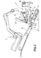
- the hopper 12 has a bottom part constituted by a grid 16, here made up of bars parallel arranged longitudinally and intended to retain excessively large cuttings, which can then be removed by lifting the hopper (see figure 2).
- the material passing through this grid falls on a vibrating screen 19, placed below the latter, then on a continuous conveyor 17, carried by the chassis 3 below of the vibrating screen and arranged transversely to the direction of movement thereof.
- This conveyor 17 projects laterally with respect to the chassis above the trench 14 and pours into it backfill materials.
- the conveyor 17 is driven by two reversible hydraulic motors carried by the chassis 3. As indicated above, it can also be moved transversely using a double-acting cylinder, in order to ability to project sideways on one side or the other from the chassis, so that the material can be filling both right and left of it.
- the various cylinders of the screening and backfill and the conveyor drive motors 17 and vibrating screen are fed and operated from a hydraulic cabinet 18 carried by the chassis 3. All of these organs are remotely controlled by a remote control placed in the excavator cabin or operated by an operator near the wiring device.
- the invention therefore provides a simple and inexpensive to backfill trenches, since the device used for backfilling is not self-propelled, but is towed by a hydraulic shovel, which has also for the function of supplying the backfilling with backfill material.
- the two ends of the chassis 3 are substantially identical, so that the screening device 2 integral in displacement of the hydraulic excavator 1 by one or other of these ends.
- the tracks of the screening and backfilling device can adapt to very uneven terrain and move forward for example on the cut bead 20 from trench 14 or on a runway 21 provided on the other side of this trench.
- the hydraulic excavator-screening and backfilling is suitable for climbing or descending slopes relatively sharp, up to 25 °.
Landscapes
- Engineering & Computer Science (AREA)
- Mining & Mineral Resources (AREA)
- Civil Engineering (AREA)
- General Engineering & Computer Science (AREA)
- Structural Engineering (AREA)
- Mechanical Engineering (AREA)
- Combined Means For Separation Of Solids (AREA)
- Investigation Of Foundation Soil And Reinforcement Of Foundation Soil By Compacting Or Drainage (AREA)
- Machines For Laying And Maintaining Railways (AREA)
Abstract
Description
La présente invention concerne un procédé de remblayage d'une tranchée et un dispositif pour la mise en oeuvre de ce procédé.The present invention relates to a backfill method a trench and a device for the implementation of this process.
On sait que, pour le transport de fluides sur de longues distances, de gaz, par exemple, ou de pétrole, on utilise des conduites du type des pipe-lines, qu'il est usuel de protéger en les enterrant dans des tranchées. Le remblayage de ces tranchées s'effectue habituellement en réutilisant les déblais de la tranchée, après criblage de ceux-ci, et l'on utilise généralement dans ce but un dispositif de criblage et de remblayage, qui est porté latéralement par un tracteur, qui se déplace le long de la tranchée.We know that for transporting fluids over long distances, gas, for example, or petroleum, we use pipes such as pipelines, which it is customary to protect by burying them in trenches. Backfilling of these trenches is usually done by reusing the cuttings from the trench, after screening them, and a device is generally used for this purpose screening and backfilling, which is carried laterally by a tractor, which moves along the trench.
Un dispositif de criblage et de remblayage de ce type comprend habituellement une trémie destinée à recevoir les matériaux utilisés pour le remblayage, un convoyeur continu disposé au-dessous de la trémie, et un système de tamis vibrants alimentés par le convoyeur continu et destinés à remplir la tranchée de couches successives de matériaux ayant une granulométrie déterminée. L'ensemble est solidaire d'un châssis, qui lui-même est supporté, en porte-à-faux au-dessus de la tranchée à remblayer, par un bras porteur d'un tracteur ou d'un dispositif analogue. On peut ainsi remblayer une tranchée, éventuellement en effectuant plusieurs passes avec un dispositif, avec différentes couches d'un même matériau ou de matériaux de granulométrie différentes.Such a screening and backfilling device usually includes a hopper to receive materials used for backfilling, a continuous conveyor arranged below the hopper, and a sieve system vibrators fed by the continuous conveyor and intended for fill the trench with successive layers of material having a determined particle size. The whole is united a frame, which itself is supported, cantilevered above of the trench to be backfilled, by an arm carrying a tractor or similar device. We can thus backfill a trench, possibly by carrying out multiple passes with one device, with different layers of the same material or of grain size materials different.
Un tel dispositif est décrit par exemple en détail dans le brevet U.S. N° 4 955 756, mais de nombreuses variantes existent sur le marché et la Demanderesse a elle-même proposé divers perfectionnements apportés à un dispositif de ce type, qui font l'objet de sa demande de brevet européen N° 0 709 526.Such a device is described for example in detail in U.S. Patent No. 4,955,756, but many variations exist on the market and the Applicant has itself proposed various improvements to a device this type, which are the subject of his European patent application No. 0 709 526.
Ces dispositifs donnent entière satisfaction, mais se révèlent relativement coûteux du fait qu'ils sont automoteurs.These devices are entirely satisfactory, but are are relatively expensive because they are self-propelled.
Le châssis présente, en outre, l'inconvénient d'être disposé en porte-à-faux par rapport au tracteur.The chassis also has the disadvantage of being cantilevered relative to the tractor.
Enfin, le remplissage de la trémie avec le matériau de remblayage doit être effectué à l'aide d'un engin indépendant du système de remblayage.Finally, the filling of the hopper with the material of backfilling must be carried out using a machine independent of the backfill system.
Pour remédier à ces inconvénients, l'invention propose d'utiliser non plus un système auto-moteur de remblayage, mais un système de criblage et de remblayage tracté par une pelle hydraulique d'un type conventionnel, qui assure en outre le chargement en matériau de remblayage du dispositif de criblage, l'ensemble pelle hydraulique-dispositif de criblage pouvant se déplacer aussi bien sur le cordon de déblais de la tranchée, que sur une piste disposée de l'autre côté de celle-ci.To remedy these drawbacks, the invention proposes no longer to use a self-powered backfill system, but a screening and backfilling system towed by a hydraulic excavator of a conventional type, which ensures in addition to loading the device with backfill material screening, the hydraulic excavator-device assembly screen can move as well on the cord cuttings from the trench, only on a track laid out the other side of it.
L'invention a par conséquent pour premier objet un procédé de remblayage d'une tranchée, notamment à l'aide des déblais provenant du creusement de cette tranchée, ce procédé consistant à tracter à l'aide d'une pelle hydraulique, parallèlement à la tranchée, un châssis monté sur roues ou sur chenilles, supportant une trémie de chargement équipée d'une grille à sa partie inférieure, à charger cette trémie en matériau de remblayage à l'aide de la pelle hydraulique, à transférer par gravité le matériau de remblayage à travers la grille sur un tamis vibrant disposé au-dessous de la trémie, puis sur un convoyeur continu, disposé au-dessous du tamis vibrant sur le châssis, transversalement à sa direction de déplacement, le tamis vibrant et le convoyeur étant entraínés par des moyens moteurs portés par le châssis, et à déverser le matériau de remplissage latéralement dans la tranchée à l'aide du convoyeur.The invention therefore has for first object a method of backfilling a trench, in particular using spoil from the digging of this trench, this process of towing with a shovel hydraulic, parallel to the trench, a chassis mounted on wheels or on tracks, supporting a hopper of load equipped with a grid at its lower part, load this hopper with backfill using the hydraulic shovel, to transfer the material by gravity backfill through the grid on a vibrating screen placed below the hopper, then on a conveyor continuous, placed below the vibrating screen on the chassis, transverse to its direction of movement, the sieve vibrating and the conveyor being driven by means motors carried by the chassis, and to pour the material out laterally filling in the trench using the conveyor.
L'invention a également pour objet un dispositif apte à être tracté, pour le criblage d'un matériau de remblayage et le déversement de celui-ci dans une tranchée, et destiné à être utilisé dans le procédé défini ci-dessus, ce dispositif étant caractérisé en ce qu'il comporte :
- un châssis monté sur roues ou sur chenilles et équipé d'un moins un organe de liaison avec une pelle hydraulique apte à le remorquer ;
- sur ce châssis, une trémie de chargement du matériau de remblayage équipée d'une grille à sa partie inférieure ;
- au-dessous de cette grille, un tamis vibrant ;
- au-dessous de ce tamis vibrant, un convoyeur continu dont une extrémité fait saillie latéralement par rapport au châssis ;
- et des moyens d'entraínement du tamis vibrant et du convoyeur portés par le châssis.
- a chassis mounted on wheels or on tracks and fitted with at least one connecting member with a hydraulic shovel capable of towing it;
- on this chassis, a hopper for loading the backfill material equipped with a grid at its lower part;
- below this grid, a vibrating screen;
- below this vibrating screen, a continuous conveyor, one end of which projects laterally with respect to the chassis;
- and means for driving the vibrating screen and the conveyor carried by the chassis.
L'organe de liaison avec la pelle hydraulique peut être un simple timon articulé à une extrémité sur le châssis et à son autre extrémité sur la pelle hydraulique.The link with the hydraulic excavator can be a simple drawbar articulated at one end on the chassis and its other end on the hydraulic shovel.
La trémie est de préférence montée pivotante par rapport au châssis, au moins un vérin étant prévu sur le châssis pour la redresser par pivotement par rapport à celui-ci, en vue d'évacuer les plus gros constituants du matériau de remblayage ne passant pas à travers la grille.The hopper is preferably pivotally mounted relative to to the chassis, at least one cylinder being provided on the chassis to straighten it by pivoting relative to it, in view of removing the largest constituents of the material backfill not passing through the grid.
Celle-ci peut être constituée de simples barreaux disposés en parallèle, par exemple parallèlement à la direction de déplacement du dispositif.This can be made up of simple bars arranged in parallel, for example parallel to the direction of movement of the device.
Quant au convoyeur, il est de préférence disposé transversalement à la direction de déplacement du châssis, sous la sollicitation de la pelle hydraulique dont il est rendu solidaire. Ce convoyeur est avantageusement mobile en translation sous la sollicitation d'un vérin à double effet, de manière à pouvoir faire saillie à volonté aussi bien du côté gauche que du côté droit du dispositif. Il est par ailleurs entraíné par au moins un moteur réversible, par exemple un moteur hydraulique, de manière à pouvoir déverser le matériau de remblayage à droite ou à gauche du dispositif.As for the conveyor, it is preferably arranged transversely to the direction of movement of the chassis, under the stress of the hydraulic shovel which it is made united. This conveyor is advantageously mobile in translation under the stress of a double-acting cylinder, so that it can protrude at will as well from left side than the right side of the device. He is by elsewhere driven by at least one reversible motor, by example a hydraulic motor, so that you can dump the backfill material to the right or left of the device.
L'invention a enfin pour objet un ensemble de remblayage d'une tranchée, caractérisé en ce qu'il comprend une pelle hydraulique et un dispositif de criblage et de déversement d'un matériau de remblayage du type qui vient d'être défini, ce dispositif étant solidaire en déplacement de la pelle hydraulique par un organe de liaison tel qu'un timon, de manière à pouvoir être tracté par la pelle.The invention finally relates to a backfill assembly a trench, characterized in that it comprises a shovel hydraulic and a screening and dumping device a backfill material of the type which has just been defined, this device being integral in displacement of the shovel hydraulic by a connecting member such as a drawbar, so that it can be towed by the shovel.
De préférence, le châssis du dispositif de criblage comprendra à chacune de ses extrémités de moyens permettant de le rendre solidaire en déplacement de la pelle hydraulique, afin qu'il puisse être tracté par l'une ou l'autre de ses extrémités.Preferably, the chassis of the screening device will include at each of its ends means allowing to make it integral in displacement of the shovel hydraulic, so that it can be towed by one or the other of its ends.
D'autres caractéristiques et avantages de l'invention apparaítront dans la description détaillée qui va suivre d'une forme de mise en oeuvre de celle-ci. Dans cette description, on se réfèrera aux dessins schématiques annexés, sur lesquels :Other characteristics and advantages of the invention will appear in the detailed description which follows of a form of implementation thereof. In this description, refer to schematic drawings annexed, on which:
La figure 1 est une vue en élévation latérale d'un
ensemble pelle hydraulique-dispositif de criblage et de
remblayage tracté par cette pelle, cet ensemble étant
représenté dans une position où la pelle descend une
pente ;
Sur ces dessins, la pelle hydraulique auto-motrice est
désignée par la référence 1, tandis que le dispositif de
criblage et de remblayage tracté par cette pelle est désigné
par la référence 2.In these drawings, the self-propelled hydraulic excavator is
designated by the
La pelle 1 peut être de tout type connu.The
Le dispositif 2 comporte un châssis 3, monté ici sur des
chenilles 4, mais qui pourrait aussi bien être porté par des
roues, sur lequel est articulé, par des leviers 5 et 6, un
timon 8 articulé à son autre extrémité sur le châssis de la
pelle 1.The
Le levier 6 est attaqué par la tige d'un vérin 7 porté par le châssis 3 du dispositif de criblage et de remblayage.The lever 6 is attacked by the rod of a jack 7 carried by the chassis 3 of the screening and backfilling device.
Ce châssis 3 est lié à la structure 9 portant les
chenilles 4 par un système de leviers tels que 10,
actionnables par un vérin 11, de manière à pouvoir maintenir
le châssis en position horizontale quelle que soit
l'inclinaison du terrain sur lequel prennent appui les
chenilles 4.This chassis 3 is linked to the
Une trémie 12, dont une extrémité contiguë à la pelle 1
est montée pivotante par rapport au châssis 3 sous la
sollicitation de vérins 13, reçoit de la pelle 1 les
matériaux bruts destinés au remblayage de la tranchée 14
(voir figure 4), par exemple en vue d'enfouir dans cette
tranchée un tube 15 qui y est logé.A
Les matériaux de remblayage sont le plus souvent
constitués par les déblais mêmes de la tranchée 4 et il
convient de les cribler avant le remblayage ce celle-ci.
Dans ce but, la trémie 12 comporte une partie de fond
constituée par une grille 16, ici constituée de barreaux
parallèles disposés longitudinalement et destinés à retenir
les déblais trop volumineux, que l'on peut ensuite évacuer
en soulevant la trémie (voir figure 2).Backfill materials are most often
formed by the same cuttings from trench 4 and it
should be screened before backfilling this one.
For this purpose, the
Le matériau passant au travers de cette grille tombe sur
un tamis vibrant 19, disposé au-dessous de celle-ci, puis
sur un convoyeur continu 17, porté par le châssis 3 au-dessous
du tamis vibrant et disposé transversalement à la
direction du déplacement de celui-ci.The material passing through this grid falls on
a vibrating
Ce convoyeur 17 fait saillie latéralement par rapport au
châssis au-dessus de la tranchée 14 et déverse dans celle-ci
les matériaux de remblai. Le convoyeur 17 est entraíné par
deux moteurs hydrauliques réversibles portés par le châssis
3. Comme indiqué ci-dessus, il peut en outre être déplacé
transversalement à l'aide d'un vérin double effet, afin de
pouvoir faire saillie latéralement d'un côté ou de l'autre
du châssis, de manière à pouvoir déverser le matériau de
remplissage aussi bien à droite qu'à gauche de celui-ci.This
Les divers vérins du dispositif de criblage et de
remblayage et les moteurs d'entraínement du convoyeur 17 et
du tamis vibrant sont alimentés et actionnés à partir d'une
armoire hydraulique 18 portée par le châssis 3. Tous ces
organes sont commandés à distance par une télécommande
placée dans la cabine de la pelle hydraulique ou actionnée
par un opérateur à proximité du dispositif de câblage.The various cylinders of the screening and
backfill and the
L'invention apporte, par conséquent, un moyen simple et peu coûteux pour remblayer des tranchées, puisque le dispositif utilisé pour le remblayage n'est pas automoteur, mais est remorqué par une pelle hydraulique, laquelle a également pour fonction d'alimenter le dispositif de remblayage en matériau de remblai.The invention therefore provides a simple and inexpensive to backfill trenches, since the device used for backfilling is not self-propelled, but is towed by a hydraulic shovel, which has also for the function of supplying the backfilling with backfill material.
On notera que les deux extrémités du châssis 3 sont
sensiblement identiques, de manière à pouvoir rendre le
dispositif du criblage 2 solidaire en déplacement de la
pelle hydraulique 1 par l'une ou l'autre de ces extrémités.It will be noted that the two ends of the chassis 3 are
substantially identical, so that the
Comme on le voit sur la figure 4, les chenilles du
dispositif de criblage et de remblayage peuvent s'adapter à
des terrains très inégaux et avancer par exemple sur le
cordon de déblai 20 de la tranchée 14 ou sur une piste 21
prévue de l'autre côté de cette tranchée.As seen in Figure 4, the tracks of the
screening and backfilling device can adapt to
very uneven terrain and move forward for example on the
Comme on le voit également sur les figures 1 et 2, l'ensemble pelle hydraulique-dispositif de criblage et de remblayage est apte à gravir ou à descendre des pentes relativement accusées, pouvant aller jusqu'à 25°.As can also be seen in Figures 1 and 2, the hydraulic excavator-screening and backfilling is suitable for climbing or descending slopes relatively sharp, up to 25 °.
Claims (8)
Applications Claiming Priority (2)
| Application Number | Priority Date | Filing Date | Title |
|---|---|---|---|
| FR9807770A FR2780079B1 (en) | 1998-06-19 | 1998-06-19 | METHOD AND DEVICE FOR BACKFILLING A TRENCH |
| FR9807770 | 1998-06-19 |
Publications (2)
| Publication Number | Publication Date |
|---|---|
| EP0965697A1 true EP0965697A1 (en) | 1999-12-22 |
| EP0965697B1 EP0965697B1 (en) | 2003-10-15 |
Family
ID=9527609
Family Applications (1)
| Application Number | Title | Priority Date | Filing Date |
|---|---|---|---|
| EP99401498A Expired - Lifetime EP0965697B1 (en) | 1998-06-19 | 1999-06-17 | Method and apparatus for filling trenches |
Country Status (7)
| Country | Link |
|---|---|
| EP (1) | EP0965697B1 (en) |
| AU (1) | AU747651B2 (en) |
| CA (1) | CA2275067A1 (en) |
| DE (1) | DE69912026T2 (en) |
| ES (1) | ES2209353T3 (en) |
| FR (1) | FR2780079B1 (en) |
| PT (1) | PT965697E (en) |
Cited By (4)
| Publication number | Priority date | Publication date | Assignee | Title |
|---|---|---|---|---|
| WO2004026478A2 (en) * | 2002-09-17 | 2004-04-01 | Rossi Jr Robert Richard | Mobile impact crusher assembly |
| GB2405394A (en) * | 2003-08-29 | 2005-03-02 | Kevin Gates | A material handling apparatus comprising a conveyor |
| US6871807B2 (en) | 2002-09-17 | 2005-03-29 | Robert R. Rossi, Jr. | Mobile impact crusher assembly |
| US6915972B2 (en) | 2002-09-17 | 2005-07-12 | Robert R. Rossi, Jr. | Mobile jaw crusher assembly |
Families Citing this family (5)
| Publication number | Priority date | Publication date | Assignee | Title |
|---|---|---|---|---|
| AU2003269608B2 (en) * | 2002-11-28 | 2007-08-02 | Mitchell Australasia Pty Ltd. | Trench forming and preparing apparatus |
| GB2412936B (en) * | 2002-11-28 | 2006-06-21 | Mitchell Australasia Pty Ltd | Trench forming and preparing apparatus |
| AU2002952972A0 (en) * | 2002-11-28 | 2002-12-12 | Mitchell Australasia Pty Ltd | Trench forming and preparing apparatus |
| DE102018201077B3 (en) | 2018-01-24 | 2019-05-16 | HGS Hirschfelder Greifer- und Stahlbau GmbH | Device for profile-controlled drilling and filling of pipe and cable trenches |
| CN114922242B (en) * | 2022-05-26 | 2024-06-21 | 利高实业(广州)有限公司 | Foundation landfill device for building construction |
Citations (7)
| Publication number | Priority date | Publication date | Assignee | Title |
|---|---|---|---|---|
| FR1347882A (en) * | 1962-11-23 | 1964-01-04 | Road construction method and device for its implementation | |
| US3701422A (en) * | 1970-05-21 | 1972-10-31 | Zurn Eng | Vehicle mounted earth separating and conveying system |
| US4322178A (en) * | 1980-02-29 | 1982-03-30 | Lee Billy R | Pavement patching apparatus |
| DE3510597A1 (en) * | 1985-03-23 | 1986-10-09 | Hannes-Jürgen 3000 Hannover Kapuschinski | Screening device for the loading of excavators and wheeled loaders |
| EP0334143A1 (en) * | 1988-03-23 | 1989-09-27 | KLEEMANN + REINER MASCHINEN- UND ANLAGENBAU VERTRIEBS GmbH | Apparatus for breaking materials, especially stone, and building and road building materials |
| EP0367207A1 (en) * | 1988-11-03 | 1990-05-09 | Hannes-Jürgen Kapuschinski | Screening device |
| WO1997041971A1 (en) * | 1996-05-03 | 1997-11-13 | Douglas Patrick J | Self-propelled material-processing apparatus |
Family Cites Families (2)
| Publication number | Priority date | Publication date | Assignee | Title |
|---|---|---|---|---|
| US4861461A (en) * | 1987-06-08 | 1989-08-29 | Utterback Eugene C | Pipeline padding machine and method |
| FR2726304B1 (en) * | 1994-10-31 | 1997-01-17 | Somico | IMPROVEMENTS IN FILLING DEVICES OF A TRENCH, IN PARTICULAR OF A TRENCH IN WHICH A FLUID CONVEYOR IS HOSTED |
-
1998
- 1998-06-19 FR FR9807770A patent/FR2780079B1/en not_active Expired - Fee Related
-
1999
- 1999-06-17 CA CA 2275067 patent/CA2275067A1/en not_active Abandoned
- 1999-06-17 DE DE69912026T patent/DE69912026T2/en not_active Expired - Lifetime
- 1999-06-17 ES ES99401498T patent/ES2209353T3/en not_active Expired - Lifetime
- 1999-06-17 PT PT99401498T patent/PT965697E/en unknown
- 1999-06-17 EP EP99401498A patent/EP0965697B1/en not_active Expired - Lifetime
- 1999-06-18 AU AU35745/99A patent/AU747651B2/en not_active Ceased
Patent Citations (7)
| Publication number | Priority date | Publication date | Assignee | Title |
|---|---|---|---|---|
| FR1347882A (en) * | 1962-11-23 | 1964-01-04 | Road construction method and device for its implementation | |
| US3701422A (en) * | 1970-05-21 | 1972-10-31 | Zurn Eng | Vehicle mounted earth separating and conveying system |
| US4322178A (en) * | 1980-02-29 | 1982-03-30 | Lee Billy R | Pavement patching apparatus |
| DE3510597A1 (en) * | 1985-03-23 | 1986-10-09 | Hannes-Jürgen 3000 Hannover Kapuschinski | Screening device for the loading of excavators and wheeled loaders |
| EP0334143A1 (en) * | 1988-03-23 | 1989-09-27 | KLEEMANN + REINER MASCHINEN- UND ANLAGENBAU VERTRIEBS GmbH | Apparatus for breaking materials, especially stone, and building and road building materials |
| EP0367207A1 (en) * | 1988-11-03 | 1990-05-09 | Hannes-Jürgen Kapuschinski | Screening device |
| WO1997041971A1 (en) * | 1996-05-03 | 1997-11-13 | Douglas Patrick J | Self-propelled material-processing apparatus |
Cited By (5)
| Publication number | Priority date | Publication date | Assignee | Title |
|---|---|---|---|---|
| WO2004026478A2 (en) * | 2002-09-17 | 2004-04-01 | Rossi Jr Robert Richard | Mobile impact crusher assembly |
| WO2004026478A3 (en) * | 2002-09-17 | 2004-11-18 | Jr Robert Richard Rossi | Mobile impact crusher assembly |
| US6871807B2 (en) | 2002-09-17 | 2005-03-29 | Robert R. Rossi, Jr. | Mobile impact crusher assembly |
| US6915972B2 (en) | 2002-09-17 | 2005-07-12 | Robert R. Rossi, Jr. | Mobile jaw crusher assembly |
| GB2405394A (en) * | 2003-08-29 | 2005-03-02 | Kevin Gates | A material handling apparatus comprising a conveyor |
Also Published As
| Publication number | Publication date |
|---|---|
| AU3574599A (en) | 2000-01-06 |
| EP0965697B1 (en) | 2003-10-15 |
| DE69912026D1 (en) | 2003-11-20 |
| DE69912026T2 (en) | 2004-07-15 |
| FR2780079B1 (en) | 2000-09-08 |
| PT965697E (en) | 2004-03-31 |
| AU747651B2 (en) | 2002-05-16 |
| CA2275067A1 (en) | 1999-12-19 |
| FR2780079A1 (en) | 1999-12-24 |
| ES2209353T3 (en) | 2004-06-16 |
Similar Documents
| Publication | Publication Date | Title |
|---|---|---|
| FR2566020A1 (en) | AUTONOMOUS CRUSHING STATION | |
| EP0965697B1 (en) | Method and apparatus for filling trenches | |
| EP2239377A1 (en) | Motorized machine for digging a trench in the soil and for depositing in said trench long objects | |
| FR2491992A1 (en) | CONTINUOUS SLAUGHTERING AND LOADING MACHINE FOR THE EXPLOITATION OF A SUBTERRANEAN MINE OF HARD ROCK METAL ORE | |
| HU223214B1 (en) | Method for padding ground below a dust using excavated soil, device for realising the same, equipment for compacting soil below a dust and soil-compacting mechanism | |
| EP0014154A1 (en) | Towed implement for picking up and transporting materials | |
| EP0524299B1 (en) | Device for picking up and storing grass or similar products and vehicles fitted with such device | |
| US2903803A (en) | Log handling apparatus | |
| US5864971A (en) | Debris removing apparatus | |
| FR2726304A1 (en) | IMPROVEMENTS IN THE DEVICES FOR FILLING A TRENCH, IN PARTICULAR A TRENCH IN WHICH A FLUID TRANSPORT CONDUIT IS LOCATED | |
| FR2722809A1 (en) | Trench digging, cable laying and backfilling machine | |
| FR2539157A1 (en) | ARROW SLICER | |
| EP0197833A1 (en) | Public works machine such as a scraper-loader | |
| JPH11155331A (en) | Harvester for peanut | |
| FR2695667A1 (en) | Trench-cutting machine for draining sports fields etc. - comprises digging tool and hopper for granulated drainage material. mounted on wheeled chassis, and box for rubble with two adjustable sole plates | |
| FR2714090A1 (en) | Scraper bucket for underground workings | |
| FR3121691A1 (en) | Trencher equipped with a digging device and an adjustable transverse belt. | |
| FR2542568A1 (en) | Mill/recoverer of forestry products | |
| FR2714920A1 (en) | Self-loading machine for filling in trenches after laying pipelines or cables | |
| AU707344B2 (en) | Debris removing apparatus | |
| BE854060A (en) | SELF-PROPELLED APPLIANCE FOR CLEANING BEET | |
| JPH0537015U (en) | Pick-up device for dual use | |
| FR2502889A1 (en) | Clipping-removing device for mower - has pneumatic hose connected to collection bag which is mounted on pivotal cradle on wheeled chassis | |
| FR2634347A1 (en) | FEEDING DEVICE FOR SEPARATING AND COLLECTING FEED | |
| CA2114483A1 (en) | Pipeline plow |
Legal Events
| Date | Code | Title | Description |
|---|---|---|---|
| PUAI | Public reference made under article 153(3) epc to a published international application that has entered the european phase |
Free format text: ORIGINAL CODE: 0009012 |
|
| AK | Designated contracting states |
Kind code of ref document: A1 Designated state(s): BE CH DE ES GB IT LI NL PT |
|
| AX | Request for extension of the european patent |
Free format text: AL;LT;LV;MK;RO;SI |
|
| 17P | Request for examination filed |
Effective date: 20000207 |
|
| AKX | Designation fees paid |
Free format text: BE CH DE ES GB IT LI NL PT |
|
| 17Q | First examination report despatched |
Effective date: 20021010 |
|
| GRAH | Despatch of communication of intention to grant a patent |
Free format text: ORIGINAL CODE: EPIDOS IGRA |
|
| GRAS | Grant fee paid |
Free format text: ORIGINAL CODE: EPIDOSNIGR3 |
|
| GRAA | (expected) grant |
Free format text: ORIGINAL CODE: 0009210 |
|
| AK | Designated contracting states |
Kind code of ref document: B1 Designated state(s): BE CH DE ES GB IT LI NL PT |
|
| REG | Reference to a national code |
Ref country code: GB Ref legal event code: FG4D Free format text: NOT ENGLISH Ref country code: CH Ref legal event code: EP |
|
| BECA | Be: change of holder's address |
Owner name: LOC. SPIGAROLO, I-43011 BUSSETO(IT) Effective date: 20031015 Owner name: LAURINI *LODOVICO & C. SNCD-929, F-60530 NEUILLY E Effective date: 20031015 Owner name: SOC. *MINIERE ET COMMERCIALE Effective date: 20031015 |
|
| REF | Corresponds to: |
Ref document number: 69912026 Country of ref document: DE Date of ref document: 20031120 Kind code of ref document: P |
|
| RAP2 | Party data changed (patent owner data changed or rights of a patent transferred) |
Owner name: LAURINI LODOVICO & C. SNC Owner name: SOCIETE MINIERE ET COMMERCIALE |
|
| GBT | Gb: translation of ep patent filed (gb section 77(6)(a)/1977) |
Effective date: 20040128 |
|
| NLT2 | Nl: modifications (of names), taken from the european patent patent bulletin |
Owner name: SOCIETE MINIERE ET COMMERCIALE EN LAURINI LODOVICO |
|
| REG | Reference to a national code |
Ref country code: PT Ref legal event code: SC4A Free format text: AVAILABILITY OF NATIONAL TRANSLATION Effective date: 20040113 |
|
| REG | Reference to a national code |
Ref country code: ES Ref legal event code: FG2A Ref document number: 2209353 Country of ref document: ES Kind code of ref document: T3 |
|
| PLBE | No opposition filed within time limit |
Free format text: ORIGINAL CODE: 0009261 |
|
| STAA | Information on the status of an ep patent application or granted ep patent |
Free format text: STATUS: NO OPPOSITION FILED WITHIN TIME LIMIT |
|
| 26N | No opposition filed |
Effective date: 20040716 |
|
| PGFP | Annual fee paid to national office [announced via postgrant information from national office to epo] |
Ref country code: CH Payment date: 20050623 Year of fee payment: 7 |
|
| PGFP | Annual fee paid to national office [announced via postgrant information from national office to epo] |
Ref country code: BE Payment date: 20050628 Year of fee payment: 7 |
|
| PG25 | Lapsed in a contracting state [announced via postgrant information from national office to epo] |
Ref country code: LI Free format text: LAPSE BECAUSE OF NON-PAYMENT OF DUE FEES Effective date: 20060630 Ref country code: CH Free format text: LAPSE BECAUSE OF NON-PAYMENT OF DUE FEES Effective date: 20060630 Ref country code: BE Free format text: LAPSE BECAUSE OF NON-PAYMENT OF DUE FEES Effective date: 20060630 |
|
| REG | Reference to a national code |
Ref country code: CH Ref legal event code: PL |
|
| BERE | Be: lapsed |
Owner name: LAURINI *LODOVICO & C. SNC Effective date: 20060630 Owner name: SOC. *MINIERE ET COMMERCIALE Effective date: 20060630 |
|
| PGFP | Annual fee paid to national office [announced via postgrant information from national office to epo] |
Ref country code: ES Payment date: 20110624 Year of fee payment: 13 Ref country code: PT Payment date: 20110615 Year of fee payment: 13 |
|
| PGFP | Annual fee paid to national office [announced via postgrant information from national office to epo] |
Ref country code: GB Payment date: 20110620 Year of fee payment: 13 Ref country code: NL Payment date: 20110621 Year of fee payment: 13 |
|
| PGFP | Annual fee paid to national office [announced via postgrant information from national office to epo] |
Ref country code: DE Payment date: 20110622 Year of fee payment: 13 |
|
| PGFP | Annual fee paid to national office [announced via postgrant information from national office to epo] |
Ref country code: IT Payment date: 20110624 Year of fee payment: 13 |
|
| REG | Reference to a national code |
Ref country code: PT Ref legal event code: MM4A Free format text: LAPSE DUE TO NON-PAYMENT OF FEES Effective date: 20121217 |
|
| REG | Reference to a national code |
Ref country code: NL Ref legal event code: V1 Effective date: 20130101 |
|
| GBPC | Gb: european patent ceased through non-payment of renewal fee |
Effective date: 20120617 |
|
| PG25 | Lapsed in a contracting state [announced via postgrant information from national office to epo] |
Ref country code: PT Free format text: LAPSE BECAUSE OF NON-PAYMENT OF DUE FEES Effective date: 20121217 Ref country code: IT Free format text: LAPSE BECAUSE OF NON-PAYMENT OF DUE FEES Effective date: 20120617 |
|
| REG | Reference to a national code |
Ref country code: DE Ref legal event code: R119 Ref document number: 69912026 Country of ref document: DE Effective date: 20130101 |
|
| PG25 | Lapsed in a contracting state [announced via postgrant information from national office to epo] |
Ref country code: GB Free format text: LAPSE BECAUSE OF NON-PAYMENT OF DUE FEES Effective date: 20120617 Ref country code: DE Free format text: LAPSE BECAUSE OF NON-PAYMENT OF DUE FEES Effective date: 20130101 Ref country code: NL Free format text: LAPSE BECAUSE OF NON-PAYMENT OF DUE FEES Effective date: 20130101 |
|
| REG | Reference to a national code |
Ref country code: ES Ref legal event code: FD2A Effective date: 20131022 |
|
| PG25 | Lapsed in a contracting state [announced via postgrant information from national office to epo] |
Ref country code: ES Free format text: LAPSE BECAUSE OF NON-PAYMENT OF DUE FEES Effective date: 20120618 |