EP0965016B1 - Device for cleaning and lubricating drive chains - Google Patents
Device for cleaning and lubricating drive chains Download PDFInfo
- Publication number
- EP0965016B1 EP0965016B1 EP98906740A EP98906740A EP0965016B1 EP 0965016 B1 EP0965016 B1 EP 0965016B1 EP 98906740 A EP98906740 A EP 98906740A EP 98906740 A EP98906740 A EP 98906740A EP 0965016 B1 EP0965016 B1 EP 0965016B1
- Authority
- EP
- European Patent Office
- Prior art keywords
- housing
- cleaning
- drive chain
- brushes
- nozzles
- Prior art date
- Legal status (The legal status is an assumption and is not a legal conclusion. Google has not performed a legal analysis and makes no representation as to the accuracy of the status listed.)
- Expired - Lifetime
Links
Images


Classifications
-
- F—MECHANICAL ENGINEERING; LIGHTING; HEATING; WEAPONS; BLASTING
- F16—ENGINEERING ELEMENTS AND UNITS; GENERAL MEASURES FOR PRODUCING AND MAINTAINING EFFECTIVE FUNCTIONING OF MACHINES OR INSTALLATIONS; THERMAL INSULATION IN GENERAL
- F16H—GEARING
- F16H57/00—General details of gearing
- F16H57/04—Features relating to lubrication or cooling or heating
- F16H57/05—Features relating to lubrication or cooling or heating of chains
-
- B—PERFORMING OPERATIONS; TRANSPORTING
- B62—LAND VEHICLES FOR TRAVELLING OTHERWISE THAN ON RAILS
- B62J—CYCLE SADDLES OR SEATS; AUXILIARY DEVICES OR ACCESSORIES SPECIALLY ADAPTED TO CYCLES AND NOT OTHERWISE PROVIDED FOR, e.g. ARTICLE CARRIERS OR CYCLE PROTECTORS
- B62J31/00—Installations of lubricating devices
-
- F—MECHANICAL ENGINEERING; LIGHTING; HEATING; WEAPONS; BLASTING
- F16—ENGINEERING ELEMENTS AND UNITS; GENERAL MEASURES FOR PRODUCING AND MAINTAINING EFFECTIVE FUNCTIONING OF MACHINES OR INSTALLATIONS; THERMAL INSULATION IN GENERAL
- F16N—LUBRICATING
- F16N7/00—Arrangements for supplying oil or unspecified lubricant from a stationary reservoir or the equivalent in or on the machine or member to be lubricated
-
- F—MECHANICAL ENGINEERING; LIGHTING; HEATING; WEAPONS; BLASTING
- F16—ENGINEERING ELEMENTS AND UNITS; GENERAL MEASURES FOR PRODUCING AND MAINTAINING EFFECTIVE FUNCTIONING OF MACHINES OR INSTALLATIONS; THERMAL INSULATION IN GENERAL
- F16N—LUBRICATING
- F16N2210/00—Applications
- F16N2210/33—Chains
Definitions
- the present invention relates to a device for cleaning and lubricating of drive chains according to the preamble of claim 1.
- DE-A 38 39 076 describes a device for cleaning and drying Known chains for road bikes, which has a two-part housing, through which the Chain is passed through. Bristle wheels are arranged in the housing mechanically clean the chain on the one hand and in the lower area on the other deflect the housing. In this lower area of the housing is one Trough designed that can hold a cleaning medium. The chain will cleaned by immersing in this cleaning medium. Redirecting the Depending on the chain tension, chain requires a relatively large force from the device must be included. Furthermore, this known solution disadvantageous that the dirt detached from the chain accumulates in the tub and partially get back on the chain the inside of the chain, its cleaning and lubrication are particularly critical is disadvantaged in this procedure.
- GB-A 20 597 is a device for cleaning and lubricating disclosed by bicycle chains.
- the chain to be cleaned is attached to a wheel passed by, which dips into a tub that contains a lubricant is. By turning this wheel, the lubricant is applied to the Chain applied.
- the cleaning effect of such a device is extremely limited, since only very coarse dirt adhering to the chain is stripped off can be.
- EP-A 0 599 087 describes a device for lubrication and cleaning known by chains and rails. There are several shoe-like modules in a row switched, which surround the chain to be cleaned on three sides and which have brushes and cleaning nozzles. Because this system is down is open, use can only take place in a workshop or the like in which the considerable pollution of the environment is tolerable. A similar The device is described in WO 86/05153.
- US 5 360 084 A describes a cleaning and lubricating device for Drive chains that enclose the drive chain on both sides and above. This device is open at the bottom. Hence the excess flow Cleaning agents and lubricants uncontrolled down what the causes problems described above.
- the object of the present invention is a device of the type described above Kind in such a way that a reliable and effective cleaning of Drive chains are possible and that this cleaning largely with little effort can be carried out without polluting the environment.
- the cleaning in one way closed housing takes place, with the cleaning medium only once the chain comes into contact and is then collected and pulled off.
- the Application takes place through nozzles which are directed onto the drive chain, to increase the effectiveness of cleaning.
- the above applies in analog Way also for a lubricant that is applied after cleaning the drive chain can be. It is particularly important here that no lubricant can escape from the device into the environment in an uncontrolled manner. Hence the Device according to the invention can also be used wherever any environmental pollution is not permitted.
- the upstream brushes have the task of a mechanical one Pre-cleaning while the downstream brushes are another one Wipe off the loosened by the cleaning medium, but under Under certain circumstances, not yet fully removed dirt particles and on the other hand, the adhering cleaning medium or excess lubricant strip.
- a particularly simple construction of the device is achieved in that the housing holding elements are arranged, which have both nozzles also wear brushes.
- FIG. 1 the rear wheel 1 of a motorcycle is shown schematically.
- the Rear wheel 1 is driven by a drive chain 2, which is known per se Way is wound around a sprocket 3.
- a drive chain 2 which is known per se Way is wound around a sprocket 3.
- Device 4 arranged with a schematically shown Retaining bracket 5 is attached to a fixed structural part of the motorcycle.
- the drive chain 2 in the Moves in the direction of arrow 6a, so that the rear wheel 1 moves in the direction of the Arrow 6b rotates.
- the motorcycle is during the cleaning or lubrication process jacked up or placed on the main stand so that the rotation of the Rear wheel 1 is not disabled.
- FIG. 2 shows the basic structure of the device according to the invention seen.
- the housing halves 7, 8 of the device 4 according to the invention are in of Fig. 2 indicated by broken lines. Inside the housing halves 7, 8 are arranged brushes 9, the drive chain 2 from different directions strip. Nozzles are schematically indicated at 10 to a cleaning agent or spray lubricant on the chain in the direction of arrows 11. The cleaning agent or lubricant becomes the nozzles via holes 12 10 led. Rubber lips 13 are arranged at the passage points of the chain 2, to also seal the device in these areas.
- the lower half of the case 8 is funnel-shaped in the lower region 14 and with a Drain opening 15 provided.
- the brushes 9 and nozzles 10 are each common in holding elements 18 arranged which are substantially transverse to the axial direction of the Extend device.
- the bores 12 in the holding elements 18 are also available Connections 19 in connection, on which hoses can be attached, in order to introduce a cleaning agent or lubricant into the interior of the device 4.
- a simple spray bottle can be used, for example, however, it can also do the corresponding via a spray gun with compressed air Medium are fed.
- the brushes 9 are on both sides of the nozzles 10 arranged to remove any excess cleaning or lubricant from the To strip the chain.
- FIG. 5 it can be seen that in the lateral areas of the device Flanges 20, 21 are provided, which are provided with bores 22.
- the holes 22 are used for hanging a wire bracket or the like.
- FIG. 1 is shown schematically at 5. This ensures that even when moving the drive chain 2, the device 4 remains in the intended place.
- the present invention enables the drive chain 2 of a motorcycle in effective cleaning and lubrication. Through the special training the device can virtually completely contaminate the environment be prevented. Furthermore, the consumption of cleaning and Lubricants are very low compared to alternative solutions.
- the invention The device is particularly easy and simple to use and user-friendly.
Abstract
Description
Die vorliegende Erfindung betrifft eine Vorrichtung zum Reinigen und Schmieren
von Antriebsketten gemäß dem Oberbegriff von Patentanspruch 1.The present invention relates to a device for cleaning and lubricating
of drive chains according to the preamble of
Die Lebensdauer der Antriebsketten von Motorrädern, Landmaschinen und dgl. hängt wesentlich von der Pflege und Reinigung während des Betriebs ab. Kleine Fremdkörper, wie etwa Sand od. dgl., die sich an den Gelenken der Antriebskette festsetzen, verringern die Lebensdauer beträchtlich. Daher ist eine regelmäßige Pflege und Reinigung der Antriebsketten wichtig. Mit bisher bekannten Vorrichtungen ist jedoch der Reinigungsvorgang mühsam und im allgemeinen mit einer großen Verschmutzung der Umgebung und der benachbarten Bauteile verbunden.The lifespan of the drive chains of motorcycles, agricultural machinery and the like. depends essentially on the care and cleaning during operation. little one Foreign objects, such as sand or the like, which are located on the joints of the drive chain fix, reduce the lifespan considerably. Therefore, it is regular Care and cleaning of the drive chains important. With previously known devices however, the cleaning process is tedious and generally with one large pollution of the environment and the neighboring components.
Aus der DE-A 38 39 076 ist eine Einrichtung zum Säubern und Trocknen von Ketten für Rennräder bekannt, die ein zweiteiliges Gehäuse besitzt, durch das die Kette hindurchgeführt wird. In dem Gehäuse sind Borstenräder angeordnet, die die Kette einerseits mechanisch reinigen und andererseits in den unteren Bereich des Gehäuses umlenken. In diesem unteren Bereich des Gehäuses ist eine Wanne ausgebildet, die ein Reinigungsmedium aufnehmen kann. Die Kette wird durch das Eintauchen in dieses Reinigungsmedium gesäubert. Das Umlenken der Kette erfordert je nach Kettenspannung eine relativ große Kraft, die von der Einrichtung aufgenommen werden muss. Weiters ist bei dieser bekannten Lösung nachteilig, dass sich der von der Kette abgelöste Schmutz in der Wanne ansammelt und teilweise wieder zurück auf die Kette gelangen kann.. Weiters wird gerade die Innenseite der Kette, deren Reinigung und Schmierung besonders kritisch ist, bei diesem Verfahren benachteiligt.DE-A 38 39 076 describes a device for cleaning and drying Known chains for road bikes, which has a two-part housing, through which the Chain is passed through. Bristle wheels are arranged in the housing mechanically clean the chain on the one hand and in the lower area on the other deflect the housing. In this lower area of the housing is one Trough designed that can hold a cleaning medium. The chain will cleaned by immersing in this cleaning medium. Redirecting the Depending on the chain tension, chain requires a relatively large force from the device must be included. Furthermore, this known solution disadvantageous that the dirt detached from the chain accumulates in the tub and partially get back on the chain the inside of the chain, its cleaning and lubrication are particularly critical is disadvantaged in this procedure.
Weiters ist In der GB-A 20 597 eine Vorrichtung zum Reinigen und Schmieren
von Fahrradketten offenbart. Die zu reinigende Kette wird dabei an einem Rädchen
vorbeigeführt, das in eine Wanne eintaucht, in der ein Schmiermittel enthalten
ist. Durch die Drehung dieses Rädchens wird das Schmiermittel auf die
Kette aufgetragen. Die Reinigungswirkung einer solchen Vorrichtung ist jedoch
äußerst beschränkt, da nur sehr grober Schmutz, der an der Kette anhaftet-, abgestreift
werden kann. Furthermore, GB-
Ferner ist aus der EP-A 0 599 087 eine Vorrichtung zum Schmieren und Reinigen von Ketten und Schienen bekannt. Dabei sind mehrere schuhartige Module hintereinander geschaltet, die die zu reinigende Kette an drei Seiten umgeben und die Bürsten und Reinigungsdüsen aufweisen. Da dieses System nach unten hin offen ist, kann eine Verwendung nur in einer Werkstatt od. dgl. erfolgen, in der die erhebliche Schmutzbelastung der Umgebung tolerierbar ist. Eine ähnliche Vorrichtung ist in der WO 86/05153 beschrieben.Furthermore, EP-A 0 599 087 describes a device for lubrication and cleaning known by chains and rails. There are several shoe-like modules in a row switched, which surround the chain to be cleaned on three sides and which have brushes and cleaning nozzles. Because this system is down is open, use can only take place in a workshop or the like in which the considerable pollution of the environment is tolerable. A similar The device is described in WO 86/05153.
Die US 5 360 084 A beschreibt eine Reinigungs- und Schmiereinrichtung für
Antriebsketten, die die Antriebskette an ihren beiden Seiten und oben umschließt.
An der Unterseite ist diese Vorrichtung offen. Daher rinnen die überschüssigen
Reinigungs- und Schmiermittel unkontrolliert nach unten ab, was die
oben beschriebenen Probleme verursacht.
Aufgabe der vorliegenden Erfindung ist es, eine Vorrichtung der oben beschriebenen Art so weiterzubilden, dass eine zuverlässige und wirksame Reinigung von Antriebsketten möglich ist und dass diese Reinigung mit geringem Aufwand weitgehend ohne Schmutzbelastung der Umgebung durchführbar ist.The object of the present invention is a device of the type described above Kind in such a way that a reliable and effective cleaning of Drive chains are possible and that this cleaning largely with little effort can be carried out without polluting the environment.
Die obige Aufgabe wird durch eine Ausbildung erreicht, die die Merkmale des
kennzeichnenden Teils von Patentanspruch 1 aufweist.The above task is accomplished through training that has the characteristics of
characterizing part of
Wesentlich an der vorliegenden Erfindung ist, dass die Reinigung in einem allseits geschlossenen Gehäuse stattfindet, wobei das Reinigungsmedium nur einmal mit der Kette in Kontakt kommt und darnach gesammelt und abgezogen wird. Das Aufbringen erfolgt dabei durch Düsen, die auf die Antriebskette gerichtet sind, um die Wirksamkeit der Reinigung zu steigern. Das oben Gesagte gilt In analoger Weise auch für ein Schmiermittel, das nach der Reinigung der Antriebskette aufgebracht werden kann. Hier ist es besonders wesentlich, dass kein Schmiermittel unkontrolliert aus der Vorrichtung in die Umgebung austreten kann. Daher ist die erfindungsgemäße Vorrichtung auch dort verwendbar, wo jegliche Umweltbelastung unzulässig ist.It is essential to the present invention that the cleaning in one way closed housing takes place, with the cleaning medium only once the chain comes into contact and is then collected and pulled off. The Application takes place through nozzles which are directed onto the drive chain, to increase the effectiveness of cleaning. The above applies in analog Way also for a lubricant that is applied after cleaning the drive chain can be. It is particularly important here that no lubricant can escape from the device into the environment in an uncontrolled manner. Hence the Device according to the invention can also be used wherever any environmental pollution is not permitted.
Bevorzugte Ausführungsvarianten der Erfindung sind in den Unteransprüchen angegeben. Durch die Abdichtung der Eintritts- und Austrittsstellen der Antriebskette durch Gummilippen od. dgl. kann sichergestellt werden, dass auch bei unterschiedlichen Dimensionen von Antriebsketten an diesen Stellen keine Leckage auftritt.Preferred embodiments of the invention are in the subclaims specified. By sealing the entry and exit points of the drive chain rubber lips or the like can ensure that even with different Dimensions of drive chains at these points no leakage occurs.
Besonders günstig ist es, wenn die Düsen an beiden Seiten von Bürsten umgeben sind. Die stromaufwärtigen Bürsten haben dabei die Aufgabe einer mechanischen Vorreinigung, während die stromabwärtigen Bürsten einerseits ein weiteres Abstreifen der durch das Reinigungsmedium zwar gelockerten, aber unter Umständen noch nicht vollständig entfernten Schmutzpartikel ermöglichen und andererseits das anhaftende Reinigungsmedium oder überschüssiges Schmiermittel abstreifen.It is particularly favorable if the nozzles are surrounded by brushes on both sides are. The upstream brushes have the task of a mechanical one Pre-cleaning while the downstream brushes are another one Wipe off the loosened by the cleaning medium, but under Under certain circumstances, not yet fully removed dirt particles and on the other hand, the adhering cleaning medium or excess lubricant strip.
Ein besonders einfacher Aufbau der Vorrichtung wird dadurch erreicht, dass in dem Gehäuse Halteelemente angeordnet sind, die sowohl Düsen aufweisen als auch Bürsten tragen.A particularly simple construction of the device is achieved in that the housing holding elements are arranged, which have both nozzles also wear brushes.
In der Folge wird die vorliegende Erfindung anhand der In den Figuren dargestellten Ausführungsbeispiele näher erläutert. Es zeigen:
- Fig.1
- einen Teil einer Antriebskette eines Motorrades mit der erfindungsgemäßen Vorrichtung,
- Fig. 2
- einen schematischen Schnitt durch die Vorrichtung,
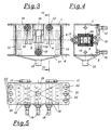
- Fig. 3
- eine seitliche Ansicht einer weiteren Ausführungsvariante der Erfindung,
- Fig. 4
- einen Schnitt nach der Linie IV-IV in Fig. 3,
- Fig. 5
- eine Ansicht der unteren Gehäusehälfte von oben,
- Fig. 6
- eine weitere Ausführungsvariante der Erfindung in einem Schnitt nach der Linie VI-VI in Fig. 7 und die
- Fig. 7
- einen Schnitt nach der Linie VII-VII in Fig. 6.
- Fig.1
- part of a drive chain of a motorcycle with the device according to the invention,
- Fig. 2
- a schematic section through the device,
- Fig. 3
- a side view of a further embodiment of the invention,
- Fig. 4
- a section along the line IV-IV in Fig. 3,
- Fig. 5
- a view of the lower half of the housing from above,
- Fig. 6
- a further embodiment of the invention in a section along the line VI-VI in Fig. 7 and the
- Fig. 7
- a section along the line VII-VII in Fig. 6.
In der Fig. 1 ist das Hinterrad 1 eines Motorrades schematisch dargestellt. Das
Hinterrad 1 wird über eine Antriebskette 2 angetrieben, die in an sich bekannter
Weise um ein Kettenrad 3 geschlungen ist. Am unteren Kettentrum ist die erfindungsgemäße
Vorrichtung 4 angeordnet, die mit einem schematisch dargestellten
Haltebügel 5 an einem festen Konstruktionsteil des Motorrades befestigt ist.
Während des Reinigungs- und Schmiervorganges wird die Antriebskette 2 in der
Richtung des Pfeils 6a bewegt, so dass sich das Hinterrad 1 in der Richtung des
Pfeils 6b dreht. Das Motorrad wird während des Reinigungs- oder Schmiervorganges
aufgebockt oder am Hauptständer aufgestellt, so dass die Drehung des
Hinterrades 1 nicht behindert ist.In Fig. 1, the
Aus der Fig. 2 ist der grundsätzliche Aufbau der erfindungsgemäßen Vorrichtung
ersichtlich. Die Gehäusehälften 7, 8 der erfindungsgemäßen Vorrichtung 4 sind in
der Fig. 2 mit unterbrochenen Linien angedeutet. Im Inneren der Gehäusehälften
7, 8 sind Bürsten 9 angeordnet, die die Antriebskette 2 aus verschiedenen Richtungen
abstreifen. Düsen sind schematisch mit 10 angedeutet, um ein Reinigungsmittel
oder Schmiermittel in Richtung der Pfeile 11 auf die Kette zu sprühen.
Das Reinigungs- oder Schmiermittel wird über Bohrungen 12 zu den Düsen
10 geführt. An den Durchtrittsstellen der Kette 2 sind Gummilippen 13 angeordnet,
um die Vorrichtung auch In diesen Bereichen abzudichten. Die untere Gehäusehälfte
8 ist im unteren Bereich 14 trichterförmig ausgebildet und mit einer
Abflussöffnung 15 versehen.2 shows the basic structure of the device according to the invention
seen. The
Aus der Darstellung der Fig. 3 ist ersichtlich, dass die beiden Gehäusehälften 7
und 8 durch einen Schnappverschluss 16 miteinander verbunden sind. Wie In der
Fig. 4 dargestellt ist, sind an der gegenüberliegenden Seite des Schnappverschlusses
16 Scharniere 17 angebracht, um die Gehäusehälften 7, 8 auseinander
klappen zu können. Die Bürsten 9 und Düsen 10 sind jeweils gemeinsam In Halteelementen
18 angeordnet, die sich im wesentlichen quer zur Axialrichtung der
Vorrichtung erstrecken. Die Bohrungen 12 in den Halteelementen 18 stehen mit
Anschlussstücken 19 in Verbindung, auf die Schläuche aufgesteckt werden können,
um ein Reinigungs- oder Schmiermittel in das Innere der Vorrichtung 4 einzubringen.
Dabei kann beispielsweise eine einfache Sprühflasche verwendet werden,
es kann jedoch auch über eine Spritzpistole mit Druckluft das entsprechende
Medium zugeführt werden. Die Bürsten 9 sind beidseits der Düsen 10
angeordnet, um jeweils überschüssiges Reinigungs- oder Schmiermittel von der
Kette abzustreifen.It can be seen from the illustration in FIG. 3 that the two
Aus der Fig. 4 ist der genaue Aufbau der Gummilippen 13 ersichtlich. Von jeder
der Seiten einer rechteckigen Ausnehmung 20 In den Gehäusehälften 7 und 8
ragt ein Blatt der Gummilippe 13 vor. Die Abmessungen der Gummilippen 13
sind dabei so gewählt, dass die verbleibende Öffnung kleiner als der Querschnitt
der Antriebskette ist.The exact structure of the
Aus der Fig. 5 ist ersichtlich, dass in den seitlichen Bereichen der Vorrichtung
Flansche 20, 21 vorgesehen sind, die mit Bohrungen 22 versehen sind. Die Bohrungen
22 dienen zum Einhängen eines Drahtbügels od. dgl., der in der Fig. 1
schematisch mit 5 dargestellt ist. Damit wird sichergestellt, dass auch bei Bewegung
der Antriebskette 2 die Vorrichtung 4 an dem vorgesehenen Platz verbleibt.From Fig. 5 it can be seen that in the lateral areas of the
In den Fig. 6 und 7 ist eine geringfügig abgeänderte Ausführungsvariante der
Erfindung detailliert dargestellt. Die entsprechenden Bauteile sind mit den gleichen
Bezugszeichen bezeichnet, wie bei der oben beschriebenen Ausführungsvariante
und eine detaillierte Beschreibung ist weggelassen. Bei dieser Ausführungsvariante
sind die Bürsten 9 im mittleren Bereich kürzer ausgeführt als Im
seitlichen Bereich. In jedem Halteelement 18 sind drei Düsen 10 angeordnet, um
eine optimale Verteilung des Reinigungs- oder Schmiermittels zu gewährleisten.
Welters ist aus der Fig. 7 ersichtlich, dass die Gummilippen 13 über Verschraubungen
23 mit den Halteelementen 18 der äußersten Bürsten 9a bzw. 9b verschraubt
sind. Diese Bürsten 9a und 9b sind dichter ausgeführt als die mittleren
Bürsten 9, um eine zusätzliche Abdichtungswirkung gegenüber den Öffnungen 24
für den Durchtritt der Antriebskette zu gewährleisten.6 and 7 is a slightly modified embodiment of the
Invention presented in detail. The corresponding components are the same
Reference numerals designate, as in the embodiment variant described above
and a detailed description is omitted. In this variant
the
Die vorliegende Erfindung ermöglicht es, die Antriebskette 2 eines Motorrades in
wirksamer Weise zu reinigen und zu schmieren. Durch die besondere Ausbildung
der Vorrichtung kann eine Verschmutzung der Umgebung dabei praktisch vollständig
verhindert werden. Weiters ist der Verbrauch an Reinigungs- und
Schmiermitteln im Vergleich zu alternativen Lösungen sehr gering. Die erfindungsgemäße
Vorrichtung ist dabei besonders leicht und einfach anwendbar und
benutzerfreundlich.The present invention enables the
Claims (6)
- An apparatus for cleaning and lubricating drive chains (2), in particular of motorcycles, with a housing enclosing the drive chain (2) on all sides and consisting of two mutually connectable halves (7, 8) and comprising openings for allowing the drive chain (2) to pass through provided with brushes (9) which are attached in the housing to wipe off the drive chain (2) and with inwardly facing nozzles (10) which are in connection with connections (19) on the outside of the housing, characterized in that the housing comprises a funnel-shaped zone with a drainage opening (15) which is arranged for bleeding off the media injected into the apparatus.
- An apparatus according to claim 1, characterized in that the openings of the housing for passing through the drive chain (2) are closed by rubber lips (13).
- An apparatus according to one of the claims 1 or 2, characterized in that the nozzles (10) are encompassed by brushes (9) on either side in the direction of movement of the drive chain (2).
- An apparatus according to one of the claims 1 to 3, characterized in that the housing consists of an upper and a lower half (7, 8) of the housing and that brushes (9) are attached on both halves (7, 8) of the housing.
- An apparatus according to one of the claims 1 to 4, characterized in that nozzles (10) are directed both against the upper side as well as the lower side of the drive chain (2).
- An apparatus according to one of the claims 1 to 5, characterized in that fixing elements (18) are arranged which are both provided with nozzles (10) as well as hold brushes (9).
Priority Applications (1)
| Application Number | Priority Date | Filing Date | Title |
|---|---|---|---|
| SI9830298T SI0965016T1 (en) | 1997-03-07 | 1998-03-05 | Device for cleaning and lubricating drive chains |
Applications Claiming Priority (3)
| Application Number | Priority Date | Filing Date | Title |
|---|---|---|---|
| AT38697 | 1997-03-07 | ||
| AT0038697A AT406141B (en) | 1997-03-07 | 1997-03-07 | DEVICE FOR CLEANING AND LUBRICATING DRIVE CHAINS, ESPECIALLY MOTORCYCLES |
| PCT/AT1998/000053 WO1998040662A1 (en) | 1997-03-07 | 1998-03-05 | Device for cleaning and lubricating drive chains |
Publications (2)
| Publication Number | Publication Date |
|---|---|
| EP0965016A1 EP0965016A1 (en) | 1999-12-22 |
| EP0965016B1 true EP0965016B1 (en) | 2002-09-25 |
Family
ID=3489222
Family Applications (1)
| Application Number | Title | Priority Date | Filing Date |
|---|---|---|---|
| EP98906740A Expired - Lifetime EP0965016B1 (en) | 1997-03-07 | 1998-03-05 | Device for cleaning and lubricating drive chains |
Country Status (9)
| Country | Link |
|---|---|
| US (1) | US6257369B1 (en) |
| EP (1) | EP0965016B1 (en) |
| JP (1) | JP3328782B2 (en) |
| AT (2) | AT406141B (en) |
| AU (1) | AU732253B2 (en) |
| CA (1) | CA2283140C (en) |
| DE (1) | DE59805695D1 (en) |
| ES (1) | ES2183330T3 (en) |
| WO (1) | WO1998040662A1 (en) |
Families Citing this family (33)
| Publication number | Priority date | Publication date | Assignee | Title |
|---|---|---|---|---|
| US6446756B1 (en) * | 2000-04-25 | 2002-09-10 | J. Ray Mcdermott, S.A. | Wire rope lubrication device for a crane |
| ITMI20071064A1 (en) * | 2007-05-25 | 2008-11-26 | Giorgio Passoni | DEVICE FOR CLEANING A MOTORCYCLE TRANSMISSION CHAIN |
| GB2456010B (en) * | 2007-12-29 | 2010-05-19 | Ming-Chi Yu | A brush assembly for cleaning motorcycle chain |
| US20090165229A1 (en) * | 2007-12-31 | 2009-07-02 | Ming-Chi Yu | Brush assembly for cleaning motorcycle chain |
| US20090223745A1 (en) * | 2008-03-04 | 2009-09-10 | Marcucci Peter J | Chain lubrication tool |
| US8181747B2 (en) | 2008-10-29 | 2012-05-22 | Crestron Electronics Inc. | Bicycle chain cleaner and lubrication apparatus |
| ITPG20090048A1 (en) * | 2009-10-02 | 2011-04-03 | Giampiero Sensi | PORTABLE WASHING MACHINE FOR WASHING: MOORING WHEELS, DRIZERS, SHEETS, ANCHOR CHAIN ETC. OF A BOAT WITHOUT THE NEED FOR THEIR REMOVAL. |
| EP2311720A1 (en) * | 2009-10-15 | 2011-04-20 | Sonny Petersen | A vehicle sprocket chain maintenance apparatus and method. |
| US9079720B1 (en) * | 2010-07-02 | 2015-07-14 | Linear Market Technical Services Corporation | Roller chain lubricator |
| US20160138703A1 (en) * | 2011-08-02 | 2016-05-19 | Patrick R. Doran | Tool for the Application and Dispensing of Lubricants, Cleaners and Dressings to Chains, Cables, Ropes and Lines Having an External Brush |
| JP2014525370A (en) * | 2011-08-29 | 2014-09-29 | スリーエム イノベイティブ プロパティズ カンパニー | A device for continuously cleaning and lubricating the drive chain of a motorcycle in particular |
| US8857320B2 (en) | 2011-10-28 | 2014-10-14 | Adco Industries-Technologies, L.P. | Roller grill |
| US8857319B2 (en) | 2011-10-28 | 2014-10-14 | ADCO Industries—Technologies, L.P. | Roller grill |
| US8869683B2 (en) | 2011-10-28 | 2014-10-28 | ADCO Industries—Technologies, L.P. | Roller grill |
| US8857321B2 (en) | 2011-10-28 | 2014-10-14 | ADCO Industries—Technologies, L.P. | Roller grill |
| US8857322B2 (en) | 2011-10-28 | 2014-10-14 | ADCO Industries—Technologies, L.P. | Roller grill |
| US9028351B1 (en) * | 2012-03-06 | 2015-05-12 | Radames Rodriguez | Chain cleaning and lubricating device |
| US8757325B2 (en) * | 2012-08-31 | 2014-06-24 | Left Field Design, Llc | Applicator for drive chain liquid dispensing |
| CN102886360B (en) * | 2012-09-18 | 2015-09-02 | 青岛征和工业股份有限公司 | Chain cleaning upper wick |
| JP6187736B2 (en) * | 2013-01-08 | 2017-08-30 | 日本発條株式会社 | Lubricating oil applicator |
| US8998757B2 (en) * | 2013-06-12 | 2015-04-07 | David J. Alley | Chain cleaner for chain driven vehicle |
| US9459069B1 (en) * | 2014-01-20 | 2016-10-04 | Slick Hunting Products Inc | Lubrication arrow rest |
| US9545172B2 (en) | 2014-02-11 | 2017-01-17 | Adco Industries-Technologies, L.P. | Roller grill |
| KR101425341B1 (en) * | 2014-05-13 | 2014-08-01 | (주)태원이엔지 | Apparatus and method for cleaning chain by piezo |
| ES2491465B1 (en) * | 2014-05-28 | 2015-09-25 | Ramón GREGORI PERELLÓ | Transmission system cleaner / lubricator device |
| US9688337B2 (en) * | 2015-10-26 | 2017-06-27 | Lloyd R Hill | Bike chain cleaning tool |
| JP6164384B1 (en) * | 2017-03-13 | 2017-07-19 | 和田 将克 | Bicycle cleaning device |
| CN108223725B (en) * | 2018-01-18 | 2020-02-25 | 玉环凯立汽车配件股份有限公司 | Chain transmission chain tensioning and lubricating device |
| SI25694A (en) | 2018-08-24 | 2020-02-28 | PIŠEK - VITLI KRPAN, d.o.o. | Forestry winch lubrication assembly and forestry winch chains ubrication process |
| US11697136B2 (en) * | 2019-08-13 | 2023-07-11 | BBLink, LLC | Automated link chain cleaning and lubricating system |
| US11634108B2 (en) | 2020-04-30 | 2023-04-25 | Chadwick Irvin Romzek | Chain cleaning device |
| US11852234B1 (en) * | 2021-09-21 | 2023-12-26 | Leonardo Marrero | Drive chain cleaning and lubricating device |
| WO2024026541A1 (en) * | 2022-08-05 | 2024-02-08 | Andrew Greig | Chain lubrication tool |
Family Cites Families (11)
| Publication number | Priority date | Publication date | Assignee | Title |
|---|---|---|---|---|
| GB189920597A (en) * | 1899-10-14 | 1900-09-08 | George James Geary | A Device for Keeping the Chain of a Velocipede Clean and Lubricated when Travelling without a Gear Case. |
| DE921132C (en) * | 1950-06-16 | 1954-12-09 | Robert Hagenbucher | Device for cleaning the drive chain of driving, motorcycles and. like |
| FR2555951A1 (en) * | 1983-12-02 | 1985-06-07 | Delcourt Jean Claude | Automatic washing brush |
| IE57067B1 (en) * | 1985-03-06 | 1992-04-08 | Allsop Inc | Bicycle chain lubricating and cleaning apparatus |
| US4593923A (en) * | 1985-05-03 | 1986-06-10 | Robert Thalmann | Bicycle sprocket chain cleaner |
| US4783186A (en) | 1987-01-27 | 1988-11-08 | Terry Manning | Aerosol dispenser and applicator assembly for cleaning and lubricating sprocket chains |
| IT8703700A0 (en) * | 1987-11-19 | 1987-11-19 | Adriano Barbieri | APPLIANCE FOR CLEANING AND DRYING RACING BICYCLE CHAINS |
| US5069470A (en) * | 1988-12-19 | 1991-12-03 | Spencer Robert A | Bicycle transmission cleaning apparatus |
| US5213180A (en) * | 1992-07-02 | 1993-05-25 | Masonek Steven J | Lubricant applicator for drive chain |
| EP0599087B1 (en) * | 1992-11-27 | 1996-01-10 | Satzinger GmbH & Co. | Device for lubricating and cleaning of chains and rails |
| US5484038A (en) | 1995-03-30 | 1996-01-16 | Rowell; Mark M. | Bicycle chain lubricating device |
-
1997
- 1997-03-07 AT AT0038697A patent/AT406141B/en not_active IP Right Cessation
-
1998
- 1998-03-05 CA CA002283140A patent/CA2283140C/en not_active Expired - Lifetime
- 1998-03-05 JP JP53895698A patent/JP3328782B2/en not_active Expired - Fee Related
- 1998-03-05 EP EP98906740A patent/EP0965016B1/en not_active Expired - Lifetime
- 1998-03-05 ES ES98906740T patent/ES2183330T3/en not_active Expired - Lifetime
- 1998-03-05 US US09/380,199 patent/US6257369B1/en not_active Expired - Lifetime
- 1998-03-05 AT AT98906740T patent/ATE225013T1/en active
- 1998-03-05 DE DE59805695T patent/DE59805695D1/en not_active Expired - Lifetime
- 1998-03-05 AU AU62839/98A patent/AU732253B2/en not_active Expired
- 1998-03-05 WO PCT/AT1998/000053 patent/WO1998040662A1/en active IP Right Grant
Also Published As
| Publication number | Publication date |
|---|---|
| JP3328782B2 (en) | 2002-09-30 |
| JP2000512367A (en) | 2000-09-19 |
| ATE225013T1 (en) | 2002-10-15 |
| EP0965016A1 (en) | 1999-12-22 |
| AU732253B2 (en) | 2001-04-12 |
| CA2283140A1 (en) | 1998-09-17 |
| US6257369B1 (en) | 2001-07-10 |
| AT406141B (en) | 2000-02-25 |
| CA2283140C (en) | 2004-07-20 |
| ES2183330T3 (en) | 2003-03-16 |
| AU6283998A (en) | 1998-09-29 |
| DE59805695D1 (en) | 2002-10-31 |
| ATA38697A (en) | 1999-07-15 |
| WO1998040662A1 (en) | 1998-09-17 |
Similar Documents
| Publication | Publication Date | Title |
|---|---|---|
| EP0965016B1 (en) | Device for cleaning and lubricating drive chains | |
| DE4340100C2 (en) | Device for lubricating and cleaning chains and rails in particular | |
| DE4331165A1 (en) | Chain drive device | |
| CH677754A5 (en) | ||
| DE3716274A1 (en) | FILTER COMPUTING | |
| DE102014012595A1 (en) | Device for treating objects | |
| WO2002074461A1 (en) | Sealing device for cylinder bearings | |
| EP0860336A1 (en) | Wiper blade, especially for a vehicle windscreen wiper device | |
| EP0832805B1 (en) | Brush apparatus for lubricating and cleaning of guiding and/or driving elements | |
| DE1557765A1 (en) | Coupling device | |
| DE2508352B2 (en) | Bath sieve machine | |
| DE60306362T2 (en) | NOZZLES FOR A CLEANING SYSTEM OF A PRINTING MACHINE | |
| EP0623393A1 (en) | Paint spraying installation | |
| DE2856827B2 (en) | Device for coating freely tensioned suspension ropes with deformable coating compounds | |
| DE10325115A1 (en) | Device for separating and removing material to be separated | |
| DE4216665C1 (en) | Spraying equipment for bottle washing machine - has seal between supply pipe and jet in rotary shaft positively and centrally held in pipe outlet | |
| DE3712474A1 (en) | Device for cleaning chains | |
| DE202019105074U1 (en) | IR cut filter | |
| EP1270080B1 (en) | Device and method of applying lubricant | |
| DE3616112C2 (en) | ||
| DE60210461T2 (en) | TRACKED DRIVE DEVICE | |
| DE4216664C1 (en) | Spraying equipment for bottle washing machine - has elastic sealing rings tapering internally to rotary shaft containing transverse jet nozzles | |
| DE19859263A1 (en) | Cleaner appliance for belt conveyors has stripper bar with spring-suspended carrier tube and elastically fastened stripper fingers pressed against belt | |
| EP1259379B1 (en) | Device for cleaning a roller or a cylinder | |
| DE3021800C2 (en) | Suction device for removing labels from bottle washing machines |
Legal Events
| Date | Code | Title | Description |
|---|---|---|---|
| PUAI | Public reference made under article 153(3) epc to a published international application that has entered the european phase |
Free format text: ORIGINAL CODE: 0009012 |
|
| 17P | Request for examination filed |
Effective date: 19990821 |
|
| AK | Designated contracting states |
Kind code of ref document: A1 Designated state(s): AT BE CH DE ES FR GB IT LI NL |
|
| AX | Request for extension of the european patent |
Free format text: SI PAYMENT 19990821 |
|
| 17Q | First examination report despatched |
Effective date: 20001002 |
|
| GRAG | Despatch of communication of intention to grant |
Free format text: ORIGINAL CODE: EPIDOS AGRA |
|
| GRAG | Despatch of communication of intention to grant |
Free format text: ORIGINAL CODE: EPIDOS AGRA |
|
| GRAH | Despatch of communication of intention to grant a patent |
Free format text: ORIGINAL CODE: EPIDOS IGRA |
|
| GRAH | Despatch of communication of intention to grant a patent |
Free format text: ORIGINAL CODE: EPIDOS IGRA |
|
| GRAA | (expected) grant |
Free format text: ORIGINAL CODE: 0009210 |
|
| AK | Designated contracting states |
Kind code of ref document: B1 Designated state(s): AT BE CH DE ES FR GB IT LI NL |
|
| AX | Request for extension of the european patent |
Free format text: SI PAYMENT 19990821 |
|
| REF | Corresponds to: |
Ref document number: 225013 Country of ref document: AT Date of ref document: 20021015 Kind code of ref document: T |
|
| REG | Reference to a national code |
Ref country code: GB Ref legal event code: FG4D Free format text: NOT ENGLISH |
|
| REG | Reference to a national code |
Ref country code: CH Ref legal event code: EP |
|
| REF | Corresponds to: |
Ref document number: 59805695 Country of ref document: DE Date of ref document: 20021031 |
|
| REG | Reference to a national code |
Ref country code: CH Ref legal event code: NV Representative=s name: NOVAGRAAF INTERNATIONAL SA |
|
| ET | Fr: translation filed | ||
| GBT | Gb: translation of ep patent filed (gb section 77(6)(a)/1977) |
Effective date: 20021231 |
|
| REG | Reference to a national code |
Ref country code: ES Ref legal event code: FG2A Ref document number: 2183330 Country of ref document: ES Kind code of ref document: T3 |
|
| PLBE | No opposition filed within time limit |
Free format text: ORIGINAL CODE: 0009261 |
|
| STAA | Information on the status of an ep patent application or granted ep patent |
Free format text: STATUS: NO OPPOSITION FILED WITHIN TIME LIMIT |
|
| 26N | No opposition filed |
Effective date: 20030626 |
|
| REG | Reference to a national code |
Ref country code: SI Ref legal event code: IF |
|
| REG | Reference to a national code |
Ref country code: CH Ref legal event code: PCAR Free format text: NOVAGRAAF INTERNATIONAL SA;25, AVENUE DU PAILLY;1220 LES AVANCHETS (CH) |
|
| REG | Reference to a national code |
Ref country code: CH Ref legal event code: PFA Owner name: PESL, JOSEF Free format text: PESL, JOSEF#REITH 80#5091 UNKEN (AT) -TRANSFER TO- PESL, JOSEF#REITH 80#5091 UNKEN (AT) |
|
| REG | Reference to a national code |
Ref country code: FR Ref legal event code: PLFP Year of fee payment: 19 |
|
| REG | Reference to a national code |
Ref country code: FR Ref legal event code: PLFP Year of fee payment: 20 |
|
| PGFP | Annual fee paid to national office [announced via postgrant information from national office to epo] |
Ref country code: NL Payment date: 20170327 Year of fee payment: 20 Ref country code: FR Payment date: 20170327 Year of fee payment: 20 Ref country code: CH Payment date: 20170327 Year of fee payment: 20 |
|
| PGFP | Annual fee paid to national office [announced via postgrant information from national office to epo] |
Ref country code: AT Payment date: 20170330 Year of fee payment: 20 Ref country code: GB Payment date: 20170330 Year of fee payment: 20 Ref country code: BE Payment date: 20170328 Year of fee payment: 20 |
|
| REG | Reference to a national code |
Ref country code: DE Ref legal event code: R082 Ref document number: 59805695 Country of ref document: DE Representative=s name: SCHMITT-NILSON SCHRAUD WAIBEL WOHLFROM PATENTA, DE |
|
| PGFP | Annual fee paid to national office [announced via postgrant information from national office to epo] |
Ref country code: DE Payment date: 20170531 Year of fee payment: 20 |
|
| PGFP | Annual fee paid to national office [announced via postgrant information from national office to epo] |
Ref country code: IT Payment date: 20170323 Year of fee payment: 20 Ref country code: ES Payment date: 20170425 Year of fee payment: 20 |
|
| REG | Reference to a national code |
Ref country code: DE Ref legal event code: R071 Ref document number: 59805695 Country of ref document: DE |
|
| REG | Reference to a national code |
Ref country code: NL Ref legal event code: MK Effective date: 20180304 |
|
| REG | Reference to a national code |
Ref country code: CH Ref legal event code: PL |
|
| REG | Reference to a national code |
Ref country code: BE Ref legal event code: MK Effective date: 20180305 |
|
| REG | Reference to a national code |
Ref country code: GB Ref legal event code: PE20 Expiry date: 20180304 |
|
| REG | Reference to a national code |
Ref country code: AT Ref legal event code: MK07 Ref document number: 225013 Country of ref document: AT Kind code of ref document: T Effective date: 20180305 |
|
| PG25 | Lapsed in a contracting state [announced via postgrant information from national office to epo] |
Ref country code: GB Free format text: LAPSE BECAUSE OF EXPIRATION OF PROTECTION Effective date: 20180304 |
|
| REG | Reference to a national code |
Ref country code: ES Ref legal event code: FD2A Effective date: 20200724 |
|
| PG25 | Lapsed in a contracting state [announced via postgrant information from national office to epo] |
Ref country code: ES Free format text: LAPSE BECAUSE OF EXPIRATION OF PROTECTION Effective date: 20180306 |