EP0964987B1 - Verfahren zum herstellen einer schaltklappe - Google Patents
Verfahren zum herstellen einer schaltklappe Download PDFInfo
- Publication number
- EP0964987B1 EP0964987B1 EP98907883A EP98907883A EP0964987B1 EP 0964987 B1 EP0964987 B1 EP 0964987B1 EP 98907883 A EP98907883 A EP 98907883A EP 98907883 A EP98907883 A EP 98907883A EP 0964987 B1 EP0964987 B1 EP 0964987B1
- Authority
- EP
- European Patent Office
- Prior art keywords
- shaft
- vane
- sleeves
- sealing
- procedure according
- Prior art date
- Legal status (The legal status is an assumption and is not a legal conclusion. Google has not performed a legal analysis and makes no representation as to the accuracy of the status listed.)
- Expired - Lifetime
Links
Images


Classifications
-
- B—PERFORMING OPERATIONS; TRANSPORTING
- B29—WORKING OF PLASTICS; WORKING OF SUBSTANCES IN A PLASTIC STATE IN GENERAL
- B29C—SHAPING OR JOINING OF PLASTICS; SHAPING OF MATERIAL IN A PLASTIC STATE, NOT OTHERWISE PROVIDED FOR; AFTER-TREATMENT OF THE SHAPED PRODUCTS, e.g. REPAIRING
- B29C45/00—Injection moulding, i.e. forcing the required volume of moulding material through a nozzle into a closed mould; Apparatus therefor
- B29C45/16—Making multilayered or multicoloured articles
- B29C45/1676—Making multilayered or multicoloured articles using a soft material and a rigid material, e.g. making articles with a sealing part
-
- F—MECHANICAL ENGINEERING; LIGHTING; HEATING; WEAPONS; BLASTING
- F02—COMBUSTION ENGINES; HOT-GAS OR COMBUSTION-PRODUCT ENGINE PLANTS
- F02B—INTERNAL-COMBUSTION PISTON ENGINES; COMBUSTION ENGINES IN GENERAL
- F02B27/00—Use of kinetic or wave energy of charge in induction systems, or of combustion residues in exhaust systems, for improving quantity of charge or for increasing removal of combustion residues
- F02B27/02—Use of kinetic or wave energy of charge in induction systems, or of combustion residues in exhaust systems, for improving quantity of charge or for increasing removal of combustion residues the systems having variable, i.e. adjustable, cross-sectional areas, chambers of variable volume, or like variable means
- F02B27/0205—Use of kinetic or wave energy of charge in induction systems, or of combustion residues in exhaust systems, for improving quantity of charge or for increasing removal of combustion residues the systems having variable, i.e. adjustable, cross-sectional areas, chambers of variable volume, or like variable means characterised by the charging effect
- F02B27/0215—Oscillating pipe charging, i.e. variable intake pipe length charging
- F02B27/0221—Resonance charging combined with oscillating pipe charging
-
- F—MECHANICAL ENGINEERING; LIGHTING; HEATING; WEAPONS; BLASTING
- F02—COMBUSTION ENGINES; HOT-GAS OR COMBUSTION-PRODUCT ENGINE PLANTS
- F02B—INTERNAL-COMBUSTION PISTON ENGINES; COMBUSTION ENGINES IN GENERAL
- F02B27/00—Use of kinetic or wave energy of charge in induction systems, or of combustion residues in exhaust systems, for improving quantity of charge or for increasing removal of combustion residues
- F02B27/02—Use of kinetic or wave energy of charge in induction systems, or of combustion residues in exhaust systems, for improving quantity of charge or for increasing removal of combustion residues the systems having variable, i.e. adjustable, cross-sectional areas, chambers of variable volume, or like variable means
- F02B27/0226—Use of kinetic or wave energy of charge in induction systems, or of combustion residues in exhaust systems, for improving quantity of charge or for increasing removal of combustion residues the systems having variable, i.e. adjustable, cross-sectional areas, chambers of variable volume, or like variable means characterised by the means generating the charging effect
- F02B27/0231—Movable ducts, walls or the like
-
- F—MECHANICAL ENGINEERING; LIGHTING; HEATING; WEAPONS; BLASTING
- F02—COMBUSTION ENGINES; HOT-GAS OR COMBUSTION-PRODUCT ENGINE PLANTS
- F02B—INTERNAL-COMBUSTION PISTON ENGINES; COMBUSTION ENGINES IN GENERAL
- F02B27/00—Use of kinetic or wave energy of charge in induction systems, or of combustion residues in exhaust systems, for improving quantity of charge or for increasing removal of combustion residues
- F02B27/02—Use of kinetic or wave energy of charge in induction systems, or of combustion residues in exhaust systems, for improving quantity of charge or for increasing removal of combustion residues the systems having variable, i.e. adjustable, cross-sectional areas, chambers of variable volume, or like variable means
- F02B27/0226—Use of kinetic or wave energy of charge in induction systems, or of combustion residues in exhaust systems, for improving quantity of charge or for increasing removal of combustion residues the systems having variable, i.e. adjustable, cross-sectional areas, chambers of variable volume, or like variable means characterised by the means generating the charging effect
- F02B27/0268—Valves
- F02B27/0273—Flap valves
-
- F—MECHANICAL ENGINEERING; LIGHTING; HEATING; WEAPONS; BLASTING
- F02—COMBUSTION ENGINES; HOT-GAS OR COMBUSTION-PRODUCT ENGINE PLANTS
- F02D—CONTROLLING COMBUSTION ENGINES
- F02D9/00—Controlling engines by throttling air or fuel-and-air induction conduits or exhaust conduits
- F02D9/08—Throttle valves specially adapted therefor; Arrangements of such valves in conduits
- F02D9/10—Throttle valves specially adapted therefor; Arrangements of such valves in conduits having pivotally-mounted flaps
- F02D9/1035—Details of the valve housing
- F02D9/106—Sealing of the valve shaft in the housing, e.g. details of the bearings
-
- F—MECHANICAL ENGINEERING; LIGHTING; HEATING; WEAPONS; BLASTING
- F02—COMBUSTION ENGINES; HOT-GAS OR COMBUSTION-PRODUCT ENGINE PLANTS
- F02D—CONTROLLING COMBUSTION ENGINES
- F02D9/00—Controlling engines by throttling air or fuel-and-air induction conduits or exhaust conduits
- F02D9/08—Throttle valves specially adapted therefor; Arrangements of such valves in conduits
- F02D9/10—Throttle valves specially adapted therefor; Arrangements of such valves in conduits having pivotally-mounted flaps
- F02D9/109—Throttle valves specially adapted therefor; Arrangements of such valves in conduits having pivotally-mounted flaps having two or more flaps
- F02D9/1095—Rotating on a common axis, e.g. having a common shaft
-
- F—MECHANICAL ENGINEERING; LIGHTING; HEATING; WEAPONS; BLASTING
- F16—ENGINEERING ELEMENTS AND UNITS; GENERAL MEASURES FOR PRODUCING AND MAINTAINING EFFECTIVE FUNCTIONING OF MACHINES OR INSTALLATIONS; THERMAL INSULATION IN GENERAL
- F16K—VALVES; TAPS; COCKS; ACTUATING-FLOATS; DEVICES FOR VENTING OR AERATING
- F16K1/00—Lift valves or globe valves, i.e. cut-off apparatus with closure members having at least a component of their opening and closing motion perpendicular to the closing faces
- F16K1/16—Lift valves or globe valves, i.e. cut-off apparatus with closure members having at least a component of their opening and closing motion perpendicular to the closing faces with pivoted closure-members
- F16K1/18—Lift valves or globe valves, i.e. cut-off apparatus with closure members having at least a component of their opening and closing motion perpendicular to the closing faces with pivoted closure-members with pivoted discs or flaps
- F16K1/22—Lift valves or globe valves, i.e. cut-off apparatus with closure members having at least a component of their opening and closing motion perpendicular to the closing faces with pivoted closure-members with pivoted discs or flaps with axis of rotation crossing the valve member, e.g. butterfly valves
- F16K1/226—Shaping or arrangements of the sealing
- F16K1/2261—Shaping or arrangements of the sealing the sealing being arranged on the valve member
-
- B—PERFORMING OPERATIONS; TRANSPORTING
- B29—WORKING OF PLASTICS; WORKING OF SUBSTANCES IN A PLASTIC STATE IN GENERAL
- B29C—SHAPING OR JOINING OF PLASTICS; SHAPING OF MATERIAL IN A PLASTIC STATE, NOT OTHERWISE PROVIDED FOR; AFTER-TREATMENT OF THE SHAPED PRODUCTS, e.g. REPAIRING
- B29C45/00—Injection moulding, i.e. forcing the required volume of moulding material through a nozzle into a closed mould; Apparatus therefor
- B29C45/14—Injection moulding, i.e. forcing the required volume of moulding material through a nozzle into a closed mould; Apparatus therefor incorporating preformed parts or layers, e.g. injection moulding around inserts or for coating articles
- B29C45/14336—Coating a portion of the article, e.g. the edge of the article
- B29C2045/14459—Coating a portion of the article, e.g. the edge of the article injecting seal elements
-
- B—PERFORMING OPERATIONS; TRANSPORTING
- B29—WORKING OF PLASTICS; WORKING OF SUBSTANCES IN A PLASTIC STATE IN GENERAL
- B29L—INDEXING SCHEME ASSOCIATED WITH SUBCLASS B29C, RELATING TO PARTICULAR ARTICLES
- B29L2031/00—Other particular articles
- B29L2031/748—Machines or parts thereof not otherwise provided for
- B29L2031/7506—Valves
-
- F—MECHANICAL ENGINEERING; LIGHTING; HEATING; WEAPONS; BLASTING
- F02—COMBUSTION ENGINES; HOT-GAS OR COMBUSTION-PRODUCT ENGINE PLANTS
- F02D—CONTROLLING COMBUSTION ENGINES
- F02D9/00—Controlling engines by throttling air or fuel-and-air induction conduits or exhaust conduits
- F02D9/08—Throttle valves specially adapted therefor; Arrangements of such valves in conduits
- F02D9/10—Throttle valves specially adapted therefor; Arrangements of such valves in conduits having pivotally-mounted flaps
- F02D9/107—Manufacturing or mounting details
-
- Y—GENERAL TAGGING OF NEW TECHNOLOGICAL DEVELOPMENTS; GENERAL TAGGING OF CROSS-SECTIONAL TECHNOLOGIES SPANNING OVER SEVERAL SECTIONS OF THE IPC; TECHNICAL SUBJECTS COVERED BY FORMER USPC CROSS-REFERENCE ART COLLECTIONS [XRACs] AND DIGESTS
- Y02—TECHNOLOGIES OR APPLICATIONS FOR MITIGATION OR ADAPTATION AGAINST CLIMATE CHANGE
- Y02T—CLIMATE CHANGE MITIGATION TECHNOLOGIES RELATED TO TRANSPORTATION
- Y02T10/00—Road transport of goods or passengers
- Y02T10/10—Internal combustion engine [ICE] based vehicles
- Y02T10/12—Improving ICE efficiencies
Definitions
- the invention relates to a method for producing a Switching flap, which in particular in an intake tract Internal combustion engine is arranged.
- a switching flap is known, the one Has shaft and elongated along the axis of rotation of the shaft is trained.
- the switching flap is in an opening between arranged two suction pipes of a suction device and pivoted.
- the suction pipes branch from a first one Collectors from and open into inlets of cylinders of the internal combustion engine. If the switching flap is pivoted in this way, that the opening is closed corresponds to the effective one Length of the suction pipes, i.e. the length along which the gas column swings in the intake manifold, the length of the intake manifolds from the first Collector to the inlets of the cylinders.
- the switch door is pivoted such that the opening is open, corresponds to the effective length of the suction pipes the distance from the Opening up to the inlets of the cylinders.
- the operating parameters of the internal combustion engine becomes one of the two effective lengths of the suction pipes. So can the charging of the cylinders can be improved and thus that maximum torque can be increased.
- a switching flap is known from US Pat. No. 3,724,812 Plate has a circumferential groove on its edges. In the Slits are made in the plate, which communicate with the groove. A seal is inserted in the groove and the slots.
- the object of the invention is a simple and reliable To provide a method of manufacturing a switch door.
- the object is achieved by the features of the claim 1 solved.
- the method according to the invention draws is characterized in that the shaft with a thermoplastic Plastic is overmolded such that there is a wing body forms.
- the wing body is designed so that it at least has a recess.
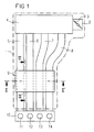
- An intake device 1 ( Figure 1) of an internal combustion engine comprises an intake manifold 2, in which a throttle valve 3 is arranged is.
- a first collector 4 communicates via the intake manifold 2 with the ambient air.
- Suction pipes 5, 6, 7, 8 are from the first collector 4 to a second collector 9 Inlets of the cylinders 11, 12, 13, 14 out.
- the cylinders 11, 12, 13, 14 are arranged in an engine block 10.
- switching flaps 20, 21, 22 are stored ( Figure 2).
- a company size like for example a speed N of a crankshaft, not shown and / or an air mass flow and / or an intake manifold pressure the switching flaps 20, 21, 22 in an open position or pivoted a closed position.
- the switching flaps 20, 21, 22 communicate the suction pipes 5, 6, 7, 8 through the openings together so that the effective intake manifold length, i.e. the area with continuous Flow in the intake manifold, the distance of the openings to the Inlets of the cylinders 11, 12, 13, 14 corresponds.
- the switch flaps close the switch flaps the openings between the suction pipes 5, 6, 7, 8, so that the effective length of the suction pipes is the length of the suction pipes from the first manifold 4 to the cylinder inlets 11, 12, 13, 14 corresponds.
- the construction of the switching flaps 20, 21, 22 is identical. in the The following is an example of the structure of the switching flap 20 described.
- the switching flap 20 ( Figure 3) has a shaft 23, which is bent at right angles at one free end. This is a simple pivoting between the open position and the closed position when installed a linkage, not shown, is possible, that of one also Actuator, not shown, is driven.
- the actuator is preferably a pressure cell or an electric motor.
- On the shaft 23 are at a predetermined distance a first sleeve 24 and a second sleeve 25 are applied.
- the first and second sleeve 24, 25 are designed to fit and serve for storage in a bearing bush 45, 46 ( Figure 6).
- a first and a second are preferred Damping ring 28, 29 applied to the shaft so that it with the first and the second sleeve 24, 25 for Facility is coming.
- the shaft 23 is form-fitting with a wing body 30 connected.
- the positive locking is done by embossing lugs 23a, b causes.
- the shaft 23 and the wing body 30 are accordingly rigidly connected.
- the wing body 30 is moreover provided with cutouts 31, 32, 33, 34.
- a sealant is injected around the wing body 30 and formed so that they edge of the switching flap forms a sealing lip 37 which in Closed state with a system collar of the opening to the system comes and thus closes the opening tightly.
- sealing compound forms a first and a second sealing hood 39, 40 at the opposite axial ends of the Switch flap 20 are arranged concentrically to the shaft 23.
- the sealing hoods 39, 40 are each open to the side, which faces away from the switching flap 20. On the side that the Switch flap is facing, they are form-fitting with the Switch flap connected.
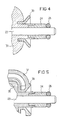
- FIG. 4 shows an enlarged detail of the switching flap 20 in a section along the axis of rotation of the switching flap.
- the Sealing hood 39 is conical. It is made of elastic Material, preferably made of an elastomer plastic.
- the sealing hood 39 can advantageously also be paraboloidal, be hemispherical or cylindrical.
- Figure 5 shows a preferred embodiment of the switching flap 20 in an enlarged detail in a sectional view along the axis of rotation of the switching flap 20.
- the sealing hood 39 protrudes in the form of a bead over the sealing lip 37.
- Figure 6 is a sectional view taken along a section line III - III 'according to Figure 1.
- the first and second bearing bush 45, 46 are preferably made of bronze and a perfect fit for the first and second sleeves 24, 25.
- the switching flap is in figure 6 shown in their open state.
- the first and the second sealing hood 39, 40 are against the first and the second bearing bush 45, 46 pressed, however, due to their elasticity migrate outwards depending on the contact pressure. So an axial seal of the Switch flap causes around the bearing bush.
- the sealing hood 39, 40 dampens moreover caused by vibrations of the internal combustion engine and from the first or second bearing bush 45, 46 and the first and second sleeves 24, 25 generated Sounds.
- the sealing hood 39, 40 also dampens an overcurrent noise caused by the rattling of the switching flap 20 and pressure differences between the suction pipes 5, 6 is strongly induced. This is a major advantage because the overcurrent noise can be heard as an unpleasant whistle will and increasingly strict legal regulations apply, the limit values for the amplitude of a motor vehicle define sound waves generated.
- the manufacture of the switching flap is described below.
- the shaft 23 ( Figure 7) bent at a free end at right angles and provided with embossing tabs 23a, b.
- the wave points in an inexpensive Embodiment larger manufacturing tolerances on.
- the shaft is not machined.
- the first sleeve 24 and the second sleeve 25 at a predetermined axial distance from the shaft 23 applied and radially pressed.
- the sleeves are preferred designed to fit the bearing bushes.
- a second step (FIG. 8), the shaft 23 introduced into an injection mold and the shaft 23 between the first and second sleeves 24, 25 with a thermoplastic Injection molded plastic so that the wing body 30 forms.
- the embossing lugs 23a, b ensure that the Wing body 30 is positively connected to the shaft.
- the wing body has a plurality of cutouts 31, 32, 33, 34 on.
- the wing body ( Figure 9) with a sealing compound, which are preferably formed as an elastomer plastic is overmolded such that the edge of the wing body forms a sealing lip.
- the injection molding is preferably carried out with the sealing compound in such a way that the opposite axial ends of the wing body 30 the first and the Form second sealing hood 39, 40.
- the wing body 30 will completely overmoulded with the sealing compound.
- the sealing lip 37 and the first and second sealing hoods 39, 40 are accordingly in produced by a spraying process.
- the recesses 31, 32, 33, 34 are preferably elongated holes executed and are after the encapsulation with the sealing compound filled. This is a positive connection with the wing body guaranteed. This has the advantage that there is no adhesive or fasteners must be used on a vulcanizing can be dispensed with and the sealing compound too tight when there is high frictional forces caused by a flowing fluid act on them.
- the manufacturing method described has the advantage that the switching flap is manufactured in very few manufacturing steps can be and the shift flap is light weight but still has a high mechanical durability. If the shaft is made of steel, there is high rigidity the switching flap guaranteed. In addition, the sealing behavior the switching flap optimized.
- the wing flap can alternatively also have three or four arms be trained.
- the invention is not based on the exemplary embodiments shown here limited.
Landscapes
- Engineering & Computer Science (AREA)
- Mechanical Engineering (AREA)
- General Engineering & Computer Science (AREA)
- Chemical & Material Sciences (AREA)
- Combustion & Propulsion (AREA)
- Manufacturing & Machinery (AREA)
- Characterised By The Charging Evacuation (AREA)
Abstract
Description
- Figur 1
- eine Brennkraftmaschine,
- Figur 2
- einen Schnitt der Brennkraftmaschine gemäß Figur 1 längs der Schnittlinie II - II'
- Figur 3
- eine mit dem erfindungsgemäßen Verfahren hergestellte Schaltklappe,
- Figur 4
- eine Ausschnittsvergrößerung der Schaltklappe längs eines Schnittes entlang der Drehachse der Schaltklappe,
- Figur 5
- eine weitere Ausschnittsvergrößerung der Schaltklappe in einer Schnittbilddarstellung,
- Figur 6
- einen Schnitt längs einer Schnittlinie III - III' der Brennkraftmaschine gemäß Figur 1,
- Figur 7
- einen ersten Arbeitsschritt zur Herstellung der Schaltklappe,
- Figur 8
- einen zweiten Arbeitsschritt zur Herstellung der Schaltklappe,
- Figur 9
- einen dritten Arbeitsschritt zur Herstellung der Schaltklappe.
Claims (6)
- Verfahren zum Herstellen einer Schaltklappe (20,21,22), die einen Flügelkörper (30) aufweist, der mit einer Welle (23) längs ihrer Drehachse verbunden ist, bei dem:eine erste Hülse (24) und eine zweite Hülse (25) in einem vorgegebenen axialen Abstand auf die Welle (23) aufgebracht werden und radial verpreßt werden,die Welle (23) zwischen der ersten und der zweiten Hülse (24, 25) mit einem thermoplastischen Kunststoff derart umspritzt wird, daß sich der Flügelkörper (30) bildet, der mindestens eine Aussparung (31) aufweist, undder Flügelkörper (30) mit einer Dichtmasse derart umspritzt wird, daß sich randseitig an dem Flügelkörper (30) eine Dichtlippe (37) bildet.
- Verfahren nach Anspruch 1, dadurch gekennzeichnet, daß die Welle (23) an einer Stelle zwischen der ersten und der zweiten Hülse (24, 25) derart verquetscht wird, daß sie eine Prägenase (23a, 23b) aufweist.
- Verfahren nach Anspruch 1, dadurch gekennzeichnet, daß der Flügelkörper (30) mit der Dichtmasse derart umspritzt wird, daß sich an den gegenüberliegenden axialen Enden des Flügelkörpers (30) eine erste und eine zweite Dichthaube (39, 40) ausbilden.
- Verfahren nach Anspruch 1, dadurch gekennzeichnet, daß jeweils ein Dämpfungsring (28,29) auf die Welle (23) an der dem Flügelkörper (30) abgewandten Seite der Hülse (24, 25) aufgebracht wird, so daß er mit der Hülse (24, 25) zur Anlage kommt.
- Verfahren nach Anspruch 1, dadurch gekennzeichnet, daß die Aussparung (31) als Langloch ausgebildet ist.
- Verfahren nach Anspruch 1, dadurch gekennzeichnet, daß die Welle (23) an einem freien Ende gekröpft wird.
Applications Claiming Priority (3)
| Application Number | Priority Date | Filing Date | Title |
|---|---|---|---|
| DE29704180U | 1997-03-07 | ||
| DE29704180 | 1997-03-07 | ||
| PCT/DE1998/000292 WO1998040615A1 (de) | 1997-03-07 | 1998-02-03 | Verfahren zum herstellen einer schaltklappe |
Publications (2)
| Publication Number | Publication Date |
|---|---|
| EP0964987A1 EP0964987A1 (de) | 1999-12-22 |
| EP0964987B1 true EP0964987B1 (de) | 2002-05-15 |
Family
ID=8037133
Family Applications (1)
| Application Number | Title | Priority Date | Filing Date |
|---|---|---|---|
| EP98907883A Expired - Lifetime EP0964987B1 (de) | 1997-03-07 | 1998-02-03 | Verfahren zum herstellen einer schaltklappe |
Country Status (3)
| Country | Link |
|---|---|
| EP (1) | EP0964987B1 (de) |
| DE (4) | DE19717347C1 (de) |
| WO (1) | WO1998040615A1 (de) |
Families Citing this family (10)
| Publication number | Priority date | Publication date | Assignee | Title |
|---|---|---|---|---|
| DE19848440A1 (de) * | 1998-10-21 | 2000-04-27 | Mann & Hummel Filter | Klappenmechanismus |
| DE19918777A1 (de) * | 1999-04-24 | 2000-10-26 | Mann & Hummel Filter | Schaltklappenverband aus montagegespritzten Schaltklappen oder Klappenmodulen |
| DE19919661A1 (de) * | 1999-04-29 | 2000-11-02 | Volkswagen Ag | Sauganlage für eine Verbrennungsluftversorgung einer Brennkraftmaschine |
| DE19936456A1 (de) * | 1999-08-03 | 2001-02-08 | Mann & Hummel Filter | Ventil |
| DE19951082B4 (de) * | 1999-10-23 | 2013-05-29 | Mann + Hummel Gmbh | Saugrohr mit einer Schaltwalze |
| EP1299627B1 (de) | 2000-07-11 | 2006-06-07 | Siemens Aktiengesellschaft | Schaltklappe |
| DE20017044U1 (de) * | 2000-10-04 | 2002-02-14 | ASV Stübbe GmbH & Co. KG, 32602 Vlotho | Bauteil aus Kunststoff |
| DE10131109A1 (de) * | 2001-06-27 | 2003-01-09 | Mann & Hummel Filter | Verfahren zur Herstellung eines Schaltklappenverbandes |
| DE10303701B4 (de) * | 2003-01-30 | 2012-02-16 | Siemens Ag | Verfahren und Vorrichtung zum Steuern einer Brennkraftmaschine |
| DE10328246B4 (de) * | 2003-06-24 | 2007-04-26 | Pierburg Gmbh | Kraftfahrzeugventil |
Family Cites Families (16)
| Publication number | Priority date | Publication date | Assignee | Title |
|---|---|---|---|---|
| US724812A (en) | 1902-12-26 | 1903-04-07 | Anna C Cloud | Device for correcting facial defects. |
| DE1282381B (de) * | 1962-10-31 | 1969-03-27 | Betts Machine Company | Absperr-Drosselklappe |
| US3724812A (en) * | 1971-11-17 | 1973-04-03 | Fastener Corp | Damper assembly |
| US3753549A (en) * | 1972-12-11 | 1973-08-21 | Arco Ind Corp | Flow control device and method and apparatus for making same |
| CH641259A5 (de) * | 1979-10-09 | 1984-02-15 | Fischer Ag Georg | Absperrklappe. |
| DE3034603A1 (de) * | 1980-09-13 | 1982-04-29 | Leonhard Schleicher Südmo-Armaturenfabrik GmbH, 7081 Riesbürg | Absperrklappe |
| GB2093955A (en) * | 1981-02-25 | 1982-09-08 | Clearplas Ltd | Fluid flow controlling valves |
| FR2505010B1 (fr) * | 1981-05-04 | 1985-06-14 | Valeo | Dispositif pour la commande d'un appareil de chauffage et de degivrage de vehicule automobile |
| JPS61140675A (ja) * | 1984-12-07 | 1986-06-27 | Tomoe Gijutsu Kenkyusho:Kk | バタフライ弁のシ−ル装置 |
| FR2613428B1 (fr) * | 1987-03-30 | 1992-05-22 | Peugeot | Moteur alimente par injection, a circuit d'admission perfectionne |
| DE4041786C2 (de) * | 1990-12-24 | 2003-04-30 | Opel Adam Ag | Für eine Brennkraftmaschine bestimmte Ansauganlage |
| EP0494344A1 (de) * | 1991-01-09 | 1992-07-15 | Firma Carl Freudenberg | Dichtsystem für Drosselklappenkonstruktion mit Vollwelle |
| FR2687601A1 (fr) * | 1992-02-26 | 1993-08-27 | Plastic Omnium Cie | Procede de fabrication d'une vanne papillon, dispositif pour le mettre en óoeuvre et vanne papillon obtenue par ce procede. |
| WO1996007022A1 (de) * | 1994-08-31 | 1996-03-07 | Siemens Aktiengesellschaft | Variable luftansaugvorrichtung |
| US5531248A (en) * | 1995-01-19 | 1996-07-02 | Eaton Corporation | Butterfly valve |
| DE19516927A1 (de) * | 1995-05-09 | 1996-11-14 | Mann & Hummel Filter | Drosselklappendichtung |
-
1997
- 1997-04-24 DE DE19717347A patent/DE19717347C1/de not_active Expired - Fee Related
- 1997-04-24 DE DE19717350A patent/DE19717350A1/de not_active Withdrawn
- 1997-04-24 DE DE19717349A patent/DE19717349A1/de not_active Withdrawn
-
1998
- 1998-02-03 WO PCT/DE1998/000292 patent/WO1998040615A1/de not_active Ceased
- 1998-02-03 EP EP98907883A patent/EP0964987B1/de not_active Expired - Lifetime
- 1998-02-03 DE DE59804142T patent/DE59804142D1/de not_active Expired - Fee Related
Also Published As
| Publication number | Publication date |
|---|---|
| DE19717350A1 (de) | 1998-09-24 |
| DE19717347C1 (de) | 1998-08-20 |
| WO1998040615A1 (de) | 1998-09-17 |
| EP0964987A1 (de) | 1999-12-22 |
| DE59804142D1 (de) | 2002-06-20 |
| DE19717349A1 (de) | 1998-09-24 |
Similar Documents
| Publication | Publication Date | Title |
|---|---|---|
| EP1371832B1 (de) | Regelklappe mit umgespritzter Welle | |
| EP0678157B1 (de) | Drosselvorrichtung | |
| EP0726388B1 (de) | Ansaugsystem | |
| WO1995006808A1 (de) | Drosseleinrichtung | |
| DE102004056764B4 (de) | Drosselkörper und Verfahren zum Herstellen solcher Drosselkörper | |
| DE19717347C1 (de) | Verfahren zum Herstellen einer Schaltklappe | |
| EP0977936B1 (de) | Ansaugeinrichtung | |
| WO2001009498A1 (de) | Ventil | |
| EP0494344A1 (de) | Dichtsystem für Drosselklappenkonstruktion mit Vollwelle | |
| EP1200722B1 (de) | Drosseleinrichtung mit einer klappe zum einbau in eine flanschverbindung | |
| DE102005031129A1 (de) | Einlasssteuervorrichtung für eine Brennkraftmaschine | |
| EP0891486B1 (de) | Ansaugsystem für einen verbrennungsmotor | |
| EP1299627B1 (de) | Schaltklappe | |
| DE102012107840B4 (de) | Umschaltventil und Verfahren zur Herstellung desselben | |
| DE19753390A1 (de) | Stapelförmig angeordneter, schneckenförmiger Krümmer | |
| DE19819364B4 (de) | Drosselklappe | |
| WO2007128669A2 (de) | Verfahren zur herstellung einer drosselklappeneinheit sowie drosselklappeneinheit | |
| EP1251253B1 (de) | Schaltverband zum Verschluss von Saugkanälen einer Ansaugvorrichtung | |
| EP1291504A2 (de) | Schaltklappeneinrichtung | |
| EP1419330B1 (de) | Drosselklappenstutzen für einen verbrennungsmotor | |
| WO2018206762A1 (de) | Drehgelenkanordnung mit einem mittels spritzguss gefertigten gelenkbolzen | |
| WO1997023714A1 (de) | Luftansaugvorrichtung mit variabler saugrohrlänge für eine brennkraftmaschine | |
| EP1167716B1 (de) | Luftansaugkanalsystem für eine Brennkraftmaschine | |
| DE102008055628A1 (de) | Verfahren zur Herstellung eines Klappenverbandes | |
| DE4240510A1 (de) | Drehschwingungstilger |
Legal Events
| Date | Code | Title | Description |
|---|---|---|---|
| PUAI | Public reference made under article 153(3) epc to a published international application that has entered the european phase |
Free format text: ORIGINAL CODE: 0009012 |
|
| 17P | Request for examination filed |
Effective date: 19990903 |
|
| AK | Designated contracting states |
Kind code of ref document: A1 Designated state(s): DE FR IT |
|
| GRAG | Despatch of communication of intention to grant |
Free format text: ORIGINAL CODE: EPIDOS AGRA |
|
| GRAG | Despatch of communication of intention to grant |
Free format text: ORIGINAL CODE: EPIDOS AGRA |
|
| GRAH | Despatch of communication of intention to grant a patent |
Free format text: ORIGINAL CODE: EPIDOS IGRA |
|
| 17Q | First examination report despatched |
Effective date: 20010704 |
|
| GRAH | Despatch of communication of intention to grant a patent |
Free format text: ORIGINAL CODE: EPIDOS IGRA |
|
| GRAA | (expected) grant |
Free format text: ORIGINAL CODE: 0009210 |
|
| AK | Designated contracting states |
Kind code of ref document: B1 Designated state(s): DE FR IT |
|
| REF | Corresponds to: |
Ref document number: 59804142 Country of ref document: DE Date of ref document: 20020620 |
|
| ET | Fr: translation filed | ||
| PLBE | No opposition filed within time limit |
Free format text: ORIGINAL CODE: 0009261 |
|
| STAA | Information on the status of an ep patent application or granted ep patent |
Free format text: STATUS: NO OPPOSITION FILED WITHIN TIME LIMIT |
|
| 26N | No opposition filed |
Effective date: 20030218 |
|
| PGFP | Annual fee paid to national office [announced via postgrant information from national office to epo] |
Ref country code: DE Payment date: 20090219 Year of fee payment: 12 |
|
| PGFP | Annual fee paid to national office [announced via postgrant information from national office to epo] |
Ref country code: IT Payment date: 20090221 Year of fee payment: 12 |
|
| PGFP | Annual fee paid to national office [announced via postgrant information from national office to epo] |
Ref country code: FR Payment date: 20090213 Year of fee payment: 12 |
|
| REG | Reference to a national code |
Ref country code: FR Ref legal event code: ST Effective date: 20101029 |
|
| PG25 | Lapsed in a contracting state [announced via postgrant information from national office to epo] |
Ref country code: FR Free format text: LAPSE BECAUSE OF NON-PAYMENT OF DUE FEES Effective date: 20100301 |
|
| PG25 | Lapsed in a contracting state [announced via postgrant information from national office to epo] |
Ref country code: DE Free format text: LAPSE BECAUSE OF NON-PAYMENT OF DUE FEES Effective date: 20100901 |
|
| PG25 | Lapsed in a contracting state [announced via postgrant information from national office to epo] |
Ref country code: IT Free format text: LAPSE BECAUSE OF NON-PAYMENT OF DUE FEES Effective date: 20100203 |