EP0964315B1 - Image heating apparatus - Google Patents
Image heating apparatus Download PDFInfo
- Publication number
- EP0964315B1 EP0964315B1 EP99111233A EP99111233A EP0964315B1 EP 0964315 B1 EP0964315 B1 EP 0964315B1 EP 99111233 A EP99111233 A EP 99111233A EP 99111233 A EP99111233 A EP 99111233A EP 0964315 B1 EP0964315 B1 EP 0964315B1
- Authority
- EP
- European Patent Office
- Prior art keywords
- heater
- time
- turned
- constant
- constant voltage
- Prior art date
- Legal status (The legal status is an assumption and is not a legal conclusion. Google has not performed a legal analysis and makes no representation as to the accuracy of the status listed.)
- Expired - Lifetime
Links
- 238000010438 heat treatment Methods 0.000 title claims description 18
- 230000000630 rising effect Effects 0.000 claims description 20
- 230000002093 peripheral effect Effects 0.000 description 8
- 238000010276 construction Methods 0.000 description 7
- 239000003990 capacitor Substances 0.000 description 5
- 238000010586 diagram Methods 0.000 description 4
- 229910052736 halogen Inorganic materials 0.000 description 4
- 150000002367 halogens Chemical class 0.000 description 4
- 238000000034 method Methods 0.000 description 4
- 238000007599 discharging Methods 0.000 description 2
- 230000000694 effects Effects 0.000 description 2
- 230000001419 dependent effect Effects 0.000 description 1
- 238000011161 development Methods 0.000 description 1
- 230000018109 developmental process Effects 0.000 description 1
- 230000003993 interaction Effects 0.000 description 1
Images


Classifications
-
- G—PHYSICS
- G03—PHOTOGRAPHY; CINEMATOGRAPHY; ANALOGOUS TECHNIQUES USING WAVES OTHER THAN OPTICAL WAVES; ELECTROGRAPHY; HOLOGRAPHY
- G03G—ELECTROGRAPHY; ELECTROPHOTOGRAPHY; MAGNETOGRAPHY
- G03G15/00—Apparatus for electrographic processes using a charge pattern
- G03G15/20—Apparatus for electrographic processes using a charge pattern for fixing, e.g. by using heat
- G03G15/2003—Apparatus for electrographic processes using a charge pattern for fixing, e.g. by using heat using heat
Definitions
- This invention relates to an image heating apparatus for use as a fixing device of a copying apparatus or a printer.
- an image heating apparatus of this kind has a heater supplied with electric power from a commercially available power source and generating heat, and is temperature-controlled so that a temperature of this heater or a temperature of a fixing roller heated by this heater may maintain a predetermined level.
- a soft start of the heater of a fixing device is known for example from US-A-3 989 370.
- the present invention has been made in view of the above-noted problem and an object thereof is to provide an image heating apparatus which can suppress the flicker occurring to an illuminator or the like.
- Fig. 1 is a typical cross-sectional view schematically showing the construction of a laser beam printer 37 (hereinafter referred to as the printer 37) which is an example of an image forming apparatus provided with an image heating apparatus of the present invention.
- the printer 37 a laser beam printer 37 (hereinafter referred to as the printer 37) which is an example of an image forming apparatus provided with an image heating apparatus of the present invention.
- the printer 37 is provided with a drum-shaped photosensitive member 38 on the outer peripheral surface of which an electrostatic latent image is formed, a roller-shaped charging member 39 for charging the outer peripheral surface of the photosensitive member 38 to prescribed potential, a laser scanner unit 40 for forming an electrostatic latent image on said outer peripheral surface charged to the prescribed potential, by exposure, a developing device 41 for making the electrostatic latent image into a visible image by a developer, a roller-shaped transferring member 42 for transferring the visible image (visualized image) formed on said outer peripheral surface to recording paper P which is a sheet of recording medium, and a fixing device 43 which is an image heating apparatus.
- the laser scanner unit 40 first effects exposure on the outer peripheral surface of the photosensitive member 38 charged to the prescribed potential by the charging member 39, whereby an electrostatic latent image conforming to image information given from the outside to the printer 37 is formed on said outer peripheral surface.
- the electrostatic latent image formed on the outer peripheral surface of the photosensitive member 38 is given a developer from the developing device 41, whereby it is visualized into a visible image.
- the recording paper P on which image information conforming to the given image information is recorded is fed at predetermined timing or the like from a cassette 45 removably supported on the body of the printer 37 or a multipaper tray 44 disposed on one side of the printer 37 to a transfer nip portion TN formed between the photosensitive member 38 and the transferring member 42.
- the visualized image formed and borne on the outer peripheral surface of the photosensitive member 38 is transferred to the recording paper P having arrived at the transfer nip portion TN by electrical interaction from the transferring member 42.
- the recording paper P bearing the visualized image in its unfixed state on one surface thereof (hereinafter the visualized image in its unfixed state will be referred to as the unfixed image) is supplied with heat and given pressure at the fixing device 43, whereby the unfixed image is melted and fixed, whereby an image conforming to the given image information is recorded on the recording paper P, and the recording paper P now having the image formed thereon is discharged onto a paper discharging tray 46 disposed on the other side of the body of the printer 37.
- Fig. 2 is a typical cross-sectional view schematically showing the construction of the fixing device 43 in the present embodiment
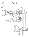
- Fig. 3 is a block diagram showing the signal routes of the fixing device and a temperature control system in the present embodiment.
- the fixing device 43 has a heater which is heating means receiving electric power from a commercially available power source and generating heat, a thermistor 34 which is a temperature detecting member for detecting the temperature of the heater 1, a fixing roller 48 which is a fixing member conducting the heat from the heater 1, and a pressing roller 49 which is a pressing member urged against the fixing roller 48.
- a control portion 47 mounted on the body of the printer 37 provided with the fixing device 43 is provided with a constant voltage output circuit 2 which is adjusting means for changing over to the conduction or shut-off from the commercially available power source to the heater 1 with a time constant, and an MPU 13 which is control means for controlling the changeover of the constant voltage output circuit 2 in conformity with the temperature detected by the thermistor 34.
- the fixing device 43 is adapted to pass the recording paper P bearing the unfixed image thereon to the nip portion N provided by the pressure contact between the fixing roller 48 and the pressing roller 49 to thereby fix the unfixed image on the recording paper P by the heat of the heater 1 through the fixing roller 48.
- the constant voltage output circuit 2 has a voltage dropping type DC-DC converter comprising a chopping FET 3, an inductor 4 and a diode 5 for a snubber.
- the constant voltage output circuit 2 is designed such that a control IC 6 (in the present embodiment, UC 3854 produced by UNITRODE Inc. is used) for detecting an output voltage and an output current to the heater and an input root mean square value voltage and an input voltage waveform from the commercially available power source detects the above-mentioned output voltage by a voltage detecting circuit 7, detects the above-mentioned output current by a current detecting resistor, detects the above-mentioned input root mean square value by a resistor 9 and a capacitor 10, and detects the input voltage waveform by a resistor 11 and a resistor 12, and is adapted to control the ON duty of the chopping FET 3 being turned on/off by about 100 kHz so that the output voltage may become constant and the output current waveform may become a waveform similar to the input current waveform.
- a control IC 6 in the present embodiment, UC 3854 produced by UNITRODE Inc.
- the MPU 13 is provided with a timer, a ROM, a RAM, input and output ports (all not shown), etc., and a digital output port P1 provided in the MPU 13 is connected to the base of a transistor 15 through a resistor 14, and a signal from the digital output port P1 is made HIGH, whereby the transistor 15 is turned on, a photodiode 17 connected to a +5 V power source through a resistor 16 is turned on, a phototransistor 18 is turned on and a transistor 20 is turned off through a resistor 19, whereby the voltage of a voltage source Vcc is inputted to the enable terminal ENA of the control IC 6 through a resistor 21 to thereby operate the control IC 6 so as to control the constant voltage output.
- a transistor 23 is also turned off through a diode 22, and a capacitor 24 connected to a soft start terminal SS provided in the control IC 6 is charged by a constant current power source in the control IC 6, and the potential of the soft start terminal SS rises in the fashion of a primary function, whereby the output voltage of the constant voltage output circuit 2 also rises with a predetermined time constant.
- the output of the constant voltage output circuit 2 when the output of the constant voltage output circuit 2 is put off, the charge of the capacitor 24 is discharged by a constant current discharging circuit comprised of a resistor 26, a resistor 27 and a resistor 28 and therefore, the potential of the soft start terminal SS drops in the fashion of a primary function, and the output voltage of the constant voltage output circuit also drops with a predetermined time constant.
- a capacitor 29 and a diode 36 connected to the base of the transistor 20 are designed such that when the phototransistor 18 of a photocoupler PC1 is turned off, the transistor 20 for enable control is turned off with a predetermined delay time relative to the transistor 23 for soft start control, and a resistor 30 is a pull-up resistor for turning on the transistor 20 and the transistor 23.
- the constant voltage output circuit 2 is connected to the commercially available power source 33 through a diode bridge 31 and a noise filter 32, and the MPU 13 detects the temperature of the heater by the thermistor 34 and the resistor 35, and controls the ON/OFF of the constant voltage output circuit 2 in conformity with this detected temperature, thereby adjusting the temperature of the heater so as to become a target temperature.
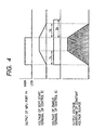
- the MPU 13 outputs a HIGH signal from the output port P1 to the constant voltage output circuit 2, whereby the voltage of the soft start terminal of the control IC 6 linearly rises with a time constant Tu.
- the MPU 13 outputs a LOW signal from the output port P1 to the constant voltage output circuit 2, whereby the voltage of the soft start terminal linearly drops with a time constant Td, whereafter in a time Te, the enable terminal becomes LOW and the control IC 6 stops.
- the voltage of the above-described electric power supply is put ON/OFF in the fashion of a primary function with a predetermined time constant, whereby a sudden increase or decrease in the electric current by the changeover of the electric power supply can be alleviated and flicker can be prevented.
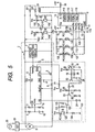
- Fig. 5 is a circuit diagram showing the construction of the fixing device in the present embodiment.
- the fixing device in the present embodiment has a halogen heater 101 (hereinafter referred to as the heater 101) and a halogen heater 102 (hereinafter referred to as the heater 102) which are two heating means, and the heater 101 is connected to the constant voltage output circuit 2 and an FET 107 which is a switching element, and the heater 102 is connected to the constant voltage output circuit 2 and an FET 104 which is a switching element.
- the heater 101 halogen heater 101
- FET 107 which is a switching element
- FET 104 which is a switching element
- the heater 101 is connected to the constant voltage output circuit 2 by the FET 107 becoming conductive, whereby electric power supply is effected, and heater 102 is connected to the constant voltage output circuit 2 by the FET 104 becoming conductive, whereby electric power supply is effected.
- the phototransistor 103 of a photocoupler PC 101, the phototransistor 106 of a photocoupler PC 102, a pull-up resistor 105 and a pull-up resistor 108 are connected to the gates of the FET 104 and the FET 107, respectively.
- the anode of the photodiode 110 of the photocoupler PC 101 and the anode of the photodiode 113 of the photocoupler PC 102 are connected to +5 V power source through a resistor 111 and a resistor 114, respectively, and the cathodes thereof are connected to the collectors of the transistors 109 and 112, respectively.
- the bases of the transistors 109 and 112 are connected to the digital output port P2 and output port P3, respectively, of an MPU 13 which is a microprocessor through a resistor 119 and a resistor 120, respectively, and the MPU 13 has a timer 115, a timer 116, a ROM 117, a RAM 118, input and output ports (not shown), etc.
- the output ports P2 and P3 of the MPU 13 are made LOW, whereby the transistor 109 and the transistor 112 are turned off, and the photodiode 110 and the photodiode 113 are turned off.
- the heater 101 and the heater 102 are turned on, and these heaters are connected to the constant voltage output circuit 2 when signals outputted from the output ports P2 and P3 of the MPU 13 which effects the connection of the heaters 101 and 102 to the constant voltage output circuit 2 (hereinafter referred to as the connection signals of the heater 101 and the heater 102) are ON.
- a constant voltage is outputted when a signal outputted from the output port P1 of the MPU 13 which controls the enable terminal ENA of a control IC 6 (hereinafter referred to as the constant voltage output control signal) is ON, and the respective heaters are turned on only when all of the constant voltage output control signal and the heater connection signals are ON.
- a constant current source 121 is provided in parallel to the soft start terminal SS of the control IC 6 to change over the time constant for the rising of the constant voltage output, and the control of this constant current source 121 is effected by the output port P4 of the MPU 13, and when the output port P4 is HIGH, the photodiode 128 of the photocoupler PC 103 is turned off and a phototransistor 122 is also turned off and a transistor 126 is turned on.
- a constant current determined by a voltage divided by a resistor 123 and a resistor 124 and a resistor 125 charges a capacitor 24 with a supplied current from the soft stat terminal SS of the control IC 6, whereby it becomes possible to change over the time constant for the rising to two stages Tu1 and Tu2 (Tu1 ⁇ Tu2).
- the case of the time constant Tu1 for the rising is called a short mode, and the case of the time constant Tu2 for the rising is called a long mode, and the short mode is brought about when the signal of the output port P4 of the MPU 13 which changes over the time constant for the rising (hereinafter referred to as the time-constant-changeover-signal) is ON.
- the time constant changeover signal is put off and the constant current source 121 is not operated, and is always made to fall with a time constant Td.
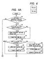
- Figs. 6A and 6B are flowcharts showing the processing procedure of heater control effected by the MPU 13.
- step S3 When the constant voltage output circuit is outputting a constant voltage and the heaters are turned on, the constant voltage output circuit is turned off (step S3), and waits for a time Tw until its output voltage is completely put off (S4), and on the other hand, if the constant voltage output circuit is not outputting the constant voltage, shift is made to a step S5.
- step S5 how the state of the heater 101 is changed is discriminated (S5), and first, when the heater 101 is to be changed from ON to OFF, the connection between the constant voltage output circuit 2 and the heater 101 is shut off (the heater 101 connection signal is OFF) (step S6), and the timer 115 for measuring the OFF time of the heater 101 is started (S7).
- step S8 when the heater 101 is to be changed from OFF to ON, the timer 115 which has measured the OFF time of the heater 101 is stopped so that a RAM 118 stores the value as Tloff (step S8), and the timer 115 is cleared (step S9), and the heater 101 is connected with the constant voltage output circuit 2 (the heater connection signal is ON) (step S10).
- processing (S11 to S16) similar to the above-described processing (S5 to S10) of the heater 101 is effected on the heater 102.
- connection signals of the heater 101 and the heater 102 are both OFF is discriminated (S17), and if both are OFF, the program ends, and if at least one of the heaters are connected, whether T1off or T2off stored in the RAM 118 is greater than a threshold value Tth stored in the ROM 117 is first discriminated (S18).
- Tloff or T2off stored in the RAM 118 is greater than the threshold value Tth stored in the ROM 117, the mode is judged to be the long mode and the constant voltage output circuit is turned on (S19), and in any other case, the mode is judged to be the short mode and the-time-constant-changeover-signal is turned on (S20) and the constant voltage output is turned on (S21).
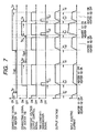
- Fig. 7 is a timing chart showing the waveforms of the control signals during the ON/OFF of the heaters.
- Fig. 7 shows the connection signals of the heater 101 and the heater 102, the output control signal of the constant voltage output circuit 2, the time-constant-changeover-signal, the output voltage Vout of the constant voltage output circuit 2 and the input current from the commercially available power source 33 when the heater 101 is turned off from a state in which the heater 101 is ON and the heater 102 is OFF, and subsequently the heater 102 is turned on, and then is turned off, and the heater 102 is turned on from a state in which the heater 101 is ON, and subsequently the heater 102 is turned off and the heater 101 is turned off.
- the connection signal of the heater 101 and the constant voltage output control signal are ON, and a constant voltage is outputted from the constant voltage output circuit 2, and the input current also is constant, and the heater 102 is OFF and therefore, the timer 116 for measuring the OFF time of the heater 102 is operating.
- the constant voltage output control signal is first turned off, whereby the output voltage falls with a predetermined time constant Td by the falling function, and after a time Tw from a tme when the constant voltage output control signal is turned off (Tw > Td), the connection signal of the heater 101 is also turned off and the timer 115 is started and begins to measure the OFF time of the heater 101.
- the timer 116 which has so far operated is first stopped because the constant voltage is not outputted, and the OFF time of the heater 102 is found, whereafter the connection signal of the heater 102 is turned on, and the mode is set to the long mode when that connection signal is long as compared with the threshold value Tth stored in the ROM 117, and the mode is set to the short mode when that connection signal is short as compared with the threshold value Tth.
- the connection signal is shorter than the threshold value Tth and the mode is set to the short mode.
- the time-constant-changeover-signal is turned on and the constant voltage output control signal is turned on, whereby the constant voltage output circuit 2 begins to operate, and the output voltage rises with the time constant Tu1.
- the time-constant-changeover-signal and the constant current source 121 operated thereby can be ON only during the rising and therefore, at a point of time whereat the time Tu1 has passed after the constant voltage output control signal has been turned on, the time-constant-changeover-signal is turned off and after a predetermined time from that time, the heater 102 is turned off, and as in the case of the heater 101, the constant voltage output control signal is first turned off and the output voltage is made to fall with the predetermined time constant Td.
- connection signal of the heater 102 is also turned off, and the timer 116 is started and begins to measure the OFF time of the heater 102.
- the heater 101 is again turned on, and as in the above-described case, the timer 115 is stopped to thereby find the OFF time Tloff of the heater 101, and Tloff is compared with the threshold value Tth, and since in the present embodiment, Tloff is longer than the threshold value Tth, the mode is the long mode, and the constant voltage output is turned on with the time-constant-changeover-signal remaining OFF, and is made to rise with the time constant Tu2.
- the heater 102 is turned on, but since the heater 101 is ON, the constant voltage output is once turned off to thereby make the output voltage fall with the time constant Td.
- the connection signal of the heater 101 remains ON.
- the timer 116 is stopped and the connection signal of the heater 102 is turned on.
- the OFF time T2off of the heater 102 is shorter than the threshold value Tth. Therefore, the mode becomes the short mode, and the time-constant-changeover-signal is turned on and the constant voltage output control is started and is made to rise with the time constant Tu1, and at this time, the connection signal of the heater 101 also is ON and therefore, the both heaters are ON and the input current becomes much.
- the heater 102 is turned off, but since the heater 101 is ON, the constant voltage output is once turned off and is made to fall with the time constant Td, and after the time Tw from that time, the connection signal of the heater 102 is turned off and simultaneously therewith, the timer 116 is started. The constant voltage output is then turned on, but the connection signal of the heater 101 remains ON and Tloff is 0.
- the output voltage is made to rise in the short mode, and after a predetermined time from that time, the heater 101 is turned off as hitherto described.
- the time constant for the rising from the commercially available power source to the heating means is changed over in conformity with the length of the time for which the heating means has been disconnected from the commercially available power source, whereby when use is made of such heat generating means as a halogen heater of which the resistance value is changed by the temperature of the heat generating portion thereof and in which a plunge current is created as the OFF time becomes longer, a sudden increase or decrease in the current of the commercially available power source can be alleviated more effectively.
- the present embodiment has been shown with respect to a case where two heaters are used, the present invention can be equally applied to a case where one or three or more heaters are used and further, the time constants for the rising are not limited to two kinds, but changeover may be done with three or more kinds of time constants.
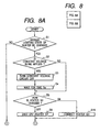
- FIG. 8A and 8B A third embodiment of the present invention will now be described with reference to Figs. 8A and 8B.
- this embodiment portions similar to those in the second embodiment are given the same reference characters and need not be described.
- Figs. 8A and 8B are flowcharts showing the processing procedure of the heater control in the present embodiment.
- the difference of the present embodiment from the second embodiment is that at S17, wherein the connection signals of the heater 101 and the heater 102 are both OFF is discriminated, whereafter whether the image forming apparatus is in a printing operation wherein the heater turn-on frequency is high and the turn-on interval is short or in waiting wherein the heater turn-on frequency is low and the turn-on interval is long is discriminated (S30), and if it is in waiting, the constant voltage output circuit is turned on while the mode remains being the long mode (S19), and if it is in printing, the time-constant-changeover-signal is turned on to bring about the short mode (S20), and the constant voltage output circuit is turned on (S21). After waiting for the time constant Tu1 for the rising (S22), the time-constant-changeover-signal is turned off (S23).
- the present embodiment has been shown with respect to a case where two heaters are used, the present invention can be equally applied to a case where one or three or more heaters are used and further, the time constants for the rising are not limited to two kinds, but changeover may be done with three or more kinds of time constants.
Landscapes
- Physics & Mathematics (AREA)
- General Physics & Mathematics (AREA)
- Fixing For Electrophotography (AREA)
- Control Or Security For Electrophotography (AREA)
- Control Of Resistance Heating (AREA)
- Resistance Heating (AREA)
- Control Of Temperature (AREA)
Applications Claiming Priority (2)
| Application Number | Priority Date | Filing Date | Title |
|---|---|---|---|
| JP10176577A JPH11354254A (ja) | 1998-06-10 | 1998-06-10 | 加熱装置、定着装置及びこの加熱装置を備える画像形成装置 |
| JP17657798 | 1998-06-10 |
Publications (3)
| Publication Number | Publication Date |
|---|---|
| EP0964315A2 EP0964315A2 (en) | 1999-12-15 |
| EP0964315A3 EP0964315A3 (en) | 2001-06-06 |
| EP0964315B1 true EP0964315B1 (en) | 2005-04-06 |
Family
ID=16016004
Family Applications (1)
| Application Number | Title | Priority Date | Filing Date |
|---|---|---|---|
| EP99111233A Expired - Lifetime EP0964315B1 (en) | 1998-06-10 | 1999-06-09 | Image heating apparatus |
Country Status (4)
| Country | Link |
|---|---|
| US (1) | US6449445B1 (enExample) |
| EP (1) | EP0964315B1 (enExample) |
| JP (1) | JPH11354254A (enExample) |
| DE (1) | DE69924562T2 (enExample) |
Cited By (1)
| Publication number | Priority date | Publication date | Assignee | Title |
|---|---|---|---|---|
| CN105404332A (zh) * | 2015-12-21 | 2016-03-16 | 周芸 | 可预置温度电加热暖脚毯 |
Families Citing this family (8)
| Publication number | Priority date | Publication date | Assignee | Title |
|---|---|---|---|---|
| JP2002222017A (ja) * | 2001-01-24 | 2002-08-09 | Canon Inc | 温度制御装置 |
| JP4289827B2 (ja) * | 2002-04-12 | 2009-07-01 | キヤノン株式会社 | 画像形成装置 |
| US6763206B2 (en) * | 2002-05-14 | 2004-07-13 | Kabushiki Kaisha Toshiba | Image forming apparatus with an induction heating fixing unit for shortening warm up time |
| KR101309785B1 (ko) * | 2006-07-28 | 2013-09-23 | 삼성전자주식회사 | 위상 제어 장치, 이를 구비한 정착기 제어 장치 및 위상제어 방법 |
| KR101656774B1 (ko) * | 2009-12-16 | 2016-09-12 | 삼성전자주식회사 | 전력 캡슐을 이용한 화상형성장치의 정착기 온도제어 방법 및 장치와 이를 구비하는 화상형성장치 |
| JP6452421B2 (ja) | 2014-12-08 | 2019-01-16 | キヤノン株式会社 | 画像形成装置 |
| US10522440B2 (en) * | 2017-11-07 | 2019-12-31 | Taiwan Semiconductor Manufacturing Co., Ltd. | Package structure and method of manufacturing the same |
| JP7703343B2 (ja) | 2021-03-19 | 2025-07-07 | キヤノン株式会社 | 画像形成装置 |
Citations (4)
| Publication number | Priority date | Publication date | Assignee | Title |
|---|---|---|---|---|
| US3989370A (en) * | 1975-04-01 | 1976-11-02 | Xerox Corporation | Adaptive fuser controller |
| JPS5746258A (en) * | 1980-09-05 | 1982-03-16 | Ricoh Co Ltd | Controlling system for electric power of copying machine |
| JPH05307338A (ja) * | 1992-04-30 | 1993-11-19 | Hitachi Koki Co Ltd | 電子写真方式プリンタ用定着ヒータの制御回路 |
| JPH1063135A (ja) * | 1996-08-23 | 1998-03-06 | Ricoh Co Ltd | 画像形成装置 |
Family Cites Families (9)
| Publication number | Priority date | Publication date | Assignee | Title |
|---|---|---|---|---|
| US4937600A (en) | 1987-07-29 | 1990-06-26 | Canon Kabushiki Kaisha | Image forming apparatus |
| JPH0748125B2 (ja) * | 1987-08-14 | 1995-05-24 | キヤノン株式会社 | 画像形成装置 |
| JPS6481976A (en) * | 1987-09-25 | 1989-03-28 | Konishiroku Photo Ind | Lamp turning-on circuit |
| JPH0259782A (ja) | 1988-08-25 | 1990-02-28 | Brother Ind Ltd | 画像形成装置 |
| EP0370520B1 (en) * | 1988-11-25 | 1994-08-24 | Canon Kabushiki Kaisha | An image fixing apparatus |
| JP2941827B2 (ja) | 1988-12-15 | 1999-08-30 | キヤノン株式会社 | 記録装置 |
| JP2673968B2 (ja) | 1990-07-10 | 1997-11-05 | キヤノン株式会社 | 温度制御装置 |
| US5436712A (en) * | 1993-12-16 | 1995-07-25 | Xerox Corporation | Power control for instant-on-integral resistive heating belt fuser |
| DE69638285D1 (de) | 1995-06-30 | 2010-12-16 | Canon Kk | Bildheizgerät |
-
1998
- 1998-06-10 JP JP10176577A patent/JPH11354254A/ja active Pending
-
1999
- 1999-06-04 US US09/325,559 patent/US6449445B1/en not_active Expired - Lifetime
- 1999-06-09 EP EP99111233A patent/EP0964315B1/en not_active Expired - Lifetime
- 1999-06-09 DE DE69924562T patent/DE69924562T2/de not_active Expired - Lifetime
Patent Citations (4)
| Publication number | Priority date | Publication date | Assignee | Title |
|---|---|---|---|---|
| US3989370A (en) * | 1975-04-01 | 1976-11-02 | Xerox Corporation | Adaptive fuser controller |
| JPS5746258A (en) * | 1980-09-05 | 1982-03-16 | Ricoh Co Ltd | Controlling system for electric power of copying machine |
| JPH05307338A (ja) * | 1992-04-30 | 1993-11-19 | Hitachi Koki Co Ltd | 電子写真方式プリンタ用定着ヒータの制御回路 |
| JPH1063135A (ja) * | 1996-08-23 | 1998-03-06 | Ricoh Co Ltd | 画像形成装置 |
Cited By (1)
| Publication number | Priority date | Publication date | Assignee | Title |
|---|---|---|---|---|
| CN105404332A (zh) * | 2015-12-21 | 2016-03-16 | 周芸 | 可预置温度电加热暖脚毯 |
Also Published As
| Publication number | Publication date |
|---|---|
| US6449445B1 (en) | 2002-09-10 |
| JPH11354254A (ja) | 1999-12-24 |
| EP0964315A2 (en) | 1999-12-15 |
| DE69924562D1 (de) | 2005-05-12 |
| DE69924562T2 (de) | 2006-02-16 |
| EP0964315A3 (en) | 2001-06-06 |
Similar Documents
| Publication | Publication Date | Title |
|---|---|---|
| US7599636B2 (en) | Fixing apparatus with current control to heater | |
| US7039336B2 (en) | Fixing device and image forming apparatus | |
| US8023126B2 (en) | Image forming apparatus with a chargeable capacitor | |
| EP0964315B1 (en) | Image heating apparatus | |
| US5907743A (en) | Image heating apparatus with control for phase control of alternating current | |
| EP0875804A1 (en) | Heater control device | |
| US7236714B2 (en) | Power source control apparatus, and power source control method | |
| US7496312B2 (en) | Auxiliary power supply unit and image forming apparatus | |
| JP2000293059A (ja) | 画像形成装置 | |
| US7024128B2 (en) | Image forming apparatus and method | |
| JP2021110913A (ja) | 画像形成装置 | |
| JP3395812B2 (ja) | 定着装置における温度制御方法 | |
| JP2001051545A (ja) | 画像形成装置 | |
| JP3569408B2 (ja) | 被加熱体温度制御方法 | |
| JP3148627B2 (ja) | 定着ローラの温度制御装置 | |
| JP2005181778A (ja) | 画像形成装置 | |
| KR20040000055A (ko) | 화상 형성 장치의 정착기 온도 제어방법 | |
| JP3937535B2 (ja) | 画像形成装置のヒータ制御方式 | |
| JP3457702B2 (ja) | ハロゲン化金属ランプを用いる画像形成装置 | |
| JP2022147504A (ja) | 画像形成装置 | |
| JP2005241660A (ja) | 画像形成装置 | |
| JP2001142547A (ja) | ヒータランプ制御装置および画像形成装置 | |
| JPH10104991A (ja) | 熱定着装置の電力制御装置 | |
| JP2025025288A (ja) | 交流出力制御素子の冷却装置、および画像形成装置 | |
| JP2004170841A (ja) | 画像形成装置 |
Legal Events
| Date | Code | Title | Description |
|---|---|---|---|
| PUAI | Public reference made under article 153(3) epc to a published international application that has entered the european phase |
Free format text: ORIGINAL CODE: 0009012 |
|
| AK | Designated contracting states |
Kind code of ref document: A2 Designated state(s): DE FR GB IT |
|
| AX | Request for extension of the european patent |
Free format text: AL;LT;LV;MK;RO;SI |
|
| PUAL | Search report despatched |
Free format text: ORIGINAL CODE: 0009013 |
|
| AK | Designated contracting states |
Kind code of ref document: A3 Designated state(s): AT BE CH CY DE DK ES FI FR GB GR IE IT LI LU MC NL PT SE |
|
| AX | Request for extension of the european patent |
Free format text: AL;LT;LV;MK;RO;SI |
|
| 17P | Request for examination filed |
Effective date: 20011018 |
|
| AKX | Designation fees paid |
Free format text: DE FR GB IT |
|
| 17Q | First examination report despatched |
Effective date: 20030411 |
|
| GRAP | Despatch of communication of intention to grant a patent |
Free format text: ORIGINAL CODE: EPIDOSNIGR1 |
|
| GRAS | Grant fee paid |
Free format text: ORIGINAL CODE: EPIDOSNIGR3 |
|
| GRAA | (expected) grant |
Free format text: ORIGINAL CODE: 0009210 |
|
| AK | Designated contracting states |
Kind code of ref document: B1 Designated state(s): DE FR GB IT |
|
| REG | Reference to a national code |
Ref country code: GB Ref legal event code: FG4D |
|
| REF | Corresponds to: |
Ref document number: 69924562 Country of ref document: DE Date of ref document: 20050512 Kind code of ref document: P |
|
| PLBE | No opposition filed within time limit |
Free format text: ORIGINAL CODE: 0009261 |
|
| STAA | Information on the status of an ep patent application or granted ep patent |
Free format text: STATUS: NO OPPOSITION FILED WITHIN TIME LIMIT |
|
| ET | Fr: translation filed | ||
| 26N | No opposition filed |
Effective date: 20060110 |
|
| PGFP | Annual fee paid to national office [announced via postgrant information from national office to epo] |
Ref country code: IT Payment date: 20130606 Year of fee payment: 15 |
|
| PGFP | Annual fee paid to national office [announced via postgrant information from national office to epo] |
Ref country code: FR Payment date: 20130718 Year of fee payment: 15 |
|
| REG | Reference to a national code |
Ref country code: FR Ref legal event code: ST Effective date: 20150227 |
|
| PG25 | Lapsed in a contracting state [announced via postgrant information from national office to epo] |
Ref country code: IT Free format text: LAPSE BECAUSE OF NON-PAYMENT OF DUE FEES Effective date: 20140609 |
|
| PG25 | Lapsed in a contracting state [announced via postgrant information from national office to epo] |
Ref country code: FR Free format text: LAPSE BECAUSE OF NON-PAYMENT OF DUE FEES Effective date: 20140630 |
|
| PGFP | Annual fee paid to national office [announced via postgrant information from national office to epo] |
Ref country code: DE Payment date: 20150630 Year of fee payment: 17 Ref country code: GB Payment date: 20150626 Year of fee payment: 17 |
|
| REG | Reference to a national code |
Ref country code: DE Ref legal event code: R119 Ref document number: 69924562 Country of ref document: DE |
|
| GBPC | Gb: european patent ceased through non-payment of renewal fee |
Effective date: 20160609 |
|
| PG25 | Lapsed in a contracting state [announced via postgrant information from national office to epo] |
Ref country code: DE Free format text: LAPSE BECAUSE OF NON-PAYMENT OF DUE FEES Effective date: 20170103 |
|
| PG25 | Lapsed in a contracting state [announced via postgrant information from national office to epo] |
Ref country code: GB Free format text: LAPSE BECAUSE OF NON-PAYMENT OF DUE FEES Effective date: 20160609 |