EP0964205A2 - Device for fastening lining plates - Google Patents
Device for fastening lining plates Download PDFInfo
- Publication number
- EP0964205A2 EP0964205A2 EP99110737A EP99110737A EP0964205A2 EP 0964205 A2 EP0964205 A2 EP 0964205A2 EP 99110737 A EP99110737 A EP 99110737A EP 99110737 A EP99110737 A EP 99110737A EP 0964205 A2 EP0964205 A2 EP 0964205A2
- Authority
- EP
- European Patent Office
- Prior art keywords
- tongues
- stop edge
- lining plate
- projections
- anchor pin
- Prior art date
- Legal status (The legal status is an assumption and is not a legal conclusion. Google has not performed a legal analysis and makes no representation as to the accuracy of the status listed.)
- Withdrawn
Links
Images


Classifications
-
- F—MECHANICAL ENGINEERING; LIGHTING; HEATING; WEAPONS; BLASTING
- F22—STEAM GENERATION
- F22B—METHODS OF STEAM GENERATION; STEAM BOILERS
- F22B37/00—Component parts or details of steam boilers
- F22B37/02—Component parts or details of steam boilers applicable to more than one kind or type of steam boiler
- F22B37/10—Water tubes; Accessories therefor
- F22B37/107—Protection of water tubes
- F22B37/108—Protection of water tube walls
-
- F—MECHANICAL ENGINEERING; LIGHTING; HEATING; WEAPONS; BLASTING
- F23—COMBUSTION APPARATUS; COMBUSTION PROCESSES
- F23M—CASINGS, LININGS, WALLS OR DOORS SPECIALLY ADAPTED FOR COMBUSTION CHAMBERS, e.g. FIREBRIDGES; DEVICES FOR DEFLECTING AIR, FLAMES OR COMBUSTION PRODUCTS IN COMBUSTION CHAMBERS; SAFETY ARRANGEMENTS SPECIALLY ADAPTED FOR COMBUSTION APPARATUS; DETAILS OF COMBUSTION CHAMBERS, NOT OTHERWISE PROVIDED FOR
- F23M5/00—Casings; Linings; Walls
- F23M5/04—Supports for linings
-
- F—MECHANICAL ENGINEERING; LIGHTING; HEATING; WEAPONS; BLASTING
- F23—COMBUSTION APPARATUS; COMBUSTION PROCESSES
- F23M—CASINGS, LININGS, WALLS OR DOORS SPECIALLY ADAPTED FOR COMBUSTION CHAMBERS, e.g. FIREBRIDGES; DEVICES FOR DEFLECTING AIR, FLAMES OR COMBUSTION PRODUCTS IN COMBUSTION CHAMBERS; SAFETY ARRANGEMENTS SPECIALLY ADAPTED FOR COMBUSTION APPARATUS; DETAILS OF COMBUSTION CHAMBERS, NOT OTHERWISE PROVIDED FOR
- F23M2900/00—Special features of, or arrangements for combustion chambers
- F23M2900/05004—Special materials for walls or lining
Definitions
- the invention relates to a device for attaching lining panels refractory ceramic material on a metallic wall, especially for a waste incineration plant, with metallic, slotted on the wall Anchor pins are attached that support the liner panels.
- the object of the invention is to provide a device of the type mentioned propose that simplifies the attachment of the lining panels.
- the above object is for a device of the type mentioned Art solved in that the anchor pin forms at least two resilient tongues and that radial projections are designed on the tongues, which behind one with the Lining plate in connection with the stop edge like a push button are snapped.
- the Lining plate with an opening forming the stop edge on the Anchor pin inserted and then pressed, the radial projections of the tongues Snap positively behind the stop edge.
- the tongues swing due to their elasticity. It is not necessary to use the anchor pin spreading a tool. Because the location of the projections on the tongues is established, it is also ensured that the lining plates in the desired orientation.
- the replacement of a defective lining plate is comparatively easy. This is removed from the anchor pin or broken away, after which a new one Snap the lining plate onto the exposed anchor pin.
- a cap on the ends of the tongues fireproof ceramic material plugged into an insulating compound can be embedded.
- a particularly safe corrosion protection of the anchor pin is achieved in a preferred embodiment of the invention in that the Lining plate is attached to a molding, which is one the ends of the tongues has receiving and forming the stop edge. Through the Dimensioning of the cavity in relation to the tongues is preferably done simultaneously also reaches a depth stop for the tongues, which improves the position of the Lining panel further improved.
- a combustion furnace for example a waste incineration plant, has one metallic tube wall (1) with water-carrying tubes (2) and connecting them Web (3) or fins on to the combustion chamber (4) are on the Pipe wall (1) lining plates (5) made of refractory ceramic material, in particular SiC material. The surface of the lining plate 5 can be wavy. Between this and the pipe wall (1) is an insulating and Compensation layer (6), for example made of ceramic fiber material.
- Anchor pins (7) made of metal, for example, are distributed on one of the webs (3) Spring steel, welded on.
- the anchor pin (7) has a round or rectangular one Cross-section. It has a longitudinal slot (8) next to the elastic one Tongues (9,10) exist.
- the anchor pin (7) can also be slit two or more times be, whereby there are correspondingly more resilient tongues.
- the Lining plate (5) has a conical recess (19), the Pipe wall (1) facing smaller opening forms a stop edge (20).
- Anchor pin (7) happens approximately as follows:
- the lining plate (5) with its opening forming the stop edge (20) put on the ends (13, 14) of the anchor pin (7) in the direction of the arrow (M), the ends (13, 14) easily fitting into the opening. To make this easier
- the opening can then be attached to the stop edge (20) with a Insertion bevel (21) may be provided. Then it is in the direction of arrow (M) Pressure is exerted on the lining plate (5). It slides under spring elastic Deformation of the tongues (9, 10) of the stop edge (20) on the front slopes (15.16). When he has overcome the front slopes (15, 16), he glides to the rear bevels (17,18) further, the tongues (9,10) resilient snap open.
- the lining plate (5) is now shown in FIG. 1 Position held. In order for the stop edge (20) to lie flat against the To achieve rear slopes (17, 18), the angle of the rear slopes (17, 18) the angle of the conical recess (19).
- the projections (11, 12) project radially beyond the cross section of the anchor pin (7) close to the web (3).
- the cross section of the anchor pin (7) close to the web (3) can also be as large or larger than the cross section in the area in which the front bevels (15, 16) into the pass over the rear slopes (17, 18).
- Recess (19) is aligned with the surface (5.1) of the lining plate (5).
- Compensating bore (26) may be provided.
- Cap (25) Through the seated in the insulating compound (24) Cap (25) is the anchor pin (7) against that in the combustion chamber (4) prevailing corrosive atmosphere and against the temperatures prevailing there, protected, for example, about 1200 ° C.
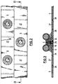
- an anchor pin (7) attached lining panels (5) arranged in rows overlapping. Between are two lining plates (5) attached to anchor pins (7) Intermediate plates (27) are provided, not on anchor pins, but thereby are held that they and the adjacent lining plates (5) stepped Have edges (28, 29), the stepped edges (29) of the Lining plates (5) the stepped edges (28) of the intermediate plates (27) overlap the combustion chamber (see Fig. 3). It is a single one Replacing defective lining plates (5) in a particularly simple way possible. To replace a destroyed lining plate (5), this is from their anchor pin (7) removed, for example broken down.
- Molded part (30) made of refractory ceramic material attached which is a special has low porosity, especially almost 0% porosity, and high strength owns.
- the molded part (30) can be fixed on the lining plate (5) by that it is in the manufacture of the lining plate (5) in the mass forming it is pressed in, a positive connection being produced via conical surfaces (31).
- the molded part (30) has a cavity (32) in which, following an opening (33) there is a rounded extension (34). According to this are the Projections (11,12) of the tongues (9,10) shaped.
- the lining plate (5) with its molded part (30) in the direction of the arrow (M) on the front slopes (15, 16) of the tongues (9, 10). This deform resiliently when passing through the opening (33) and then snap with their projections (11, 12) into the extension (34) of the Cavity (32).
- the tongues (9, 10) are found on the one hand on the bottom (35) of the Hollow (32) a stop and on the other hand find the rear bevels (17, 18) in the cavity (32) a stop.
- the lining plate (5) is thereby on Anchor pin (7) attached.
- the anchor pin (7) is in against the corrosive atmosphere of the combustion chamber (4) protected because it is opposite the combustion chamber (4) by the Lining plate (5) itself and covered by the molded part (30).
Abstract
Description
Die Erfindung betrifft eine Einrichtung zum Befestigen von Auskleidungsplatten aus feuerfestem keramischem Material an einer metallischen Wand, insbesondere für eine Müllverbrennungsanlage, wobei an der Wand metallische, geschlitzte Ankerstifte befestigt sind, die die Auskleidungsplatten tragen.The invention relates to a device for attaching lining panels refractory ceramic material on a metallic wall, especially for a waste incineration plant, with metallic, slotted on the wall Anchor pins are attached that support the liner panels.
Eine derartige Einrichtung ist in dem DE-GM 90 17 334 beschrieben. An die geschlitzten Ankerstifte lassen sich die Auskleidungsplatten nur ansetzen, solange die Ankerstifte noch nicht aufgespreizt sind. Nach dem Aufstecken der Auskleidungsplatten müssen die Ankerstifte mittels eines Werkzeugs aufgespreizt werden. Dies ist aufwendig. Es ist auch schwierig zu gewährleisten, daß alle Ankerstifte in gleicher Weise aufgespreizt werden. Bei einem ungleichmäßigen Aufspreizen der Ankerstifte können die Auskleidungsplatten Stöße bilden. Ein Auswechseln defekter Auskleidungsplatten ist kaum möglich, da hierfür die aufgespreizten Enden freigelegt und zusammengebogen werden müßten.Such a device is described in DE-GM 90 17 334. To the slotted anchor pins can only be attached to the lining panels as long as the anchor pins are not yet spread. After attaching the Lining plates must be spread open using a tool become. This is expensive. It is also difficult to ensure that everyone Anchor pins are spread in the same way. With an uneven Spreading out the anchor pins can form the lining plates. A It is hardly possible to replace defective cladding panels, as the Spread ends would have to be exposed and bent together.
Aufgabe der Erfindung ist es, eine Einrichtung der eingangs genannten Art vorzuschlagen, die das Anbringen der Auskleidungsplatten vereinfacht. The object of the invention is to provide a device of the type mentioned propose that simplifies the attachment of the lining panels.
Erfindungsgemäß ist obige Aufgabe bei einer Einrichtung der eingangs genannten Art dadurch gelöst, daß der Ankerstift wenigstens zwei federelastische Zungen bildet und daß an den Zungen radiale Vorsprünge gestaltet sind, die hinter einen mit der Auskleidungsplatte in Verbindung stehenden Anschlagrand druckknopfartig geschnappt sind.According to the invention, the above object is for a device of the type mentioned Art solved in that the anchor pin forms at least two resilient tongues and that radial projections are designed on the tongues, which behind one with the Lining plate in connection with the stop edge like a push button are snapped.
Das Anbringen der Auskleidungsplatten ist dadurch sehr einfach. Die Auskleidungsplatte wird mit einer den Anschlagrand bildenden Öffnung auf den Ankerstift gesteckt und dann angedrückt, wobei die radialen Vorsprünge der Zungen hinter den Anschlagrand formschlüssig schnappen. Die Zungen verschwenken sich dabei aufgrund ihrer Federelastizität. Es ist nicht notwendig, den Ankerstift mittels eines Werkzeugs aufzuspreizen. Da die Lage der Vorsprünge an den Zungen festliegt, ist gleichzeitig gewährleistet, daß die Auskleidungsplatten in der gewünschten Ausrichtung stehen.This makes it very easy to attach the lining panels. The Lining plate with an opening forming the stop edge on the Anchor pin inserted and then pressed, the radial projections of the tongues Snap positively behind the stop edge. The tongues swing due to their elasticity. It is not necessary to use the anchor pin spreading a tool. Because the location of the projections on the tongues is established, it is also ensured that the lining plates in the desired orientation.
Der Austausch einer defekten Auskleidungsplatte ist vergleichsweise einfach. Diese wird von dem Ankerstift abgenommen oder weggebrochen, wonach sich eine neue Auskleidungsplatte auf den freigelegten Ankerstift aufschnappen läßt.The replacement of a defective lining plate is comparatively easy. This is removed from the anchor pin or broken away, after which a new one Snap the lining plate onto the exposed anchor pin.
Zum Schutz des Ankerstifts vor dem korrosiven Angriff der Atmosphäre des Ofeninnenraums ist vorzugsweise auf die Enden der Zungen eine Kappe aus feuerfestem keramischem Material aufgesteckt, die in eine Isoliermasse eingebettet sein kann. Ein besonders sicherer Korrosionsschutz des Ankerstifts ist in bevorzugter Ausgestaltung der Erfindung dadurch erreicht, daß an der Auskleidungsplatte ein Formteil befestigt ist, das eine die Enden der Zungen aufnehmende und den Anschlagrand bildende Höhlung aufweist. Durch die Bemessung der Höhlung in Bezug auf die Zungen wird vorzugsweise gleichzeitig auch ein Tiefenanschlag für die Zungen erreicht, was die Lagensicherheit der Auskleidungsplatte weiter verbessert. To protect the anchor pin from the corrosive attack of the atmosphere of the Interior of the furnace is preferably a cap on the ends of the tongues fireproof ceramic material plugged into an insulating compound can be embedded. A particularly safe corrosion protection of the anchor pin is achieved in a preferred embodiment of the invention in that the Lining plate is attached to a molding, which is one the ends of the tongues has receiving and forming the stop edge. Through the Dimensioning of the cavity in relation to the tongues is preferably done simultaneously also reaches a depth stop for the tongues, which improves the position of the Lining panel further improved.
Weitere vorteilhafte Ausgestaltungen der Erfindung ergeben sich aus den
Unteransprüchen und der folgenden Beschreibung von Ausführungsbeispielen. In
der Zeichnung zeigen:
Ein Verbrennungsofen, beispielsweise einer Müllverbrennungsanlage, weist eine
metallische Rohrwand (1) mit wasserführenden Röhren(2) und diese verbindenden
Stegen(3) bzw. Flossen auf Zur Verbrennungskammer(4) hin sind an der
Rohrwand(1) Auskleidungsplatten(5) aus feuerfestem keramischem Material,
insbesondere SiC-Material, angeordnet. Die Oberfläche der Auskleidungsplatte 5
kann gewellt sein. Zwischen diesen und der Rohrwand(1) ist eine Isolier- und
Ausgleichslage(6), beispielsweise aus keramischem Fasermaterial, angeordnet.
An einen der Stege(3) sind verteilt Ankerstifte(7) aus Metall, beispielsweise
Federstahl, angeschweißt. Der Ankerstift(7) hat einen runden oder rechteckigen
Querschnitt. Er weist einen Längsschlitz(8) auf, neben dem federelastische
Zungen(9,10) bestehen. Der Ankerstift (7) kann auch zwei- oder mehrfach geschlitzt
sein, wobei entsprechend mehr federelastische Zungen bestehen.A combustion furnace, for example a waste incineration plant, has one
metallic tube wall (1) with water-carrying tubes (2) and connecting them
Web (3) or fins on to the combustion chamber (4) are on the
Pipe wall (1) lining plates (5) made of refractory ceramic material,
in particular SiC material. The surface of the
An den Zungen(9,10) sind bezogen auf die Längsachse des Ankerstifts(7) radiale Vorsprünge(11,12) gestaltet. Diese bilden anschließend an Enden(13,14) vordere Schrägen(15, 16), die in hintere Schrägen(17,18) übergehen. Die Auskleidungsplatte(5) weist eine konische Vertiefung (19) auf, deren der Rohrwand(1) zugewandte kleinere Öffnung einen Anschlagrand(20) bildet. On the tongues (9,10) are radial with respect to the longitudinal axis of the anchor pin (7) Projections (11,12) designed. These then form front ends (13, 14) Slopes (15, 16) which merge into rear slants (17, 18). The Lining plate (5) has a conical recess (19), the Pipe wall (1) facing smaller opening forms a stop edge (20).
Die Montage der Auskleidungsplatte(5) an dem an der Rohrwand(1) befestigten Ankerstift(7) geschieht etwa folgendermaßen:Assemble the lining plate (5) to the one attached to the pipe wall (1) Anchor pin (7) happens approximately as follows:
Die Auskleidungsplatte(5) wird mit ihrer den Anschlagrand (20) bildenden Öffnung auf die Enden(13,14) des Ankerstifts(7) in Richtung des Pfeiles(M) aufgesteckt, wobei die Enden(13,14) zwanglos in die Öffnung passen. Zur Erleichterung dieses Aufsteckens kann die Öffnung anschließend an den Anschlagrand(20) mit einer Einführschräge(21) versehen sein. Danach wird dann in Richtung des Pfeiles(M) ein Druck auf die Auskleidungsplatte(5) ausgeübt. Dabei gleitet unter federelastischer Verformung der Zungen(9,10) der Anschlagrand(20) an den vorderen Schrägen (15,16). Wenn er die vorderen Schrägen(15,16) überwunden hat, gleitet er an den hinteren Schrägen(17,18) weiter, wobei die Zungen (9,10) federelastisch aufschnappen. Die Auskleidungsplatte(5) ist nun in der in Figur 1 dargestellten Position gehalten. Um ein flächiges Anliegen des Anschlagrandes(20) an den hinteren Schrägen (17,18) zu erreichen, kann der Winkel der hinteren Schrägen (17,18) dem Winkel der konischen Vertiefung(19) gleich sein.The lining plate (5) with its opening forming the stop edge (20) put on the ends (13, 14) of the anchor pin (7) in the direction of the arrow (M), the ends (13, 14) easily fitting into the opening. To make this easier The opening can then be attached to the stop edge (20) with a Insertion bevel (21) may be provided. Then it is in the direction of arrow (M) Pressure is exerted on the lining plate (5). It slides under spring elastic Deformation of the tongues (9, 10) of the stop edge (20) on the front slopes (15.16). When he has overcome the front slopes (15, 16), he glides to the rear bevels (17,18) further, the tongues (9,10) resilient snap open. The lining plate (5) is now shown in FIG. 1 Position held. In order for the stop edge (20) to lie flat against the To achieve rear slopes (17, 18), the angle of the rear slopes (17, 18) the angle of the conical recess (19).
Um einen Einrasteffekt zu verbessern, ist es möglich, in Richtung der Rohrwand(1) anschließend an die hinteren Schrägen(17,18) an den Stellen(22) Vertiefungen vorzusehen, welche in eine Kante(23) des Anschlagrandes (20) rasten.In order to improve a snap-in effect, it is possible in the direction of the pipe wall (1) then to the rear bevels (17, 18) at the points (22) depressions to provide, which snap into an edge (23) of the stop edge (20).
Bei der Ausführung nach Figur 1 überragen die Vorsprünge (11,12) den dem Steg(3)
nahen Querschnitt des Ankerstifts (7) radial. Dies ist jedoch nicht erforderlich. Der
dem Steg(3) nahe Querschnitt des Ankerstifts(7) kann auch ebenso groß oder
größer sein wie der Querschnitt in dem Bereich, in dem die vorderen
Schrägen(15,16) in die
hinteren Schrägen(17,18) übergehen.In the embodiment according to FIG. 1, the projections (11, 12) project radially beyond the cross section of the anchor pin (7) close to the web (3). However, this is not necessary. The cross section of the anchor pin (7) close to the web (3) can also be as large or larger than the cross section in the area in which the front bevels (15, 16) into the
pass over the rear slopes (17, 18).
Nach dem Aufschnappen der Auskleidungsplatte(5) auf den Ankerstift(7) wird in die konische Vertiefung(19)eine Isoliermasse(24) eingebracht und auf die Enden(13,14) der Zungen(9,10) wird eine Kappe(25) aus feuerfestem keramischem Material, insbesondere SiC-Material, aufgesetzt, die so bemessen ist, daß sie innerhalb derAfter snapping the lining plate (5) onto the anchor pin (7) is in the conical recess (19) an insulating compound (24) and placed on the ends (13, 14) the tongues (9, 10) become a cap (25) made of refractory ceramic material, in particular SiC material, which is dimensioned so that it is within the
Vertiefung(19) fluchtend mit der Oberfläche(5.1) der Auskleidungsplatte(5) steht. Zur gleichmäßigen Verteilung der Isoliermasse(24) kann an der Kappe(25) eine Ausgleichsbohrung(26) vorgesehen sein. Durch die in der Isoliermasse(24) sitzende Kappe(25) ist der Ankerstift(7) gegen die in der Verbrennungskammer(4) herrschende korrosive Atmosphäre und gegen die dort herrschenden Temperaturen, beispielsweise etwa 1200°C, geschützt.Recess (19) is aligned with the surface (5.1) of the lining plate (5). For uniform distribution of the insulating material (24) on the cap (25) Compensating bore (26) may be provided. Through the seated in the insulating compound (24) Cap (25) is the anchor pin (7) against that in the combustion chamber (4) prevailing corrosive atmosphere and against the temperatures prevailing there, protected, for example, about 1200 ° C.
Im Wandaufbau nach den Figuren 2 und 3 sind jeweils mittels eines Ankerstiftes(7) befestigte Auskleidungsplatten(5) in Reihen überlappend angeordnet. Zwischen jeweils zwei an Ankerstiften(7) befestigten Auskleidungsplatten(5) sind Zwischenplatten(27) vorgesehen, die nicht an Ankerstiften, sondern dadurch gehalten sind, daß sie und die angrenzenden Auskleidungsplatten(5) gestufte Ränder(28,29) aufweisen, wobei die gestuften Ränder(29) der Auskleidungsplatten(5) die gestuften Ränder(28) der Zwischenplatten(27) verbrennungskammerseitig übergreifen (vgl. Fig.3). Es ist damit ein einzelnen Auswechseln defekter Auskleidungsplatten(5) auf besondere einfache Weise möglich. Zum Auswechseln einer zerstörten Auskleidungsplatte(5) wird diese von ihrem Ankerstift(7) entfernt, beispielsweise runtergebrochen. Anschließend wird, wie oben beschrieben, eine neue Auskleidungsplatte auf den Ankerstift(7) aufgeschnappt, wobei ihre Ränder (29) die Ränder(28) benachbarter Zwischenplatten(27) wieder übergreifen. Anschließend wird in die Vertiefung (19) Isoliermasse(24) eingebracht und eine Kappe(25) wird aufgedrückt.In the wall structure according to FIGS. 2 and 3, an anchor pin (7) attached lining panels (5) arranged in rows overlapping. Between are two lining plates (5) attached to anchor pins (7) Intermediate plates (27) are provided, not on anchor pins, but thereby are held that they and the adjacent lining plates (5) stepped Have edges (28, 29), the stepped edges (29) of the Lining plates (5) the stepped edges (28) of the intermediate plates (27) overlap the combustion chamber (see Fig. 3). It is a single one Replacing defective lining plates (5) in a particularly simple way possible. To replace a destroyed lining plate (5), this is from their anchor pin (7) removed, for example broken down. Then how described above, a new lining plate on the anchor pin (7) snapped with their edges (29) the edges (28) adjacent Reach over intermediate plates (27) again. Then the recess (19) Insulating compound (24) is introduced and a cap (25) is pressed on.
Beim Ausführungsbeispiel nach Figur 4 ist an der Auskleidungsplatte(5) ein Formteil(30) aus feuerfestem keramischem Material befestigt, das eine besonders geringe Porosität, insbesondere fast 0%-Porosität, aufweist und eine hohe Festigkeit besitzt. Das Formteil (30) läßt sich an der Auskleidungsplatte(5) dadurch festlegen, daß es bei der Herstellung der Auskleidungsplatte(5) in die sie bildende Masse eingepreßt wird, wobei über konische Flächen(31) ein Formschluß entsteht. In the exemplary embodiment according to FIG. 4 there is a on the lining plate (5) Molded part (30) made of refractory ceramic material attached, which is a special has low porosity, especially almost 0% porosity, and high strength owns. The molded part (30) can be fixed on the lining plate (5) by that it is in the manufacture of the lining plate (5) in the mass forming it is pressed in, a positive connection being produced via conical surfaces (31).
Das Formteil(30) weist eine Höhlung(32) auf, in der im Anschluß an eine Öffnung(33) eine ausgerundete Erweiterung(34) besteht. Dieser entsprechend sind die Vorsprünge(11,12) der Zungen(9,10) geformt. Der Querschnitt - senkrecht zur Zeichenebene der Figur 4 - des Formteils(30) und/oder der Höhlung(32), und entsprechend der Zungen(9,10) kann rund oder längsgestreckt bzw. langlochartig sein, was die Stabilität erhöht.The molded part (30) has a cavity (32) in which, following an opening (33) there is a rounded extension (34). According to this are the Projections (11,12) of the tongues (9,10) shaped. The cross section - perpendicular to Drawing level of Figure 4 - the molded part (30) and / or the cavity (32), and According to the tongues (9,10) can be round or elongated or elongated be what increases stability.
Bei der Montage wird die Auskleidungsplatte(5) mit ihrem Formteil(30) in Richtung des Pfeiles(M) auf die vorderen Schrägen(15,16) der Zungen(9, 10) gedrückt. Diese verformen sich dabei bei Durchtritt durch die Öffnung(33) federelastisch und schnappen dann mit ihren Vorsprüngen (11,12) in die Erweiterung(34) der Höhlung(32) ein. Die Zungen(9,10) finden dabei einerseits am Boden(35) der Höhlung(32) einen Anschlag und andererseits finden die hinteren Schrägen(17,18) in der Höhlung(32) einen Anschlag. Die Auskleidungsplatte(5) ist dadurch am Ankerstift(7) befestigt. Bei der Ausführung nach Figur 4 ist der Ankerstift(7) in besonderer Weise gegen die korrosive Atmosphäre der Verbrennungskammer(4) geschützt, weil er gegenüber der Verbrennungskammer(4) durch die Auskleidungsplatte(5) selbst und durch das Formteil(30) abgedeckt ist.During assembly, the lining plate (5) with its molded part (30) in the direction of the arrow (M) on the front slopes (15, 16) of the tongues (9, 10). This deform resiliently when passing through the opening (33) and then snap with their projections (11, 12) into the extension (34) of the Cavity (32). The tongues (9, 10) are found on the one hand on the bottom (35) of the Hollow (32) a stop and on the other hand find the rear bevels (17, 18) in the cavity (32) a stop. The lining plate (5) is thereby on Anchor pin (7) attached. In the embodiment according to FIG. 4, the anchor pin (7) is in against the corrosive atmosphere of the combustion chamber (4) protected because it is opposite the combustion chamber (4) by the Lining plate (5) itself and covered by the molded part (30).
Bei langlochartiger Gestaltung der Höhlung läßt sich ein gewisser Toleranzausgleich im Plattenverbund erreichen.With a slot-like design of the cavity, a certain tolerance compensation can be made reach in the composite.
Claims (11)
dadurch gekennzeichnet,
daß der Ankerstift (7) wenigstens zwei federelastische Zungen (9,10) bildet und daß an den Zungen (9,10) radiale Vorsprünge (11,12) gestaltet sind, die hinter einen mit der Auskleidungsplatte (5) in Verbindung stehenden Anschlagrand (20) druckknopfartig geschnappt sind.Device for fastening liner plates made of refractory ceramic material to a metallic wall, in particular a waste incineration plant, wherein metallic, slotted anchor pins are attached to the wall, which carry the liner plates,
characterized,
that the anchor pin (7) forms at least two resilient tongues (9, 10) and that radial projections (11, 12) are formed on the tongues (9, 10), which protrude behind a stop edge (5) connected to the lining plate (5) 20) are snapped like a button.
dadurch gekennzeichnet,
daß die Vorsprünge (11,12) vordere Schrägen (15,16) bilden, die unter federelastischem Verschwenken der Zungen (9,10) in eine den Anschlagrand (20) bildende Öffnung der Auskleidungsplatte (5) einschiebbar sind.Device according to claim 1,
characterized,
that the projections (11, 12) form front bevels (15, 16) which can be inserted into an opening of the lining plate (5) forming the stop edge (20) while the tongues (9, 10) are pivoted elastically.
dadurch gekennzeichnet,
daß die Vorsprünge (11,12) hintere Schrägen (17,18) bilden, die an den Anschlagrand (20) geschnappt sind. Device according to claim 1 or 2,
characterized,
that the projections (11, 12) form rear bevels (17, 18) which are snapped onto the stop edge (20).
dadurch gekennzeichnet,
daß auf die Enden (13,14) der Zungen (9,10) eine Kappe (25) aus feuerfestem keramischem Material aufgesetzt ist.Device according to one of the preceding claims,
characterized,
that a cap (25) made of refractory ceramic material is placed on the ends (13, 14) of the tongues (9, 10).
dadurch gekennzeichnet,
daß die Kappe (25) in einer konischen, den Anschlagrand (20) bildenden Vertiefung (19) der Auskleidungsplatte (5) liegt.Device according to claim 4,
characterized,
that the cap (25) in a conical, the stop edge (20) forming recess (19) of the lining plate (5).
dadurch gekennzeichnet,
daß die Kappe (25) mittels Isoliermasse (24) in der Vertiefung (19) eingebettet ist.Device according to claim 5,
characterized,
that the cap (25) is embedded in the recess (19) by means of insulating compound (24).
dadurch gekennzeichnet,
daß an der Auskleidungsplatte (5) ein Formteil (30) befestigt ist, das eine die Vorsprünge (11,12) der Zungen (9,10) aufnehmende und den Anschlagrand (20) bildende Höhlung (32) aufweist.Device according to one of the preceding claims 1 to 3,
characterized,
that a molded part (30) is fastened to the lining plate (5) and has a cavity (32) which receives the projections (11, 12) of the tongues (9, 10) and forms the stop edge (20).
dadurch gekennzeichnet,
daß das keramische Formteil (30) eine Porosität von etwa 0% aufweist.Device according to claim 7,
characterized,
that the ceramic molding (30) has a porosity of about 0%.
dadurch gekennzeichnet,
daß die Höhlung (32) mit ihrem Boden (35) einen Tiefenanschlag für die Zungen (9,10) bildet. Device according to one of the preceding claims 6 to 8,
characterized,
that the cavity (32) with its bottom (35) forms a depth stop for the tongues (9, 10).
dadurch gekennzeichnet,
daß der Anschlagrand (20) und/oder die an diesen geschnappten Vorsprüge (11,12) einen runden oder rechteckigen Querschnitt bilden.Device according to one of the preceding claims,
characterized,
that the stop edge (20) and / or the snaps (11, 12) snapped onto them form a round or rectangular cross section.
dadurch gekennzeichnet,
daß der Ankerstift (7) wenigstens eine Vertiefung (22) aufweist, in die der Anschlagrand (20) einrastet.Device according to one of the preceding claims,
characterized,
that the anchor pin (7) has at least one recess (22) into which the stop edge (20) engages.
Applications Claiming Priority (2)
| Application Number | Priority Date | Filing Date | Title |
|---|---|---|---|
| DE19825546 | 1998-06-08 | ||
| DE19825546A DE19825546C1 (en) | 1998-06-08 | 1998-06-08 | Device for fixing cladding plates of fireproof ceramic material to metal wall |
Publications (2)
| Publication Number | Publication Date |
|---|---|
| EP0964205A2 true EP0964205A2 (en) | 1999-12-15 |
| EP0964205A3 EP0964205A3 (en) | 2000-11-02 |
Family
ID=7870277
Family Applications (1)
| Application Number | Title | Priority Date | Filing Date |
|---|---|---|---|
| EP99110737A Withdrawn EP0964205A3 (en) | 1998-06-08 | 1999-06-04 | Device for fastening lining plates |
Country Status (3)
| Country | Link |
|---|---|
| EP (1) | EP0964205A3 (en) |
| CN (1) | CN1239764A (en) |
| DE (1) | DE19825546C1 (en) |
Cited By (3)
| Publication number | Priority date | Publication date | Assignee | Title |
|---|---|---|---|---|
| US6837015B2 (en) | 2001-11-14 | 2005-01-04 | Mitsubishi Heavy Industries, Ltd. | Installation method of fireproof structure for protecting water pipes |
| SG109991A1 (en) * | 2001-11-08 | 2005-04-28 | Mitsubishi Heavy Ind Ltd | Fireproof structure and installation method for protecting water pipes |
| EP1701122A2 (en) * | 2005-03-11 | 2006-09-13 | Plibrico G.m.b.H. | Heat shield element and method for manufacturing the same |
Families Citing this family (7)
| Publication number | Priority date | Publication date | Assignee | Title |
|---|---|---|---|---|
| EP0962696A4 (en) * | 1997-11-28 | 2002-03-06 | Mitsubishi Heavy Ind Ltd | Water tube protective refractory structure and method of assembling the same |
| EP1236954A1 (en) * | 2001-03-02 | 2002-09-04 | Karrena GmbH | Plates on boiler tube walls |
| FR2840672B1 (en) * | 2002-06-07 | 2004-12-24 | Lafarge Refractories | SYSTEM FOR HANGING NON-SHAPED REFRACTORY MATERIAL ON A TUBULAR WALL OF A BOILER |
| EP2236928A1 (en) * | 2009-03-17 | 2010-10-06 | Siemens Aktiengesellschaft | Heat shield element |
| EP3117147B1 (en) * | 2014-03-03 | 2019-01-16 | Ansaldo Energia S.p.A. | Combustion chamber of a gas turbine assembly |
| DE102018200926A1 (en) * | 2018-01-22 | 2019-07-25 | Siemens Aktiengesellschaft | Component for positioning a heat shield element |
| CN110985818A (en) * | 2019-11-27 | 2020-04-10 | 广东省工业设备安装有限公司 | Reinforcing nail and reinforcing method for integrated composite air pipe |
Citations (5)
| Publication number | Priority date | Publication date | Assignee | Title |
|---|---|---|---|---|
| DE566927C (en) * | 1930-11-18 | 1932-12-24 | Franz Hof | Firebox ceiling |
| US2413425A (en) * | 1944-09-07 | 1946-12-31 | Plibrico Jointless Firebrick C | Anchor extension means |
| GB2233079A (en) * | 1989-06-05 | 1991-01-02 | Williamson Cliff Limited | Refractory lining of furnaces |
| DE9017334U1 (en) * | 1990-12-20 | 1991-03-07 | K + K Ofenbau Gmbh, 4040 Neuss, De | |
| GB2265411A (en) * | 1992-03-26 | 1993-09-29 | Swintex | Quick release toggle; barrier system |
Family Cites Families (3)
| Publication number | Priority date | Publication date | Assignee | Title |
|---|---|---|---|---|
| DE1173734B (en) * | 1962-10-11 | 1964-07-09 | Siemens Ag | Combustion chamber, especially for gas turbines, with a lining made of refractory bricks |
| DE19502730A1 (en) * | 1995-01-28 | 1996-08-01 | Abb Management Ag | Ceramic lining |
| DE19611532C1 (en) * | 1996-03-23 | 1997-06-12 | Didier Werke Ag | Fire room wall in refuse incinerator plants |
-
1998
- 1998-06-08 DE DE19825546A patent/DE19825546C1/en not_active Expired - Fee Related
-
1999
- 1999-06-04 EP EP99110737A patent/EP0964205A3/en not_active Withdrawn
- 1999-06-08 CN CN 99108326 patent/CN1239764A/en active Pending
Patent Citations (5)
| Publication number | Priority date | Publication date | Assignee | Title |
|---|---|---|---|---|
| DE566927C (en) * | 1930-11-18 | 1932-12-24 | Franz Hof | Firebox ceiling |
| US2413425A (en) * | 1944-09-07 | 1946-12-31 | Plibrico Jointless Firebrick C | Anchor extension means |
| GB2233079A (en) * | 1989-06-05 | 1991-01-02 | Williamson Cliff Limited | Refractory lining of furnaces |
| DE9017334U1 (en) * | 1990-12-20 | 1991-03-07 | K + K Ofenbau Gmbh, 4040 Neuss, De | |
| GB2265411A (en) * | 1992-03-26 | 1993-09-29 | Swintex | Quick release toggle; barrier system |
Cited By (6)
| Publication number | Priority date | Publication date | Assignee | Title |
|---|---|---|---|---|
| SG109991A1 (en) * | 2001-11-08 | 2005-04-28 | Mitsubishi Heavy Ind Ltd | Fireproof structure and installation method for protecting water pipes |
| US7204061B2 (en) | 2001-11-08 | 2007-04-17 | Mitsubishi Heavy Industries, Ltd. | Fireproof structure and installation method for protecting water pipes |
| US6837015B2 (en) | 2001-11-14 | 2005-01-04 | Mitsubishi Heavy Industries, Ltd. | Installation method of fireproof structure for protecting water pipes |
| SG109999A1 (en) * | 2001-11-14 | 2005-04-28 | Mitsubishi Heavy Ind Ltd | Installation method of fireproof structure for protecting water pipes |
| EP1701122A2 (en) * | 2005-03-11 | 2006-09-13 | Plibrico G.m.b.H. | Heat shield element and method for manufacturing the same |
| EP1701122A3 (en) * | 2005-03-11 | 2006-12-06 | Plibrico G.m.b.H. | Heat shield element and method for manufacturing the same |
Also Published As
| Publication number | Publication date |
|---|---|
| EP0964205A3 (en) | 2000-11-02 |
| DE19825546C1 (en) | 1999-08-26 |
| CN1239764A (en) | 1999-12-29 |
Similar Documents
| Publication | Publication Date | Title |
|---|---|---|
| DE2718170C3 (en) | Fastening clips for covered cover plates, in particular for motor vehicles | |
| DE3339441C2 (en) | Slide valve | |
| DE19825546C1 (en) | Device for fixing cladding plates of fireproof ceramic material to metal wall | |
| EP1211137B1 (en) | Connecting element | |
| EP0437444B1 (en) | Magazine for firearm | |
| DE10231203A1 (en) | Target support assembly | |
| DE2309398B2 (en) | Arrangement for the axial support of a constant velocity joint | |
| DE102013106975A1 (en) | spacer | |
| EP0287973B1 (en) | Façade covering ventilated from the rear | |
| EP1876314A2 (en) | Mounting element | |
| EP0280107A1 (en) | Water-air cooler | |
| EP3112554A1 (en) | Terrace system and holder for fastening view profiles | |
| EP0479011B1 (en) | Fan cover for fastening on the radiator of an internal combustion engine | |
| EP0939270A1 (en) | Jet pipe device | |
| WO2006077223A1 (en) | Connecting device for media pipes | |
| DE3415370A1 (en) | Air blow-out nozzle of an installation for room ventilation | |
| EP2055856A2 (en) | Roof design | |
| EP0963496A1 (en) | Facade fixing device | |
| WO2022248412A1 (en) | Retaining device for retaining a ceramic anchor brick on a furnace wall, furnace comprising a retaining device of this type, and method for fastening a retaining device of this type to a furnace wall | |
| DE7710598U1 (en) | Electric light bulb socket | |
| DE10137842A1 (en) | Component for inclusion in a body part, in particular light | |
| DE3831051C2 (en) | Flat gasket | |
| DE19815178C1 (en) | Device for fixing fiber block to furnace wall | |
| DE102009039390A1 (en) | Corrosion protection body | |
| DE102019219845A1 (en) | Heat shield tile for a combustion chamber and combustion chamber |
Legal Events
| Date | Code | Title | Description |
|---|---|---|---|
| PUAI | Public reference made under article 153(3) epc to a published international application that has entered the european phase |
Free format text: ORIGINAL CODE: 0009012 |
|
| AK | Designated contracting states |
Kind code of ref document: A2 Designated state(s): AT BE CH CY DE DK ES FI FR GB GR IE IT LI LU MC NL PT SE |
|
| AX | Request for extension of the european patent |
Free format text: AL;LT;LV;MK;RO;SI |
|
| PUAL | Search report despatched |
Free format text: ORIGINAL CODE: 0009013 |
|
| AK | Designated contracting states |
Kind code of ref document: A3 Designated state(s): AT BE CH CY DE DK ES FI FR GB GR IE IT LI LU MC NL PT SE |
|
| AX | Request for extension of the european patent |
Free format text: AL;LT;LV;MK;RO;SI |
|
| AKX | Designation fees paid | ||
| STAA | Information on the status of an ep patent application or granted ep patent |
Free format text: STATUS: THE APPLICATION IS DEEMED TO BE WITHDRAWN |
|
| 18D | Application deemed to be withdrawn |
Effective date: 20010503 |
|
| REG | Reference to a national code |
Ref country code: DE Ref legal event code: 8566 |