EP0962846A1 - Vorrichtung zur Steuerung eines Durchflusses - Google Patents
Vorrichtung zur Steuerung eines Durchflusses Download PDFInfo
- Publication number
- EP0962846A1 EP0962846A1 EP98123912A EP98123912A EP0962846A1 EP 0962846 A1 EP0962846 A1 EP 0962846A1 EP 98123912 A EP98123912 A EP 98123912A EP 98123912 A EP98123912 A EP 98123912A EP 0962846 A1 EP0962846 A1 EP 0962846A1
- Authority
- EP
- European Patent Office
- Prior art keywords
- flow rate
- flow control
- pump
- pipe line
- main pipe
- Prior art date
- Legal status (The legal status is an assumption and is not a legal conclusion. Google has not performed a legal analysis and makes no representation as to the accuracy of the status listed.)
- Granted
Links
Images


Classifications
-
- G—PHYSICS
- G05—CONTROLLING; REGULATING
- G05D—SYSTEMS FOR CONTROLLING OR REGULATING NON-ELECTRIC VARIABLES
- G05D7/00—Control of flow
- G05D7/06—Control of flow characterised by the use of electric means
- G05D7/0617—Control of flow characterised by the use of electric means specially adapted for fluid materials
- G05D7/0629—Control of flow characterised by the use of electric means specially adapted for fluid materials characterised by the type of regulator means
- G05D7/0688—Control of flow characterised by the use of electric means specially adapted for fluid materials characterised by the type of regulator means by combined action on throttling means and flow sources
-
- Y—GENERAL TAGGING OF NEW TECHNOLOGICAL DEVELOPMENTS; GENERAL TAGGING OF CROSS-SECTIONAL TECHNOLOGIES SPANNING OVER SEVERAL SECTIONS OF THE IPC; TECHNICAL SUBJECTS COVERED BY FORMER USPC CROSS-REFERENCE ART COLLECTIONS [XRACs] AND DIGESTS
- Y10—TECHNICAL SUBJECTS COVERED BY FORMER USPC
- Y10T—TECHNICAL SUBJECTS COVERED BY FORMER US CLASSIFICATION
- Y10T137/00—Fluid handling
- Y10T137/7722—Line condition change responsive valves
- Y10T137/7758—Pilot or servo controlled
- Y10T137/7759—Responsive to change in rate of fluid flow
-
- Y—GENERAL TAGGING OF NEW TECHNOLOGICAL DEVELOPMENTS; GENERAL TAGGING OF CROSS-SECTIONAL TECHNOLOGIES SPANNING OVER SEVERAL SECTIONS OF THE IPC; TECHNICAL SUBJECTS COVERED BY FORMER USPC CROSS-REFERENCE ART COLLECTIONS [XRACs] AND DIGESTS
- Y10—TECHNICAL SUBJECTS COVERED BY FORMER USPC
- Y10T—TECHNICAL SUBJECTS COVERED BY FORMER US CLASSIFICATION
- Y10T137/00—Fluid handling
- Y10T137/8593—Systems
- Y10T137/87265—Dividing into parallel flow paths with recombining
- Y10T137/87338—Flow passage with bypass
- Y10T137/87354—Including flowmeter
Definitions
- This invention relates to a flow control device which can control the flow rate of fluid over a wide flow rate range.
- An object of this invention is to provide a flow control device which can control the flow rate with extremely high accuracy over a wide flow rate range with a single pump.
- a flow control device comprising: a main pipe line having an inlet port through which fluid is introduced into the main pipe line, and a discharge port; a pump provided in the main pipe line and having a predetermined discharge flow rate range; a flowmeter provided in the main pipe line between the pump and the discharge port; and a flow control valve provided in the main pipe line between the pump and the discharge port; the flow control valve having a control flow rate range including a flow rate range lower than the predetermined discharge flow rate range of the pump; whereby the degree of opening of the flow control valve is adjusted based on flow rate data from the flowmeter.
- a flow control device comprising a main pipe line having an inlet port through which fluid is introduced into the main pipe line, and a discahrge port; a bypass pipe line branching from the main pipe line at a first point and merging with the main pipe line at a second point disposed between the first point and the discharge port; a pump provided in the main pipe line between the inlet port and the first point and having a predetermined discharge flow rate range; a changeover valve provided in the main pipe line at the first point; a first flowmeter provided in the main pipe line between the pump and the discharge port; a second flowmeter and a flow control valve provided in the bypass line; the flow control valve having a control flow rate range including a flow rate range lower than the predetermined discharge flow rate range of the pump; and a flow control unit for operating the changeover valve to feed fluid into the bypass line and adjusting the degree of opening of the flow control valve based on flow rate data from the second flowmeter if the fluid is to be fed at a flow rate
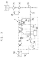
- the device shown includes a pump 2, a bypass flowmeter 3, a flow control valve 4, pipe lines 5, a main pipe back pressure regulating valve 8a, and a bypass back pressure regulating valve 8b.
- the pipe lines 5 comprise a main line 5a, a bypass 5b and a return line 5c.
- the main line 5a has an inlet port 10 at one end through which fluid enters, and a discharge port 11 at the other end.
- the pump 2 is provided near the inlet 10 of the main line 5a.
- a variable-volume pump is preferable because it is high in discharge ratio and accurate.
- a gear pump is the most preferable.
- the device 1 further includes a main line flowmeter 6 between the pump 2 and the discharge port 11.
- the flowmeter 6 is preferably an electromagnetic flowmeter because it is high in range ability and accurate.
- the flow rate detected by the flowmeter 6 is inputted into a controller 20, which based on the detected value, adjusts the discharge rate from the pump 2.
- the main line flowmeter 6 is not an essential element but a desirable option for higher accuracy of flow control.
- the bypass 5b branches from the main line 5 at a point between the main line flowmeter 6 and the discharge port 11. At the branch point, a changeover valve 12 is provided.
- the bypass 5b merges with the main line 5a at a point immediately upstream of the discharge port 11.
- the controller 20 controls the changeover valve 12 to selectively direct fluid introduced into the main line 5a through the pump 2, into the bypass 5b or through the main line 5a.
- bypass flowmeter 3 and the flow control valve 4 are provided in the bypass 5b.
- the bypass back pressure regulating valve 8b is also provided in the bypass at a point near the discharge port 11.
- bypass flowmeter 3 an electromagnetic flowmeter is preferable because it is high in range ability and accurate.
- the flow rate detected by this flowmeter 3 is entered into the controller 20, which, based on the detected value, adjusts the degree of opening of the flow control valve 4.
- the flow control valve 4 should be such that can control the flow rate within the range that is lower than the discharge flow rate range controllable by the pump 2.
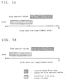
- the flow control ranges of the pump 2 and the valve 4 should be determined such that the flow control ranges by the valve 4 and the pump 2 overlap with each other, as shown in Fig. 5A, or the upper limit of the flow range controllable by the valve 4 substantially coincides with the lower limit of the flow range controllable by the pump 2 as shown in Fig. 5B.
- the flow ranges controllable by the pump 2 and the valve 4 may overlap with each other over a wider area than the area shown in Fig. 5A. But the wider the overlap, the narrower the range within which the flow rate is controllable with high accuracy.
- the bypass back pressure regulating valve 8b may be any valve which can suppress pressure fluctuation at the discharge end of the flow control valve 4.
- it may be a back pressure regulating valve (BV-F10SE made by Tacmina, pressure regulating range 0.5-2.5 kgf/cm 2 ), an upstream pressure regulating valve (GD-20R made by Yoshitake, pressure regulating range 0.5-2.5 kgf/cm 2 , or a back pressure regulating valve (RPD 52-2 made by Fushiman, pressure regulating range 0.7-2.0 kgf/cm 2 ).
- BV-F10SE back pressure regulating valve
- GD-20R upstream pressure regulating valve
- RPD 52-2 back pressure regulating valve
- the return line 5c connects a point of the bypass 5b nearer to the inlet 10 than is the flowmeter 3 with a point of the main line 5a nearer to the inlet 10 than is the pump 2. Any excess fluid resulting from flow control by the flow control valve 4 while fluid is being fed through the bypass 5b is directed into the return line 5c and merged into fluid being fed from the inlet 10 at a point nearer to the inlet 10 than is the pump 2. Excess fluid is returned into the main line 5a. This prevents waste of fluid.
- the controller 20 selectively opens and closes the return line 5c by controlling a needle valve 13. In order to feed fluid only through the main line 5a, the controller 20 closes the needle valve 13 to prevent fluid in the main line 5a from flowing into the return line 5c.
- the flow control device 1 is used to control the flow rate in the following manner. First, a desired flow rate or a flow rate setting program is entered into the controller 20. The controller 20 determines if the desired flow rate entered is within a high flow rate range controllable by the pump 2 only or within a low flow rate range controllable by the cooperation of the pump 2 and the flow control valve 4. In the former case, the controller 20 controls the changeover valve 12 to feed fluid through the main line 5a. In the latter case, the controller controls the changeover valve 12 to direct fluid into the bypass line 5b.
- Fig. 2A shows the flow path when fluid is fed at a high rate.
- the controller 20 controls the changeover valve 12 to open the main line 5a and closes the needle valve 13 in the return line 5c. Fluid sucked in through the inlet 10 by the pump 2 flows through the main line 5a and is discharged through the discharge port 11. At this time, the flow rate of the fluid fed by the pump 2 is continuously monitored by the main line flowmeter 6. If the monitored flow rate is out of a predetermined range, the controller 20 produces a signal to adjust the degree of opening of the pump 2. Fluid can thus be fed at a higher rate with high accuracy. Since the main line back pressure regulating valve 8a provided near the discharge port 11 suppresses pressure fluctuation on the discharge side of the main line 5a, the flow rate can be controlled even more accurately.
- Fig. 2B shows a flow path when fluid is to be fed at a low rate.
- the controller 20 controls the changeover valve 12 to direct fluid into the bypass 5b and fully opens the needle valve 13 in the return line 5c.
- the controller 20 further controls the degree of opening of the pump 2 so that fluid flows at a minimum or a low rate within an accurately controllable range. It also controls the flow control valve 4 so that fluid will be discharged at a predetermined flow rate.
- fluid sucked in through the inlet port 10 by the pump 2 flows through the main line 5a, and is directed by the changeover valve 12 into the bypass 5b as shown in Fig. 2B.
- fluid passes through the flow control valve 4, where its flow rate is controlled, and a bypass back pressure regulating valve 8b and is discharged through the discharge port 11.
- the flow rate of the fluid flowing through the bypass 5b is continuously monitored by the bypass flowmeter 3. If the monitored flow rate is out of a predetermined flow rate range, the controller 20 produces a signal to control the degree of opening of the flow control valve 4. Fluid can thus be fed at a low rate with high accuracy. Since the bypass back pressure regulating valve 8b provided nearer to the outlet port 11 than are the bypass flowmeter 3 and the flow control valve 4 suppresses pressure fluctuation on the discharge side of the flow control valve 4, fluid flow can be controlled with even higher accuracy. In the embodiment, the bypass back pressure regulating valve 8b is provided in the bypass 5b, that is, no pipe branches from the portion of the line between the flow control valve 4 and the bypass back pressure regulating valve 8b. Thus, it is possible to more reliably avoid any influence of pressure fluctuation. This makes it possible to more accurately control the flow rate.
- the return line 5c thus serves to return any excess fluid into the main line 5a, avoiding waste.
- a flowmeter 6 In the main pipe line 5a, a flowmeter 6, a flow control valve 4 and a back pressure regulating valve 8a are provided. Also, a return line 5c is provided to connect a point between the flowmeter 6 and the flow control valve 4 with a portion of the main line between the inlet port and the pump.
- each line 5a, 5b has a back pressure regulating valve 8a, 8b.
- a back pressure regulating valve may be provided only in the main line 5a.
- it may be provided only on the discharge side of the bypass 5b.
- the arrangement of the present embodiment is most desirable for more accurate flow rate control over a wide flow rate range from a low to a high flow rate.
- the flow control device can control flow rate with extremely high accuracy over a wide flow rate range from a high to a low flow rate, it can be used advantageously for the adjustment of dye solutions for dyeing textile products.
- Dye solutions that widely differ in concentration have to be fed into tanks after adjusting their flow rates with high accuracy to cope with a variety of designs.
- a dye supply pipe line 32 of a solution adjusting system as shown in Fig. 3, it is possible to discharge dye concentrate 30 through the dye supply pipe line 32 into a main supply pipe 33 through which water is being fed at a constant rate, while controlling the flow rate with high accuracy over a wide flow rate range.
- a pump 34 cooperates with a flowmeter 35 and a controller 36 to feed water at a constant rate.
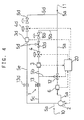
- the flow control device of this invention may include a second bypass 5d besides the bypass 5b.
- a second bypass 5d branches through a second changeover valve 12d from the bypass 5b at a point between the flow control valve 4 and the bypass back pressure regulating valve 8b.
- the second bypass 5d has a second bypass flowmeter 3d, a second bypass flow control valve 4d, and a second bypass back pressure regulating valve 8d, and merging with the main line 5a immediately before the outlet 11.
- a second return line 5e having a second needle valve 13d is provided.
- bypass lines are provided in two stages, it is possible to further reduce the flow rate with the second bypass flow control valve 4d by feeding the fluid whose flow rate has been controlled to a low level in the bypass 5b into the second bypass 5d.
- the device can control the flow rate with high accuracy over a wider flow rate range than the device in which the bypass is provided in one stage. Further, since each line 5a, 5b, 5d has a back pressure regulating valve 8a, 8b, 8d, flow control accuracy further improves for fluid flow control in any line.
- a third bypass may be provided for the second bypass.
- the flow control device of Fig. 1 was used to control the flow rate of a dye concentrate. With the inlet of the main line of the flow control device connected to the bottom of a dye concentrate tank in which was stored a dye concentrate, the flow control device was activated with the flow rate set at the values shown in Table 1. For the actual flow rate when the dye concentrate was fed for an hour, when the flow rate was high (2-20 L/min), the flow rate output from the main line flowmeter was monitored by a personal computer through an A/D converter. When the flow rate was low (0.2-2 L/min), the flow rate output from the bypass flowmeter was monitored, processed and recorded by the personal computer through an A/D converter. Based on them, the maximum flow rate fluctuation rate ((actual flow rate - predetermined flow rate) ⁇ redetermined flow rate x 100) was determined. The results are shown in Table 1.
- a gear pump (controllable flow rate : 2-20 L/min) was used as the pump of the flow control device.
- a regulating valve type HLS ACT. HAIR made by YAMATAKE Honeywell, single-acting HEP electro-pneumatic valve positioner: type HEP15-114, controllable flow rate range : 0.2-2 L/min
- a bypass back pressure regulating valve a back pressure valve (type: BV-F10SE made by Tacmina, pressure regulating range : 0.5-2.5 kgf/cm 2 ) was used.
- a back pressure valve (type: BV-F25SE made by Tacmina, pressure regulating range : 0.5-2.5 kgf/cm 2 ) was used.
- BV-F25SE made by Tacmina, pressure regulating range : 0.5-2.5 kgf/cm 2
- bypass flowmeter an electromagnetic flowmeter (detectable flow rate range : 0.2-2 L/min) was used.
- main line flowmeter an electromagnetic flowmeter (detectable flow rate range : 2-20 L/min) was used.
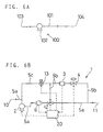
- a flow control device 100 shown in Fig. 6A and comprising a single pipe line 101 and a pump 102 provided in the line 101 was used to control the flow rate of a dye concentrate.
- the flow control device was activated with the flow rate set at the values shown in Table 2.
- the actual flow rate when the dye concentrate was fed for an hour was monitored, processed and recorded by a personal computer using a flowmeter provided at the outlet 104 of the pipe in the same manner as in Example 1. Based on them, the maximum value of the actual flow rate fluctuation rate was determined. The results are shown in Table 2.
- the pump was the same gear pump as used in Example 1. ⁇ Comparative Example 2 ⁇
- Example 3 a flow control device (shown in Fig. 6B) having neither of the bypass back pressure regulating valve 8d and the main line back pressure regulating valve 8a was used to determine the maximum value of the actual flow rate fluctuation rate in the same manner as in Example 1. The results are shown in Table 3.
- the maximum fluctuation rate was approximately within ⁇ 0.38% over a wide flow rate range of 0.2-20 L/min. It is thus possible to feed a dye concentrate while controlling the flow rate with extremely high accuracy over a wide flow rate range. In the flow rate range of 0.5-20 L/min, particularly high-accuracy flow rate control was possible. That is, the maximum fluctuation rate was within 0.19%.
- the present invention it is possible to feed fluid at a high flow rate while controlling the flow rate with high accuracy by using only the main pipe line as a flow path and adjusting only the degree of opening of the pump. It is also possible to feed fluid at a low flow rate far lower than the lower limit of the discharge flow rate range of the pump by throttling the fluid fed at a low flow rate by the pump by adjusting the degree of opening of the flow control valve. Also, since pressure fluctuation on the discharge side of the flow control valve can be suppressed by the back pressure regulating valve, it is possible to further improve the accuracy of flow rate control. Thus, it is possible to variably control the flow rate with high accuracy over a wide flow rate rage from a high to a low flow rate with a single pump, without the need to use a plurality of pumps. This reduces the cost and the installation space.
- the dye solution preparation step in the dyeing of textile products such as continuous dyeing can be carried out automatically, i.e. unmanned. Further, it is possible to improve production efficiency and the quality of production step control, and save energy. This permits a shift from a conventional labor-intensive structure to an online chemical plant type structure. This is a major technical breakthrough.
- the concept of this invention is used not only in the field of dyeing of textile products, but also in continuous mixing or continuous coloring steps in paper-making, paint, printing, food, cosmetic and chemical industries, and will make it possible to automate these steps, improve efficiency and the quality of production step control, and save energy.
Landscapes
- Physics & Mathematics (AREA)
- General Physics & Mathematics (AREA)
- Engineering & Computer Science (AREA)
- Automation & Control Theory (AREA)
- Flow Control (AREA)
Applications Claiming Priority (2)
| Application Number | Priority Date | Filing Date | Title |
|---|---|---|---|
| JP15478798A JP3430013B2 (ja) | 1998-06-03 | 1998-06-03 | 流量制御装置 |
| JP15478798 | 1998-06-03 |
Publications (2)
| Publication Number | Publication Date |
|---|---|
| EP0962846A1 true EP0962846A1 (de) | 1999-12-08 |
| EP0962846B1 EP0962846B1 (de) | 2002-03-27 |
Family
ID=15591899
Family Applications (1)
| Application Number | Title | Priority Date | Filing Date |
|---|---|---|---|
| EP98123912A Expired - Lifetime EP0962846B1 (de) | 1998-06-03 | 1998-12-16 | Vorrichtung zur Steuerung eines Durchflusses |
Country Status (5)
| Country | Link |
|---|---|
| US (1) | US6073653A (de) |
| EP (1) | EP0962846B1 (de) |
| JP (1) | JP3430013B2 (de) |
| AT (1) | ATE215242T1 (de) |
| DE (1) | DE69804432T2 (de) |
Cited By (2)
| Publication number | Priority date | Publication date | Assignee | Title |
|---|---|---|---|---|
| WO2002010874A3 (en) * | 2000-08-02 | 2002-07-18 | Honeywell Int Inc | Optical detection system for flow cytometry |
| CN111076091A (zh) * | 2020-01-06 | 2020-04-28 | 广州环投环境服务有限公司 | 一种高扬程恒流投加装置 |
Families Citing this family (18)
| Publication number | Priority date | Publication date | Assignee | Title |
|---|---|---|---|---|
| US6708104B2 (en) | 2001-07-27 | 2004-03-16 | Detroit Diesel Corporation | Engine control based on exhaust back pressure |
| DE10255514A1 (de) * | 2002-11-27 | 2004-06-09 | Endress + Hauser Gmbh + Co. Kg | Druckregelverfahren zur Vermeidung von Kavitationen in einer verfahrenstechnischen Anlage |
| FI114558B (fi) * | 2003-03-06 | 2004-11-15 | Metso Paper Inc | Menetelmä käsittelyaineen syöttämiseksi applikointilaitteelle |
| US20040261855A1 (en) * | 2003-06-27 | 2004-12-30 | Hart Justin Wade | Pressure regulator with integrated reverse pressure exhaust |
| DE10343023A1 (de) * | 2003-09-16 | 2005-04-07 | Voith Paper Patent Gmbh | Mischsystem für Farbkomponenten und Verfahren zur Herstellung von gestrichenem Papier oder Karton |
| US9189603B2 (en) | 2006-05-24 | 2015-11-17 | Confident Technologies, Inc. | Kill switch security method and system |
| JP5341427B2 (ja) * | 2008-08-20 | 2013-11-13 | 東京エレクトロン株式会社 | 基板処理装置、基板処理方法、基板処理プログラム、及び基板処理プログラムを記録したコンピュータ読み取り可能な記録媒体 |
| US8393875B2 (en) * | 2009-08-20 | 2013-03-12 | R. E. Prescott Co., Inc. | Pressure-controlled liquid supply system and pump control device for use therein |
| US9279419B2 (en) | 2013-01-16 | 2016-03-08 | Prochem Ulc | System and process for supplying a chemical agent to a process fluid |
| CN103290884B (zh) * | 2013-06-27 | 2014-11-05 | 长沙山水节能研究院有限公司 | 一种供水系统多末端支管同步调节流量的方法 |
| JP6290762B2 (ja) * | 2013-10-30 | 2018-03-07 | 東京エレクトロン株式会社 | 流量調整機構、希釈薬液供給機構、液処理装置及びその運用方法 |
| US11415123B2 (en) * | 2016-10-19 | 2022-08-16 | Halliburton Energy Services. Inc. | Controlled stop for a pump |
| KR102654820B1 (ko) * | 2017-02-07 | 2024-04-04 | 한화오션 주식회사 | 청수 냉각 시스템 및 이를 가지는 선박 |
| JP7058538B2 (ja) * | 2018-04-05 | 2022-04-22 | 東京エレクトロン株式会社 | 流量制御方法、温度制御方法及び処理装置 |
| CN110410674B (zh) * | 2019-07-31 | 2020-10-02 | 洛阳绿潮环保科技有限公司 | 一种常规计量泵实现小流量高精度计量加注的方法 |
| CN110455524B (zh) * | 2019-08-07 | 2021-03-26 | 中国北方发动机研究所(天津) | 一种单体泵控制阀流量测试装置 |
| CN115680590B (zh) * | 2021-07-21 | 2024-11-19 | 中国石油天然气集团有限公司 | 全自动配置与供应钻磨液装置和系统以及钻磨液供应方法 |
| CN114682084A (zh) * | 2022-03-28 | 2022-07-01 | 西安热工研究院有限公司 | 一种并联式脱硝还原剂流量调节系统及方法 |
Citations (4)
| Publication number | Priority date | Publication date | Assignee | Title |
|---|---|---|---|---|
| US4508127A (en) * | 1983-03-30 | 1985-04-02 | The Garrett Corporation | Fuel mass flow measurement and control system |
| US4735225A (en) * | 1985-08-19 | 1988-04-05 | Robinetterie S.F.R. S.A. | Method and apparatus for drawing and regulating the output and pressure of a liquid additive |
| US4953618A (en) * | 1989-01-12 | 1990-09-04 | Haliburton Company | Injection manifold and method |
| EP0554725A2 (de) * | 1992-02-06 | 1993-08-11 | The Lubrizol Corporation | Zusatzeinspritzsystem und -verfahren |
Family Cites Families (6)
| Publication number | Priority date | Publication date | Assignee | Title |
|---|---|---|---|---|
| US3292500A (en) * | 1965-09-17 | 1966-12-20 | Coast Elevator Company | Hydraulic elevator |
| US3543784A (en) * | 1967-10-13 | 1970-12-01 | Phillips Petroleum Co | Flow control system |
| US3633597A (en) * | 1970-05-28 | 1972-01-11 | Atomic Energy Commission | Flow rate control method |
| US4718443A (en) * | 1987-02-06 | 1988-01-12 | Conoco Inc. | Mass flowmeter apparatus |
| USH1326H (en) * | 1990-12-24 | 1994-07-05 | The United States Of America As Represented By The Secretary Of The Navy | Transient flow loop system |
| US5190068A (en) * | 1992-07-02 | 1993-03-02 | Brian Philbin | Control apparatus and method for controlling fluid flows and pressures |
-
1998
- 1998-06-03 JP JP15478798A patent/JP3430013B2/ja not_active Expired - Fee Related
- 1998-12-11 US US09/208,986 patent/US6073653A/en not_active Expired - Fee Related
- 1998-12-16 AT AT98123912T patent/ATE215242T1/de not_active IP Right Cessation
- 1998-12-16 DE DE69804432T patent/DE69804432T2/de not_active Expired - Lifetime
- 1998-12-16 EP EP98123912A patent/EP0962846B1/de not_active Expired - Lifetime
Patent Citations (4)
| Publication number | Priority date | Publication date | Assignee | Title |
|---|---|---|---|---|
| US4508127A (en) * | 1983-03-30 | 1985-04-02 | The Garrett Corporation | Fuel mass flow measurement and control system |
| US4735225A (en) * | 1985-08-19 | 1988-04-05 | Robinetterie S.F.R. S.A. | Method and apparatus for drawing and regulating the output and pressure of a liquid additive |
| US4953618A (en) * | 1989-01-12 | 1990-09-04 | Haliburton Company | Injection manifold and method |
| EP0554725A2 (de) * | 1992-02-06 | 1993-08-11 | The Lubrizol Corporation | Zusatzeinspritzsystem und -verfahren |
Cited By (2)
| Publication number | Priority date | Publication date | Assignee | Title |
|---|---|---|---|---|
| WO2002010874A3 (en) * | 2000-08-02 | 2002-07-18 | Honeywell Int Inc | Optical detection system for flow cytometry |
| CN111076091A (zh) * | 2020-01-06 | 2020-04-28 | 广州环投环境服务有限公司 | 一种高扬程恒流投加装置 |
Also Published As
| Publication number | Publication date |
|---|---|
| JP3430013B2 (ja) | 2003-07-28 |
| ATE215242T1 (de) | 2002-04-15 |
| EP0962846B1 (de) | 2002-03-27 |
| US6073653A (en) | 2000-06-13 |
| JPH11345026A (ja) | 1999-12-14 |
| DE69804432D1 (de) | 2002-05-02 |
| DE69804432T2 (de) | 2002-07-18 |
Similar Documents
| Publication | Publication Date | Title |
|---|---|---|
| US6073653A (en) | Control device | |
| US7069944B2 (en) | Flow rate control device | |
| CA1087491A (en) | Bypass valve for pumps, heating systems and the like | |
| US11839860B2 (en) | On-demand in-line-blending and supply of chemicals | |
| US6250894B1 (en) | Load sharing valve and system for operating centrifugal pumps in parallel | |
| US4632147A (en) | Dye color control system | |
| US4642984A (en) | Control device for at least one hydraulically operated load | |
| KR20000070768A (ko) | 우선 유압 소비자 및 2차 유압 소비자용 유압 제어 회로 | |
| AU2013341306B2 (en) | Fluid injection system | |
| JP3553320B2 (ja) | 流量制御装置 | |
| NL193280C (nl) | Inrichting voor het bereiden van met CO2 geïmpregneerd water, bestemd voor het begieten van planten. | |
| EP1289668B1 (de) | Sprühvorrichtung | |
| JPH0947121A (ja) | 薬液混入装置 | |
| KR850006049A (ko) | 후압력 보상 유압밸브 | |
| US4710993A (en) | Dye color control system | |
| JP2652693B2 (ja) | 流量調節弁の制御方法 | |
| KR100647503B1 (ko) | 디젤기관의 에멀션연료 공급장치 | |
| CN209014102U (zh) | 一种大范围、多方式调节文丘里管进出口压力的空化实验台 | |
| JPH02160073A (ja) | 液体のミタリング吐出方法とその装置 | |
| CN117958604B (zh) | 调压冲泡管路、咖啡机及咖啡冲泡调压控制方法 | |
| JP2556231Y2 (ja) | 薬液の流量拡大装置 | |
| JP3915775B2 (ja) | 給湯温度制御装置 | |
| JP2540629B2 (ja) | 給湯システム | |
| JPH02238225A (ja) | ボイラに於ける給湯給水安定供給装置 | |
| SU1560285A1 (ru) | Смесительна установка |
Legal Events
| Date | Code | Title | Description |
|---|---|---|---|
| PUAI | Public reference made under article 153(3) epc to a published international application that has entered the european phase |
Free format text: ORIGINAL CODE: 0009012 |
|
| AK | Designated contracting states |
Kind code of ref document: A1 Designated state(s): AT BE DE FR GB IT |
|
| AX | Request for extension of the european patent |
Free format text: AL;LT;LV;MK;RO;SI |
|
| 17P | Request for examination filed |
Effective date: 20000417 |
|
| AKX | Designation fees paid |
Free format text: AT BE DE FR GB IT |
|
| 17Q | First examination report despatched |
Effective date: 20000717 |
|
| GRAG | Despatch of communication of intention to grant |
Free format text: ORIGINAL CODE: EPIDOS AGRA |
|
| GRAG | Despatch of communication of intention to grant |
Free format text: ORIGINAL CODE: EPIDOS AGRA |
|
| GRAH | Despatch of communication of intention to grant a patent |
Free format text: ORIGINAL CODE: EPIDOS IGRA |
|
| RIN1 | Information on inventor provided before grant (corrected) |
Inventor name: KAWAKAMI, MASAO Inventor name: KIMURA, HIROSHI Inventor name: NISHIO, SHIGENORI |
|
| GRAH | Despatch of communication of intention to grant a patent |
Free format text: ORIGINAL CODE: EPIDOS IGRA |
|
| REG | Reference to a national code |
Ref country code: GB Ref legal event code: IF02 |
|
| GRAA | (expected) grant |
Free format text: ORIGINAL CODE: 0009210 |
|
| AK | Designated contracting states |
Kind code of ref document: B1 Designated state(s): AT BE DE FR GB IT |
|
| REF | Corresponds to: |
Ref document number: 215242 Country of ref document: AT Date of ref document: 20020415 Kind code of ref document: T |
|
| REF | Corresponds to: |
Ref document number: 69804432 Country of ref document: DE Date of ref document: 20020502 |
|
| ET | Fr: translation filed | ||
| PLBE | No opposition filed within time limit |
Free format text: ORIGINAL CODE: 0009261 |
|
| STAA | Information on the status of an ep patent application or granted ep patent |
Free format text: STATUS: NO OPPOSITION FILED WITHIN TIME LIMIT |
|
| 26N | No opposition filed |
Effective date: 20021230 |
|
| PGFP | Annual fee paid to national office [announced via postgrant information from national office to epo] |
Ref country code: AT Payment date: 20071219 Year of fee payment: 10 Ref country code: IT Payment date: 20071220 Year of fee payment: 10 |
|
| PGFP | Annual fee paid to national office [announced via postgrant information from national office to epo] |
Ref country code: BE Payment date: 20071221 Year of fee payment: 10 |
|
| PGFP | Annual fee paid to national office [announced via postgrant information from national office to epo] |
Ref country code: GB Payment date: 20071219 Year of fee payment: 10 |
|
| PGFP | Annual fee paid to national office [announced via postgrant information from national office to epo] |
Ref country code: FR Payment date: 20071214 Year of fee payment: 10 |
|
| BERE | Be: lapsed |
Owner name: *SUMINOE TEXTILE CO. LTD Effective date: 20081231 |
|
| GBPC | Gb: european patent ceased through non-payment of renewal fee |
Effective date: 20081216 |
|
| PG25 | Lapsed in a contracting state [announced via postgrant information from national office to epo] |
Ref country code: AT Free format text: LAPSE BECAUSE OF NON-PAYMENT OF DUE FEES Effective date: 20081216 |
|
| PG25 | Lapsed in a contracting state [announced via postgrant information from national office to epo] |
Ref country code: BE Free format text: LAPSE BECAUSE OF NON-PAYMENT OF DUE FEES Effective date: 20081231 |
|
| REG | Reference to a national code |
Ref country code: FR Ref legal event code: ST Effective date: 20090831 |
|
| PG25 | Lapsed in a contracting state [announced via postgrant information from national office to epo] |
Ref country code: GB Free format text: LAPSE BECAUSE OF NON-PAYMENT OF DUE FEES Effective date: 20081216 |
|
| PG25 | Lapsed in a contracting state [announced via postgrant information from national office to epo] |
Ref country code: FR Free format text: LAPSE BECAUSE OF NON-PAYMENT OF DUE FEES Effective date: 20081231 |
|
| PGFP | Annual fee paid to national office [announced via postgrant information from national office to epo] |
Ref country code: DE Payment date: 20100129 Year of fee payment: 12 |
|
| REG | Reference to a national code |
Ref country code: DE Ref legal event code: R119 Ref document number: 69804432 Country of ref document: DE Effective date: 20110701 |
|
| PG25 | Lapsed in a contracting state [announced via postgrant information from national office to epo] |
Ref country code: DE Free format text: LAPSE BECAUSE OF NON-PAYMENT OF DUE FEES Effective date: 20110701 |
|
| PG25 | Lapsed in a contracting state [announced via postgrant information from national office to epo] |
Ref country code: IT Free format text: LAPSE BECAUSE OF NON-PAYMENT OF DUE FEES Effective date: 20081216 |