EP0962355A2 - Vorrichtung zum Befestigen von Sitzen in Fahrzeugen - Google Patents
Vorrichtung zum Befestigen von Sitzen in Fahrzeugen Download PDFInfo
- Publication number
- EP0962355A2 EP0962355A2 EP99201676A EP99201676A EP0962355A2 EP 0962355 A2 EP0962355 A2 EP 0962355A2 EP 99201676 A EP99201676 A EP 99201676A EP 99201676 A EP99201676 A EP 99201676A EP 0962355 A2 EP0962355 A2 EP 0962355A2
- Authority
- EP
- European Patent Office
- Prior art keywords
- profile
- seat
- anchoring
- fastened
- seats
- Prior art date
- Legal status (The legal status is an assumption and is not a legal conclusion. Google has not performed a legal analysis and makes no representation as to the accuracy of the status listed.)
- Withdrawn
Links
- 238000004873 anchoring Methods 0.000 claims abstract description 53
- 230000000295 complement effect Effects 0.000 claims abstract description 6
- 230000002787 reinforcement Effects 0.000 claims abstract description 4
- 230000001154 acute effect Effects 0.000 claims abstract description 3
- 230000006978 adaptation Effects 0.000 claims 1
- 230000000284 resting effect Effects 0.000 claims 1
- 230000000717 retained effect Effects 0.000 claims 1
- 238000004519 manufacturing process Methods 0.000 description 4
- 230000003100 immobilizing effect Effects 0.000 description 3
- QNRATNLHPGXHMA-XZHTYLCXSA-N (r)-(6-ethoxyquinolin-4-yl)-[(2s,4s,5r)-5-ethyl-1-azabicyclo[2.2.2]octan-2-yl]methanol;hydrochloride Chemical compound Cl.C([C@H]([C@H](C1)CC)C2)CN1[C@@H]2[C@H](O)C1=CC=NC2=CC=C(OCC)C=C21 QNRATNLHPGXHMA-XZHTYLCXSA-N 0.000 description 2
- 230000008878 coupling Effects 0.000 description 2
- 238000010168 coupling process Methods 0.000 description 2
- 238000005859 coupling reaction Methods 0.000 description 2
- 238000004826 seaming Methods 0.000 description 2
- 238000005520 cutting process Methods 0.000 description 1
- 238000006073 displacement reaction Methods 0.000 description 1
- 230000000694 effects Effects 0.000 description 1
- 230000003028 elevating effect Effects 0.000 description 1
- 238000003780 insertion Methods 0.000 description 1
- 230000037431 insertion Effects 0.000 description 1
- 230000014759 maintenance of location Effects 0.000 description 1
- 238000003825 pressing Methods 0.000 description 1
Images


Classifications
-
- B—PERFORMING OPERATIONS; TRANSPORTING
- B60—VEHICLES IN GENERAL
- B60N—SEATS SPECIALLY ADAPTED FOR VEHICLES; VEHICLE PASSENGER ACCOMMODATION NOT OTHERWISE PROVIDED FOR
- B60N2/00—Seats specially adapted for vehicles; Arrangement or mounting of seats in vehicles
- B60N2/005—Arrangement or mounting of seats in vehicles, e.g. dismountable auxiliary seats
- B60N2/015—Attaching seats directly to vehicle chassis
-
- B—PERFORMING OPERATIONS; TRANSPORTING
- B60—VEHICLES IN GENERAL
- B60N—SEATS SPECIALLY ADAPTED FOR VEHICLES; VEHICLE PASSENGER ACCOMMODATION NOT OTHERWISE PROVIDED FOR
- B60N2/00—Seats specially adapted for vehicles; Arrangement or mounting of seats in vehicles
- B60N2/24—Seats specially adapted for vehicles; Arrangement or mounting of seats in vehicles for particular purposes or particular vehicles
- B60N2/242—Bus seats
Definitions
- the present invention refers to an improved device to fasten seats to vehicles, comprising two independent anchorings for each pair of seats that are situated on both sides of the center aisle of the vehicle.
- One of the anchorings of the device is provided for to fasten and immobilize the seat that is located at the aisle side, while the other anchoring constitutes the means to fasten and immobilize the seat of the window side of the vehicle.
- the object of the invention is not only to achieve effective fastening and immobilizing of the pair of seats, but also to allow the user to carry out the fastening or anchoring operation in a simple and rapid manner, with a noteworthy time saving with respect to the time required by other devices provided for with the same purpose.
- the corresponding seats tend to be mounted in pairs, in such a way that each pair is located between the aisle and the side of the vehicle.
- the seat that is located on the aisle side are based on a specially shaped profile integral to the support leg or column of the seat, profile that is anchored by means of a type of seaming in another one fastened for this purpose in the floor of the vehicle, all in such a way that the anchoring or seaming of a profile in another one is done by means of tilting of the assembly of the two seats, elevating the part of the side corresponding to the seat located in the side, without the locking means of the aisle side interfere, to then make a small displacement towards the side itself together with a tilting downward, in order to achieve the anchoring and retention to each other of the two profiles that form part of the fastening of the seat located in the aisle side, and whose two profiles are: the one integral to the part of the seat and the one located on the floor.
- the shape of the profile fastened to the floor is such that a rectangular recess with the top edge projecting and rounded and the bottom part of the recess with an arched supra-elevation determining a concave bottom on which the bottom edge of the profile integral to the foot or leg of the seat is positioned, are formed in the same.
- Said profile begins as of a straight branch through which the leg of the seat becomes integral, whose branch at its front edge continues in a special shape defining the profile itself, which has a rounded top section with a convexity outward, followed by a vertical section that ends in an elbow rounded upward and inward, forming an end with a practically semi-circular section for seating in the concave bottom of the profile fastened to the floor, while the top projecting and rounded edge thereof is located in the complementary shape that defines the top rounded section of the profile integral to the foot or leg of the seat.
- the anchoring of the window side seat is carried out by means of a square-shaped part or plate with a wing that is abutted and fastened to the inside surface of the profile fastened to the side of the vehicle, while the other wing is larger and constitutes the fastening means for the bottom part corresponding to the seat.
- the fastening of the square-shaped plate to the profile located in the side of the vehicle is carried out by a threaded rod ending in a generally rhombic-shaped head that, in a specific position, is made to pass through a longitudinal channel provided for in the respective inside surface of the profile fastened to side of the vehicle, in such a way that the rhombic head is kept in its position by means of the transversal rod threaded in a hole of the head, the head abutting on the outside surface of the wing or branch corresponding to the plate constituting the anchoring, all in such a way that the tightening of the rod implies the fastening and immobilizing of the anchoring and therefore of the seat.
- the anchoring is complemented with a safety part that blocks and prevents the rotation of the rhombic shaped head housed in the stationary side profile of the vehicle, said safety part being provided with a hole for the passage of the corresponding fastening rod and of a side and transversal wing that is blocked between the groove that defines two side expansions belonging to an axial groove provided for in correspondence with each one of the ends of the wing corresponding to the square-shaped profile, all in such a way that in the assembly of that safety part, the side wing thereof is close and parallel to one of the longitudinal edges of the rhombic-shaped head, preventing the rotation thereof preventing it from coming out of the channel, in those cases in which for any reason the corresponding fastening rod becomes loose.
- the fastening device for vehicle seats object of the invention based on the two above mentioned types of anchorings, in other words in those described in Spanish utility model application U-9600173, has a series of innovations and improvements of those from which advantages are derived with respect to the previously mentioned anchoring system, from the functional point of view as well as from the point of view of manufacturing or obtainment of the different parts or profiles that intervene in the anchorings.
- the improvements have been conceived to solve manufacturing problems of the profile and to achieve a saving of material, even a more effective anchoring.
- a basic improvement consists of the bottom edge of the profile integral with the leg or foot of the seat, being straight and the end section corresponding to the same being inclined forward, forming an acute angle with the front section from which it is derived.
- Another improvement consists of the horizontal section from which the inclined and bottom section referred to in the above point is derived, being larger in order to define a deeper cavity, in which the top rounded edge of the profile fastened to the floor will be more enveloped in the corresponding anchoring, in such a way that this top encircling, along with the slant and straightness of the bottom end section of the profile fastened to the part of the seat, provide a more secure and more effective anchoring.
- the profile of the described anchor is conceived in order to be mounted on the side of the step that is defined between the aisle and the area of the seats, the latter being higher, it has been provided for that in the event that the floor does not have a step the profile will then have a special shape, specifically in the form of a horizontal channel with the top strangled opening and side wings horizontal thereto, being complemented with a closing cover of the channel, that is interrupted in the areas where the anchoring of the seat takes place.
- the square-shaped profile instead of being a single and considerably long part, is defined by two small parts with an identical shape and both fastenable in an independent manner in the bottom part of the seat, each one of them anchoring to the corresponding profile fastened in the side of the vehicle, intervening the threaded rod with its rhombic-shaped head, the safety part that constitutes the nonrotating means of the previous one, etc.
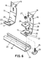
- the device of the invention is provided for to fasten a pair of seats (1) and (2), the first one located on the center aisle side of a bus or similar vehicle, and the second seat is located on the side, that is to say, on the window side.
- the two seats (1) and (2) for a single assembly that is fastened by means of two independent anchorings, one located on the aisle side, logically for the anchoring of the seat (1) and the other one located on the side, logically for the fastening of the seat (2).
- the anchoring by means of which the fastening of the seat (1) will be carried out is constituted as of a section (3) that is integral to the bottom part of the corresponding leg (4) of the seat (1), carrying out this locking or fastening by means of the branch corresponding to reference (3) itself of the profile.
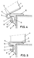
- That horizontal branch of the profile (3) has frontally a rounded elbow (5) that defines a groove (6) whose function will be explained later on, which as of whose rounding (5) it continues, after another elbow (7), in a straight and inclined bottom section (8), with an angulation slightly less than 90o.
- That section (3) is provided for its coupling on a section profile (9) fastened to the floor of the vehicle, said profile (9) having a top and horizontal section (10) that is longitudinally ribbed and that frontally forms a groove (11) with a concave bottom (12), as of which a short arched wing slightly slanted outward, referred to as (13), projects.
- the assembly and corresponding anchoring of that part of the seat (1) is done as of the position represented in figure 3, wherein the profiles (3) and (9) are totally separated, in such a way that as of that position it will be necessary to first of all move the assembly of the seats (1) and (2) towards the side of the aisle, and in turn tilt it upward from the opposite side part, in other words from the seat (2), in order to then pull it towards that side for the purpose of achieving that the straight and oblique section (8) of the profile (3) is located in the housing (11) of the profile (9) fastened to the floor, in order to then carry out the tilting towards the horizontal position, the section (14) of the profile (9) being in the groove (6) of the profile (3), and in turn the bottom straight and oblique section (8) of the profile (3) anchored in the concave bottom (12), levering said profile (9), as it is clearly shown in figure 5.
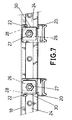
- the same is carried out as of a pair of square-shaped parts (15), in such a way that through its longer branch (16), they are fastened to the bottom part of the seat (2), as is shown in figure 1, while through its shorter branch (17), the fastening to the guiding profile (18) fastened horizontally to the side of the vehicle is carried out, as represented in figure 1.
- the longer branch (16) has an obtuse angle, as well as an elongated hole for the anchoring to the bottom part of the seat itself (2), at the same time that the side edges of said branch (16), in correspondence with the end thereof, have some small oblique lugs (19), by cutting the same material, that are adopted collaterally to the corresponding profile or bottom part of the seat (2) in which the fastening is carried out, while in the angulation between the branches (16) and (17) of the square-shaped parts or profiles (15), there is a heel or oblique and outside wing (20) that presses against the outside surface corresponding to the side and top branch of the profile (18) to which the square-shaped parts (15) are fastened.
- each one of these parts (21) has a groove (21), with a side notch (22) (a side expansion of the groove (21)) close to its mouth, all of this in such a way that the branch (17) is abutted in correspondence with the outside surface of the profile (18), specifically on the surface on which the longitudinal throat (23) of said profile (18) is made, given that the profile defines a U-shaped groove (24), with the strangulated mouth defining that throat (23) which was alluded to.
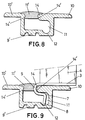
- the anchoring is done by means of the intervention of a rod (25) with a rhombic-shaped head (26), that may slide over the channel (24) of the profile (18) in order to carry out the assembly, the rod (25) being located in correspondence with the throat (23) of the profile (18) and in turn housed in the groove (21), carrying out the fastening by the corresponding nut (27) that screws on the above mentioned rod (25), thus pressing and fastening the square-shaped part (15), by means of its branch (17), against the profile (18).
- a complementary safety part (28) that has a quadrangular shape with a part that is housed in the inside of the channel (24) of the profile (18), part (28) that has a hole (29) for the passage of the rod itself (25), at the same time that said part (28) has a perpendicular branch (30) that is housed precisely in the throat that defines the side notch (22) of the groove (21), thus immobilizing part (28), all of this which when one of the surfaces of the head (26) of the rod (25) abuts against the branch (30), said rod will not be able to turn, since the part (28) is anchored by means of its branch (30), as it has just been put forth.
- Said profile (9') is complemented with a cover (11') arranged longitudinally to close the mouth of the U-shaped channel that forms said profile (9'), in such a way that the cover (11') will be constituted by a profile of rubber or the like that will be interrupted in those sections in which the part of the profile (3) corresponding to the part to which the leg or column (4) of the seat is integral has to be hooked.
- the fastening or retaining of the cover (11') is carried out by insertion of side projections thereof in steps (14') provided for in the opposite parts that define the mouth or opening of the cited grooved profile.
Landscapes
- Engineering & Computer Science (AREA)
- Aviation & Aerospace Engineering (AREA)
- Transportation (AREA)
- Mechanical Engineering (AREA)
- Seats For Vehicles (AREA)
Applications Claiming Priority (3)
| Application Number | Priority Date | Filing Date | Title |
|---|---|---|---|
| ES9801425U | 1998-06-02 | ||
| ES9801425 | 1998-06-02 | ||
| ES9801425U ES1040518Y (es) | 1998-06-02 | 1998-06-02 | Dispositivo perfeccionado de fijacion de butacas a vehiculos. |
Publications (2)
| Publication Number | Publication Date |
|---|---|
| EP0962355A2 true EP0962355A2 (de) | 1999-12-08 |
| EP0962355A3 EP0962355A3 (de) | 2001-10-04 |
Family
ID=8304414
Family Applications (1)
| Application Number | Title | Priority Date | Filing Date |
|---|---|---|---|
| EP99201676A Withdrawn EP0962355A3 (de) | 1998-06-02 | 1999-05-27 | Vorrichtung zum Befestigen von Sitzen in Fahrzeugen |
Country Status (2)
| Country | Link |
|---|---|
| EP (1) | EP0962355A3 (de) |
| ES (1) | ES1040518Y (de) |
Cited By (4)
| Publication number | Priority date | Publication date | Assignee | Title |
|---|---|---|---|---|
| WO2007022853A1 (de) * | 2005-08-26 | 2007-03-01 | Daimlerchrysler Ag | Befestigungsvorrichtung |
| DE102008039165A1 (de) * | 2008-08-21 | 2010-02-25 | Siemens Aktiengesellschaft | Befestigungsanordnung für ein wand- und bodengestütztes Element einer Innenausstattung eines Fahrzeuges |
| FR2935682A1 (fr) * | 2008-09-05 | 2010-03-12 | Airbus France | Struture d'ensemble de siege pour aeronef et fuselage adapte |
| US8845225B2 (en) | 2011-02-24 | 2014-09-30 | Siemens Aktiengesellschaft | Fastening arrangement for a wall-supported and floor-supported element of an interior fitting of a vehicle |
Families Citing this family (1)
| Publication number | Priority date | Publication date | Assignee | Title |
|---|---|---|---|---|
| CN111976844B (zh) * | 2020-08-20 | 2022-07-01 | 东风柳州汽车有限公司 | 车身地板总成、中排座椅安装结构及车辆 |
Family Cites Families (5)
| Publication number | Priority date | Publication date | Assignee | Title |
|---|---|---|---|---|
| FR2135828A5 (de) * | 1971-04-30 | 1972-12-22 | Saviem | |
| DE2715548C3 (de) * | 1977-04-07 | 1980-10-16 | Ramseier & Jenzer Ag Carosseriewerke Bern, Bern | Seitenwand für Omnibusse |
| FR2494789A1 (fr) * | 1980-11-26 | 1982-05-28 | Renault Vehicules Ind | Dispositif de fixation, notamment pour sieges de vehicules |
| GB9011856D0 (en) * | 1990-05-26 | 1990-07-18 | Dunlop Cox Ltd | Vehicle seat attachment |
| FR2706409B1 (fr) * | 1993-06-17 | 1995-10-06 | Peugeot | Dispositif d'accrochage réversible d'un siège sur un plancher de véhicule automobile. |
-
1998
- 1998-06-02 ES ES9801425U patent/ES1040518Y/es not_active Expired - Fee Related
-
1999
- 1999-05-27 EP EP99201676A patent/EP0962355A3/de not_active Withdrawn
Cited By (8)
| Publication number | Priority date | Publication date | Assignee | Title |
|---|---|---|---|---|
| WO2007022853A1 (de) * | 2005-08-26 | 2007-03-01 | Daimlerchrysler Ag | Befestigungsvorrichtung |
| DE102008039165A1 (de) * | 2008-08-21 | 2010-02-25 | Siemens Aktiengesellschaft | Befestigungsanordnung für ein wand- und bodengestütztes Element einer Innenausstattung eines Fahrzeuges |
| DE102008039165B4 (de) * | 2008-08-21 | 2018-02-08 | Siemens Aktiengesellschaft | Befestigungsanordnung für ein wand- und bodengestütztes Element einer Innenausstattung eines Fahrzeuges |
| FR2935682A1 (fr) * | 2008-09-05 | 2010-03-12 | Airbus France | Struture d'ensemble de siege pour aeronef et fuselage adapte |
| WO2010026345A3 (fr) * | 2008-09-05 | 2010-05-20 | AIRBUS OPERATIONS (Société par actions simplifiée) | Structure d'ensemble siège pour aéronef et fuselage adapté |
| US20110260003A1 (en) * | 2008-09-05 | 2011-10-27 | AIRBUS OPERATIONS (inc as a Societe par Act Simpl) | Aircraft seat assembly structure, and fitted fuselage |
| US8714484B2 (en) | 2008-09-05 | 2014-05-06 | Airbus Operations S.A.S. | Aircraft seat assembly structure, and fitted fuselage |
| US8845225B2 (en) | 2011-02-24 | 2014-09-30 | Siemens Aktiengesellschaft | Fastening arrangement for a wall-supported and floor-supported element of an interior fitting of a vehicle |
Also Published As
| Publication number | Publication date |
|---|---|
| ES1040518Y (es) | 1999-08-16 |
| EP0962355A3 (de) | 2001-10-04 |
| ES1040518U (es) | 1999-04-16 |
Similar Documents
| Publication | Publication Date | Title |
|---|---|---|
| AU666148B2 (en) | Mounting devices | |
| JP4592759B2 (ja) | 軌道設備のためのレール締結装置 | |
| US6588711B2 (en) | Fastening fixture | |
| KR101276410B1 (ko) | 격자를 위한 홀딩 요소 | |
| US6179399B1 (en) | Fastening device for a drawer | |
| US6478501B1 (en) | Coupling member for the face end coupling of profile bars | |
| US4263952A (en) | Fastener for metal framing | |
| US9523174B2 (en) | System for fastening a rail on a subsurface | |
| KR20020047184A (ko) | 턴버클 장치 | |
| EP0962355A2 (de) | Vorrichtung zum Befestigen von Sitzen in Fahrzeugen | |
| US3293819A (en) | Wall paneling clip | |
| US20010047566A1 (en) | Fastening plate to fasten a hinge arm of a furniture hinge | |
| EP0200511B1 (de) | Befestigungszubehör zum Sichern von Ladegut auf einer Verankerungsschiene | |
| GB2419854A (en) | Vehicle seat anchoarge system | |
| GB2414029A (en) | Cladding elements | |
| US20070144954A1 (en) | Drainage device | |
| KR102478022B1 (ko) | 터널공사용 대차의 레일 슬리퍼 | |
| CA2196515C (en) | Drawer | |
| US12146271B2 (en) | Vehicle rail mounting device | |
| KR100270860B1 (ko) | 데크플레이트용 천정매달림 행거 | |
| JP3865381B2 (ja) | 手摺の角度調節構造 | |
| US4629355A (en) | Device for attaching a scaffolding bracket to a frame member, and fixing assembly for implementing same | |
| RU2848745C1 (ru) | Фиксатор решётки для водоотводного лотка | |
| KR970005489Y1 (ko) | 건축 공사용품에 있어 지주의 높낮이 조절구조 | |
| FR2589896A1 (fr) | Profile support extrude en i pour voies suspendues. |
Legal Events
| Date | Code | Title | Description |
|---|---|---|---|
| PUAI | Public reference made under article 153(3) epc to a published international application that has entered the european phase |
Free format text: ORIGINAL CODE: 0009012 |
|
| AK | Designated contracting states |
Kind code of ref document: A2 Designated state(s): AT BE CH CY DE DK ES FI FR GB GR IE IT LI LU MC NL PT SE |
|
| AX | Request for extension of the european patent |
Free format text: AL;LT;LV;MK;RO;SI |
|
| PUAL | Search report despatched |
Free format text: ORIGINAL CODE: 0009013 |
|
| AK | Designated contracting states |
Kind code of ref document: A3 Designated state(s): AT BE CH CY DE DK ES FI FR GB GR IE IT LI LU MC NL PT SE |
|
| AX | Request for extension of the european patent |
Free format text: AL;LT;LV;MK;RO;SI |
|
| RIC1 | Information provided on ipc code assigned before grant |
Free format text: 7B 60N 2/00 A, 7B 60N 2/24 B, 7B 60N 2/015 B |
|
| AKX | Designation fees paid | ||
| REG | Reference to a national code |
Ref country code: DE Ref legal event code: 8566 |
|
| STAA | Information on the status of an ep patent application or granted ep patent |
Free format text: STATUS: THE APPLICATION IS DEEMED TO BE WITHDRAWN |
|
| 18D | Application deemed to be withdrawn |
Effective date: 20020405 |