EP0961395A2 - Dispositif de contrÔle de redémarrage automatique pour une électropompe submersible - Google Patents
Dispositif de contrÔle de redémarrage automatique pour une électropompe submersible Download PDFInfo
- Publication number
- EP0961395A2 EP0961395A2 EP99303020A EP99303020A EP0961395A2 EP 0961395 A2 EP0961395 A2 EP 0961395A2 EP 99303020 A EP99303020 A EP 99303020A EP 99303020 A EP99303020 A EP 99303020A EP 0961395 A2 EP0961395 A2 EP 0961395A2
- Authority
- EP
- European Patent Office
- Prior art keywords
- motor
- speed
- restarting
- unpowered
- determined
- Prior art date
- Legal status (The legal status is an assumption and is not a legal conclusion. Google has not performed a legal analysis and makes no representation as to the accuracy of the status listed.)
- Withdrawn
Links
- 238000000034 method Methods 0.000 claims abstract description 13
- 238000000819 phase cycle Methods 0.000 claims abstract description 10
- 239000003129 oil well Substances 0.000 claims description 9
- 230000005389 magnetism Effects 0.000 claims description 4
- 239000007788 liquid Substances 0.000 claims description 3
- 238000005070 sampling Methods 0.000 claims 3
- 238000009987 spinning Methods 0.000 description 3
- 238000010586 diagram Methods 0.000 description 2
- 238000004519 manufacturing process Methods 0.000 description 2
- 238000005086 pumping Methods 0.000 description 2
- 238000004804 winding Methods 0.000 description 2
- 230000003247 decreasing effect Effects 0.000 description 1
- 230000005484 gravity Effects 0.000 description 1
- 230000000284 resting effect Effects 0.000 description 1
- 239000007787 solid Substances 0.000 description 1
Images


Classifications
-
- F—MECHANICAL ENGINEERING; LIGHTING; HEATING; WEAPONS; BLASTING
- F04—POSITIVE - DISPLACEMENT MACHINES FOR LIQUIDS; PUMPS FOR LIQUIDS OR ELASTIC FLUIDS
- F04B—POSITIVE-DISPLACEMENT MACHINES FOR LIQUIDS; PUMPS
- F04B47/00—Pumps or pumping installations specially adapted for raising fluids from great depths, e.g. well pumps
- F04B47/06—Pumps or pumping installations specially adapted for raising fluids from great depths, e.g. well pumps having motor-pump units situated at great depth
Definitions
- the invention relates to a method and apparatus for controlling the operations of a motor, and more particularly to a method and apparatus for automatically restarting a motor/pump assembly after a power interruption.
- FIG. 1 illustrates a typical oil well assembly.
- a well 10 is drilled into the earth perhaps thousands of feet down to an oil bearing strata.
- a motor 14 which drives a pump 16 are lowered to the bottom of the well.
- the motor 14 is electrically connected by a cable 22 to a drive system 20, typically located outside the well, which provides drive signals to the motor 14.
- the drive signals control the operation of the motor 14 which in turn controls the operations of the pump 16.
- the motor 14 When the motor 14 is turned on, the motor turns the pump 16 so that oil is drawn out of the bottom of the well and up the pipe 18 to the surface creating a positive flow 24.
- the downtime of the pump reduces the production capability of the well.
- One source of downtime occurs when there is a power interruption to the system caused by a power outage, blown circuit breaker, controlled stop or the like.
- the drive system loses control of the motor because control signals can no longer be sent to the motor.
- the motor and pump will continue to operate for at least a certain period of time depending on how fast the motor was turning at the time the power was interrupted. The speed of the motor will slowly decrease until the motor and pump come to a complete stop.
- a centrifuge is used to separate solids in liquid samples by spinning the sample around a circle at high speeds.
- the momentum and weight of the centrifuge will keep the samples spinning at decreasing speeds until the centrifuge comes to a complete stop due to friction and other forces.
- One known control system can restart the motor after the power is turned back on by first determining the actual speed of the unpowered motor and applying drive signals to the motor that match the actual speed of the motor. This is performed by analyzing the back EMF signals produced by the motor's residual magnetism created by the unpowered spinning motion of the motor.
- the matching drive signals are sent to the motor to regain control of the centrifuge and additional control signals can be applied to change the centrifuge's speed to a desired level.
- additional control signals can be applied to change the centrifuge's speed to a desired level.
- a method for restarting a motor of a submersible pump after a power interruption is disclosed.
- the system first detects when the power is turned back on to the system.
- a control means then samples signals sent back from the unpowered motor and determines the frequency and phase sequence of the signals.
- the speed and direction of operation ofthe motor are then determined from the determined frequency and phase sequence.
- a first pulse width modulation waveform is then applied to the motor matching the determined speed and direction of the motor.
- the output frequency of the waveform can be adjusted to adjust the speed and direction of operation of the motor until the motor reaches a desired speed and direction of operation.
- a system for automatically restarting a motor after a power interruption is disclosed.
- a pump is connected to and driven by the motor, and the motor and the pump are located in a well.
- a cable connects the motor to an adjustable speed motor drive via a transformer so that signals can pass back and forth from the motor and the adjustable speed motor drive.
- the adjustable speed motor drive comprises several elements such as means for receiving signals from said motor before power is returned to the motor; means for determining frequency and phase sequence of the signals; means for determining speed and direction of operation of the motor from the determined frequency and phase sequence; means for generating a first modulation waveform which matches the determined speed and direction of operation of the motor; and means for transmitting the first modulation waveform to the motor through the cable.
- the output frequency of the waveform can then be adjusted to adjust the speed and direction of operation of the motor until the motor reached a desired speed and direction of operation.
- FIG. 2 illustrates an oil well pumping assembly according to one embodiment of the invention.
- a well 100 is drilled into the earth perhaps thousands of feet down to an oil bearing strata.
- a motor 104 which drives a pump 106 are lowered to the bottom of the well.
- the motor 104 is electrically connected by a cable 112 to a drive system 110, typically located outside the well, which provides drive signals to the motor 104.
- the drive signals control the operation of the motor 104 which in turn controls the operations of the pump 106.
- the motor 104 When the motor 104 is turned on, the motor turns the pump 106 so that oil is drawn out of the bottom of the well and up the pipe 108 to the surface creating a positive flow 114.
- the adjustable speed drive system 110 comprises at least a transfomer 114, a power module 118 and a control processor 120.
- the primary windings of the transformer 114 are connected to the power module 118 and the power module 118 is connected to the control processor 120.
- the control processor 120 can also be implemented as a part of the power module 118.
- the secondary windings of the transformer 114 are connected to the cable 112.
- modulation waveforms such as pulse width modulation (PWM) waveforms and power are generated by the power module and the control process 120 and applied to the transformer 114.
- the transformer 114 transforms the signals to the appropriate power level and transmits the signals to the motor 104 through the cable 112.
- PWM pulse width modulation
- the drive system 110 loses power and PWM waveforms can no longer be sent to the motor.
- the drive system does not know how fast and in what direction the unpowered motor is operating.
- restarting the motor at the wrong speed or direction of operation can damage the motor or cause a circuit breaker to trip in the drive system.
- the invention determined the speed and the direction of operation of the unpowered motor before restarting the system.
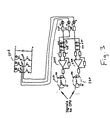
- the drive system 110 samples the frequency of the EMF signals at the drive terminals 202,204,206 of an IGBT bridge 208 of the three phase (U,V,W) power module.
- the sampled signals of the three drive terminals are fed through resistors 210,212,214 respectively, to two comparator circuits. Two phases are fed to each comparator circuit. For example, as illustrated in Figure 3, phases U and V are fed to the top comparator circuit and phases U and W are fed to the bottom comparator circuit but the invention is not limited thereto.
- the signals are passed through clamping diodes 216,218 and 220,222 respectively to prevent the comparator from being driven too hard.
- the comparator 224 If the V phase signal applied to the comparator 224 is stronger than the U phase signal, the comparator will turn on which will turn on the photocoupler 226. Likewise, if the U phase signal is stronger than the V phase signal, the comparator 224 will not turn on and the photocoupler 226 will not turn on.
- the lower comparator 228 operates in the same manner with the W and U phase signals. When the W phase signal is stronger than the U phase signal, the comparator 228 will turn on causing the photocoupler 230 to turn on.
- the signals produced by the photocouplers 226 and 230 are then applied to the control processor 120.
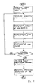
- the control processor 120 determines the frequency of the signals from the photocouplers by counting the time between the edges of the signals.
- the control processor 120 determines the period of the signals produced by the photocouplers to determine the speed of the motor.
- the control processor 120 determines which phase is the leading phase by determining the order in which the photocouplers 226 and 230 are being activated. From the determined leading edge, the control processor can determine the direction of operation of the motor.
- the control processor waits until it has received at least two and preferably three or more consistent readings before attempting to regain control of the motor. Once the control processor has received consistent readings, the control processor and power module generate a modulation waveform such as a pulse width modulation waveform approximately matching the detected speed and direction of operation of the motor. The modulation waveform is then sent to the motor, thus reestablishing control of the motor. Once control has been reestablished, the control processor and power module can modify the output frequency of the modulation waveform to return the motor to the desired speed and direction of operation.
Landscapes
- Engineering & Computer Science (AREA)
- Mechanical Engineering (AREA)
- General Engineering & Computer Science (AREA)
- Control Of Ac Motors In General (AREA)
- Control Of Non-Positive-Displacement Pumps (AREA)
- Structures Of Non-Positive Displacement Pumps (AREA)
- Control Of Positive-Displacement Pumps (AREA)
- Motor And Converter Starters (AREA)
Applications Claiming Priority (2)
| Application Number | Priority Date | Filing Date | Title |
|---|---|---|---|
| US66974 | 1979-08-16 | ||
| US09/066,974 US5973465A (en) | 1998-04-28 | 1998-04-28 | Automotive restart control for submersible pump |
Publications (2)
| Publication Number | Publication Date |
|---|---|
| EP0961395A2 true EP0961395A2 (fr) | 1999-12-01 |
| EP0961395A3 EP0961395A3 (fr) | 2002-04-24 |
Family
ID=22072928
Family Applications (1)
| Application Number | Title | Priority Date | Filing Date |
|---|---|---|---|
| EP99303020A Withdrawn EP0961395A3 (fr) | 1998-04-28 | 1999-04-19 | Dispositif de contrôle de redémarrage automatique pour une électropompe submersible |
Country Status (4)
| Country | Link |
|---|---|
| US (1) | US5973465A (fr) |
| EP (1) | EP0961395A3 (fr) |
| JP (1) | JP4260979B2 (fr) |
| CA (1) | CA2268690C (fr) |
Cited By (1)
| Publication number | Priority date | Publication date | Assignee | Title |
|---|---|---|---|---|
| RU2433519C2 (ru) * | 2007-03-09 | 2011-11-10 | Атлас Копко Энергаз Гмбх | Способ повторного подключения трехфазного двигателя и электрическая схема |
Families Citing this family (32)
| Publication number | Priority date | Publication date | Assignee | Title |
|---|---|---|---|---|
| WO2002089307A1 (fr) * | 2001-04-27 | 2002-11-07 | Special Technology Products, Inc. | Procede et appareil de commande du dispositif d'attaque d'un moteur de pompe de puits |
| US8337166B2 (en) * | 2001-11-26 | 2012-12-25 | Shurflo, Llc | Pump and pump control circuit apparatus and method |
| US20070017672A1 (en) * | 2005-07-22 | 2007-01-25 | Schlumberger Technology Corporation | Automatic Detection of Resonance Frequency of a Downhole System |
| US8540493B2 (en) | 2003-12-08 | 2013-09-24 | Sta-Rite Industries, Llc | Pump control system and method |
| US7845913B2 (en) | 2004-08-26 | 2010-12-07 | Pentair Water Pool And Spa, Inc. | Flow control |
| US8019479B2 (en) | 2004-08-26 | 2011-09-13 | Pentair Water Pool And Spa, Inc. | Control algorithm of variable speed pumping system |
| US7854597B2 (en) | 2004-08-26 | 2010-12-21 | Pentair Water Pool And Spa, Inc. | Pumping system with two way communication |
| US8469675B2 (en) | 2004-08-26 | 2013-06-25 | Pentair Water Pool And Spa, Inc. | Priming protection |
| US8480373B2 (en) | 2004-08-26 | 2013-07-09 | Pentair Water Pool And Spa, Inc. | Filter loading |
| US8602745B2 (en) * | 2004-08-26 | 2013-12-10 | Pentair Water Pool And Spa, Inc. | Anti-entrapment and anti-dead head function |
| US7686589B2 (en) | 2004-08-26 | 2010-03-30 | Pentair Water Pool And Spa, Inc. | Pumping system with power optimization |
| US7874808B2 (en) | 2004-08-26 | 2011-01-25 | Pentair Water Pool And Spa, Inc. | Variable speed pumping system and method |
| AU2007203698B2 (en) * | 2006-08-16 | 2012-11-22 | Irrisys Pty Ltd | Electric Motor Controller |
| EP2122177B1 (fr) * | 2007-02-21 | 2018-11-21 | Grundfos Management A/S | Groupe motopompe |
| US8092190B2 (en) * | 2007-04-06 | 2012-01-10 | Baker Hughes Incorporated | Systems and methods for reducing pump downtime by determining rotation speed using a variable speed drive |
| GB2450157B (en) * | 2007-06-15 | 2011-12-21 | Baker Hughes Inc | System for determining an initial direction of rotation of an electrical submersible pump |
| WO2010042406A1 (fr) | 2008-10-06 | 2010-04-15 | Pentair Water Pool And Spa, Inc. | Procédé d’actionnement d’un système brise-vide de sécurité |
| US8564233B2 (en) | 2009-06-09 | 2013-10-22 | Sta-Rite Industries, Llc | Safety system and method for pump and motor |
| US9556874B2 (en) | 2009-06-09 | 2017-01-31 | Pentair Flow Technologies, Llc | Method of controlling a pump and motor |
| US8436559B2 (en) | 2009-06-09 | 2013-05-07 | Sta-Rite Industries, Llc | System and method for motor drive control pad and drive terminals |
| US8287246B2 (en) * | 2009-08-06 | 2012-10-16 | Baker Hughes Incorporated | Systems and methods for automatic forward phasing determination in a downhole pump system |
| EP2420679A1 (fr) * | 2010-08-19 | 2012-02-22 | ABB Oy | Procédé, agencement et produit de programme informatique pour déterminer la direction de circulation correcte d'un appareil générateur de flux fluide |
| SG191067A1 (en) | 2010-12-08 | 2013-08-30 | Pentair Water Pool & Spa Inc | Discharge vacuum relief valve for safety vacuum release system |
| AU2012332382B2 (en) | 2011-11-01 | 2016-11-03 | Daniel J. Hruby | Flow locking system and method |
| US9885360B2 (en) | 2012-10-25 | 2018-02-06 | Pentair Flow Technologies, Llc | Battery backup sump pump systems and methods |
| DE102014202198B4 (de) * | 2014-02-06 | 2026-03-05 | Robert Bosch Gmbh | Verfahren zur Überprüfung eines automatischen Parkbremssystems |
| CN103916000B (zh) * | 2014-03-05 | 2017-01-04 | 深圳市海浦蒙特科技有限公司 | 变频器飞车启动控制方法 |
| US20170051590A1 (en) * | 2015-08-20 | 2017-02-23 | Baker Hughes Incorporated | Systems and Methods for Determining Forces on a Linear Permanent Magnet Motor Using Instantaneous Current Vectors |
| US9991836B2 (en) * | 2015-10-16 | 2018-06-05 | Baker Hughes Incorporated | Systems and methods for identifying end stops in a linear motor |
| EP3692377B1 (fr) * | 2017-07-23 | 2023-03-29 | Magnetic Pumping Solutions, LLC | Procédé et système de surveillance d'éléments mobiles |
| US11811273B2 (en) | 2018-06-01 | 2023-11-07 | Franklin Electric Co., Inc. | Motor protection device and method for protecting a motor |
| US10454267B1 (en) * | 2018-06-01 | 2019-10-22 | Franklin Electric Co., Inc. | Motor protection device and method for protecting a motor |
Family Cites Families (9)
| Publication number | Priority date | Publication date | Assignee | Title |
|---|---|---|---|---|
| US3875463A (en) * | 1974-03-14 | 1975-04-01 | Dunham Associates Inc | Motor protection circuit and automatic restart control system |
| US4021700A (en) * | 1975-06-04 | 1977-05-03 | Borg-Warner Corporation | Digital logic control system for three-phase submersible pump motor |
| US4103316A (en) * | 1977-05-12 | 1978-07-25 | Sanki Denshi Kogyo Kabushiki Kaisha | Apparatus for preventing the occurrence of possible transient phenomena in an electric power transmission circuit |
| JPS558250A (en) * | 1978-06-30 | 1980-01-21 | Mitsubishi Electric Corp | Method restarting induction motor |
| US4330740A (en) * | 1979-09-28 | 1982-05-18 | Centrilift-Hughes, Inc. | Energizing circuit for providing low voltage starting for submersible pump motor |
| US4438383A (en) * | 1982-07-15 | 1984-03-20 | Etheridge Electric, Inc. | Rock crusher motor control circuit for preventing relay drop out |
| US5198734A (en) * | 1992-03-09 | 1993-03-30 | Marathon Oil Company | Method and means for stopping backspinning motor |
| JP3156346B2 (ja) * | 1992-03-19 | 2001-04-16 | 株式会社日立製作所 | インバータ装置及びその瞬時停電再始動方法 |
| JPH0654586A (ja) * | 1992-07-28 | 1994-02-25 | Fuji Electric Co Ltd | 同期電動機駆動用インバータの瞬停再起動装置 |
-
1998
- 1998-04-28 US US09/066,974 patent/US5973465A/en not_active Expired - Lifetime
-
1999
- 1999-04-14 CA CA002268690A patent/CA2268690C/fr not_active Expired - Lifetime
- 1999-04-19 EP EP99303020A patent/EP0961395A3/fr not_active Withdrawn
- 1999-04-28 JP JP12189199A patent/JP4260979B2/ja not_active Expired - Lifetime
Non-Patent Citations (1)
| Title |
|---|
| None |
Cited By (1)
| Publication number | Priority date | Publication date | Assignee | Title |
|---|---|---|---|---|
| RU2433519C2 (ru) * | 2007-03-09 | 2011-11-10 | Атлас Копко Энергаз Гмбх | Способ повторного подключения трехфазного двигателя и электрическая схема |
Also Published As
| Publication number | Publication date |
|---|---|
| US5973465A (en) | 1999-10-26 |
| CA2268690C (fr) | 2009-07-07 |
| CA2268690A1 (fr) | 1999-10-28 |
| JP2000032795A (ja) | 2000-01-28 |
| JP4260979B2 (ja) | 2009-04-30 |
| EP0961395A3 (fr) | 2002-04-24 |
Similar Documents
| Publication | Publication Date | Title |
|---|---|---|
| US5973465A (en) | Automotive restart control for submersible pump | |
| EP2132408B1 (fr) | Systèmes et procédés pour réduire le temps d'arrêt d'une pompe en définissant sa vitesse de rotation à l'aide d'un variateur de vitesse | |
| EP2612436B1 (fr) | Procédé amélioré d'économie d'énergie pour les appareils munis de masses en rotation ou effectuant un mouvement de va-et-vient | |
| US8698447B2 (en) | Energy saving system and method for devices with rotating or reciprocating masses | |
| RU2001109252A (ru) | Способ определения жесткости колонны бурильных труб | |
| EP0753933A1 (fr) | Procede de demarrage d'un moteur electrique synchrone a aimants permanents a l'aide d'un detecteur de position angulaire et dispositif de commande de ce moteur | |
| CA1170339A (fr) | Detecteur de contre-rotation pour pompe submersible | |
| EP1612925A2 (fr) | Appareil de commande d'un moteur sans balai | |
| US10738784B2 (en) | Power-loss ridethrough system and method | |
| CN1829068A (zh) | 同步电机启动锁定的检测电路和方法 | |
| EP1317058A3 (fr) | Régulateur d'excitation pour une machine synchrone | |
| US9735713B2 (en) | Automatic cleaning method for a pump system comprising a softstarter arrangement | |
| FI90276C (fi) | Menetelmä reiän poraamiseksi kallioon | |
| CN103266878A (zh) | 一种用于自动垂直钻井系统的纠斜控制方法及装置 | |
| US20030173919A1 (en) | Brake module | |
| US10443362B2 (en) | Systems and methods for controlling downhole linear motors | |
| US4929875A (en) | Method to control stops of an intermittently operating driving motor | |
| SE516898C2 (sv) | Förfarande för styrning av bergborrning | |
| KR20010076914A (ko) | 단상 스위치드 릴럭턴스 모터 구동장치 및 방법 | |
| JP4001573B2 (ja) | ポンプ装置 | |
| JP6798330B2 (ja) | モータ制御装置、及びモータ制御方法 | |
| EP0630723A3 (fr) | Système de repérage pour l'alimentation d'un matériau en bande | |
| US12037880B2 (en) | Systems and methods for restarting downhole pump | |
| CA2145739C (fr) | Moteur a aimant permanent, sans balais, pour application en installation immergee | |
| SU1448034A1 (ru) | Каротажный подъемник |
Legal Events
| Date | Code | Title | Description |
|---|---|---|---|
| PUAI | Public reference made under article 153(3) epc to a published international application that has entered the european phase |
Free format text: ORIGINAL CODE: 0009012 |
|
| AK | Designated contracting states |
Kind code of ref document: A2 Designated state(s): AT BE CH CY DE DK ES FI FR GB GR IE IT LI LU MC NL PT SE |
|
| AX | Request for extension of the european patent |
Free format text: AL;LT;LV;MK;RO;SI |
|
| PUAL | Search report despatched |
Free format text: ORIGINAL CODE: 0009013 |
|
| AK | Designated contracting states |
Kind code of ref document: A3 Designated state(s): AT BE CH CY DE DK ES FI FR GB GR IE IT LI LU MC NL PT SE |
|
| AX | Request for extension of the european patent |
Free format text: AL;LT;LV;MK;RO;SI |
|
| RIC1 | Information provided on ipc code assigned before grant |
Free format text: 7H 02P 1/26 A, 7F 04B 47/06 B |
|
| 17P | Request for examination filed |
Effective date: 20021023 |
|
| AKX | Designation fees paid |
Free format text: AT BE CH CY DE DK ES FI FR GB GR IE IT LI LU MC NL PT SE |
|
| STAA | Information on the status of an ep patent application or granted ep patent |
Free format text: STATUS: THE APPLICATION IS DEEMED TO BE WITHDRAWN |
|
| 18D | Application deemed to be withdrawn |
Effective date: 20041101 |