EP0960807A2 - Fahrradbremsmontageanordnung - Google Patents
Fahrradbremsmontageanordnung Download PDFInfo
- Publication number
- EP0960807A2 EP0960807A2 EP99110207A EP99110207A EP0960807A2 EP 0960807 A2 EP0960807 A2 EP 0960807A2 EP 99110207 A EP99110207 A EP 99110207A EP 99110207 A EP99110207 A EP 99110207A EP 0960807 A2 EP0960807 A2 EP 0960807A2
- Authority
- EP
- European Patent Office
- Prior art keywords
- bicycle
- brake
- frame
- mounting
- members
- Prior art date
- Legal status (The legal status is an assumption and is not a legal conclusion. Google has not performed a legal analysis and makes no representation as to the accuracy of the status listed.)
- Granted
Links
Images


Classifications
-
- B—PERFORMING OPERATIONS; TRANSPORTING
- B62—LAND VEHICLES FOR TRAVELLING OTHERWISE THAN ON RAILS
- B62L—BRAKES SPECIALLY ADAPTED FOR CYCLES
- B62L1/00—Brakes; Arrangements thereof
-
- B—PERFORMING OPERATIONS; TRANSPORTING
- B62—LAND VEHICLES FOR TRAVELLING OTHERWISE THAN ON RAILS
- B62L—BRAKES SPECIALLY ADAPTED FOR CYCLES
- B62L1/00—Brakes; Arrangements thereof
- B62L1/02—Brakes; Arrangements thereof in which cycle wheels are engaged by brake elements
- B62L1/06—Brakes; Arrangements thereof in which cycle wheels are engaged by brake elements the wheel rim being engaged
- B62L1/10—Brakes; Arrangements thereof in which cycle wheels are engaged by brake elements the wheel rim being engaged by the elements moving substantially parallel to the wheel axis
- B62L1/14—Brakes; Arrangements thereof in which cycle wheels are engaged by brake elements the wheel rim being engaged by the elements moving substantially parallel to the wheel axis the elements being mounted on levers pivotable about different axes
Definitions
- This invention generally relates to a structure for mounting a bicycle brake device. More specifically, the present invention relates to a structure for supporting both ends of the mounting pin for bicycle brake device.
- Bicycling is becoming an increasingly more popular form of recreation as well as a means of transportation. Moreover, bicycling has also become a very popular competitive sport for both amateurs and professionals. Whether the bicycle is used for recreation, transportation or competition, the bicycle industry is constantly improving the various components of the bicycle.
- One particular component of bicycles which has been extensively redesigned over the past years is the bicycle brake device. Bicycle brake devices are constantly being redesigned to provide additional braking power.
- caliper brakes there are several types of bicycle brake devices which are currently available on the market. Examples of some types of common bicycle brake devices include rim brakes and caliper brakes. With respect to caliper brakes, there are mainly three types of caliper brakes: a side pull type, a center pull type and cantilever type.
- a side pull type of caliper brake device a pair of brake arms are pivotally connected together about a center mounting bolt which attaches to the frame of the bicycle.
- Each of the brake arms has a lever portion which is coupled to the brake wire such that when the rider operates the brake lever of the brake operating device, the lever portions of the brake arms are pulled together, which in turn move the brake shoes attached to the other ends of the brake arms together against the rim of the bicycle wheel.
- Return springs are provided for biasing the brake arms away from the bicycle wheel rim when the rider releases the brake lever.
- Side pull types of caliper brake devices are commonly used in road bikes.
- a center pull type of caliper brake device operates similar to the side pull type, except that the brake arms are typically attached to a brake arm bridge such that each brake arm is pivotally coupled at a separate pivot point on the brake arm bridge.
- the brake arm bridge is attached directly to the frame of the bicycle.
- a straddle cable interconnects the two lever portions of the brake arms such that a main brake wire, which is coupled to the straddle wire, pulls the lever portions of the brake arms together.
- a cantilever type of caliper brake device is generally mounted on bicycles designed for off road use such as mountain bikes (MTB) and all terrain bikes (ATB).
- a cantilever type brake device is designed to provide a powerful braking force.
- a cantilever type of brake device is equipped wit a pair of brake arms which are rotatably supported in a cantilever fashion on the front or rear fork of the bicycle frame, with the brake shoes attached to the upper portions of the brake arms.
- the lower ends of the brake arms are rotatably supported on the bicycle frame and the upper ends are linked to a brake cable or wire.
- the brake shoes are arranged opposite one another on either side of the bicycle wheel rim which is located between the arms.
- Cantilever types of caliper brake devices have several advantages over side pull types of caliper brake devices. For example, with such a cantilever brake device, there is no need to vary the shape of the device with the size of the bicycle, as may be the case with a side pull type of caliper brake device. Moreover, cantilever type of caliper brake devices apply a more equal braking force tan a side pull type caliper brake.
- One object of the present invention is to provide a bicycle frame section that has a pair of frames that supports both ends of the mounting pin of the brake device.
- One object of the present invention is to provide a brake device which can be mounted to a bicycle frame in a manner to increase braking power.
- Still another object of the present invention is to provide a bicycle frame section which can be manufactured using conventional manufacturing methods.
- a bicycle frame section comprising a first rigid frame member; a second rigid frame member spaced from the first rigid frame member; a first brake mounting member coupled to the first rigid frame member; and a second brake mounting member coupled to the second rigid frame member, the first and second brake mounting members being configured to support opposite sides of a mounting portion of a bicycle brake device therebetween.
- a bicycle frame section comprising bicycle frame means for supporting a part of a bicycle, the bicycle frame means having first and second frame members spaced apart from each other, first brake mounting means, coupled to the first frame member, for supporting a first end of a mounting member of a brake arm; and second brake mounting means, coupled to the second frame member, for supporting a second end of the mounting member of a brake arm.
- a bicycle frame section comprising a first brake mounting member adapted to be coupled to a bicycle frame, a second brake mounting member adapted to be coupled to the bicycle frame; and a connecting member coupled between the first and second mounting members to form a brake device receiving recess therebetween.
- a method of mounting a bicycle brake comprising the steps of: providing a bicycle frame with first and second frame members spaced apart from each other to form a brake arm receiving recess therebetween; providing a bicycle brake with a pair of brake arms movably mounted relative to each other via at least one pivot member having first and second ends; and mounting the first end of the at least one pivot member to the first frame member and the second end of the at least one pivot member to the second frame member.
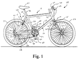
- Bicycle frame 12 has a pair of bicycle brake devices 14 fixedly coupled to frame 12 via brake mounting structures 15 in accordance with a first embodiment of the present invention. While a MTB style bicycle is illustrated, it will be apparent to those skilled in the art from this disclosure that the present invention can be used with other styles of bicycles without departing from the scope of the present invention.
- bicycle frame 12 has a main bicycle frame body 16, which constitutes the skeleton of the bicycle body.
- Bicycle frame body 16 is generally constructed of rigid tubular frame sections or members which are rigidly coupled together by welding or any other conventional method.
- the tubular frame members can be constructed of any suitable rigid material such as aluminum, titanium, etc.
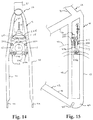
- Bicycle frame 12 also has a front fork 18 constructed mainly of rigid tubular frame members which are rigidly coupled together by welding or any other conventional method. Front fork 18 is rotatably supported by frame body 16 to rotate about an inclined vertical axle in the front portion of frame body 16.
- the bicycle 10 further comprises a handlebar 20 that is fixedly coupled to the front fork 18, a drive train 21 that is attached to the lower portion of the frame body 16 for converting a pedaling force to drive force, a front wheel 22 that is rotatably supported at the lower end of the front fork 18, a rear wheel 23 that is rotatably supported in the back portion of the frame body 16, and front and back braking devices 14.
- the front fork 18 is rotatably coupled at its upper end to frame body 16 and has a bifurcated lower potion for receiving a front wheel 22 therebetween ( Figure 1).
- the front fork 18 has two pairs of rigid tubular frame members 24 with their upper ends coupled together by an intermediate or connecting member 26 and their lower ends joined together by a pair of front wheel mounting ends or plates 27.
- Each of the front wheel mounting ends or plates 27 has an open ended slot 28 for fixedly receiving the axle of the front hub of wheel 22 in a conventional manner.
- the front bicycle brake device 14 is fixedly coupled to front fork 18 via a pair of brake mounting structures 15.
- Each of the brake mounting structures 15 is rigidly and fixedly coupled to a pair of adjacent frame members 24.
- brake mounting structures 15 are welded between frame members 24.
- Brake mounting structures 15 are shown in Figures 6 and 7 and discussed in detail below.
- the handlebar 20 has a handlebar stem adjustably coupled to the top portion of the front fork 18 for adjusting the height of the handlebar, and a pair of handle portions extending to the right and left from the top end of the handlebar stem.
- Grips are fitted on the two ends of the handle portions of the handlebar 20.
- the general construction and operation of brake levers 29 and shifting levers 30 are generally old and well known, and thus, they will not be discussed or illustrated in detail herein.
- the frame body 16 is a diamond shaped frame with a front triangle and a back triangle located behind the front triangle.
- the front triangle comprises a horizontally disposed top tube 31, an angled down tube 32 that is located beneath the top tube 31 and that rises toward the front, a head tube 33 for joining the front ends of the top tube 31 and the down tube 32, and a seat tube 34 that rises at an angle and joins the back ends of the top tube 31 and the down tube 32.
- a bottom bracket shell 35 is formed at the joint between the seat tube 34 and the down tube 32.
- a seat post 36 equipped with a saddle 37 is slideably coupled to the seat tube 34 for vertically adjusting the position of the seat post 36 and saddle 37.
- the back triangle comprises a rear or back fork 40 having a seat stay 41 rigidly coupled to seat tube 34 and a chain stay 42 rigidly coupled to bottom bracket shell 35.
- the seat stay 41 has four rigid tubular frame members 43 with the front ends of each tubular frame members 43 rigidly coupled to seat tube 34.
- the tubular frame members 43 extend downwardly from seat tube 34 in a bifurcated manner for receiving rear wheel 23 therebetween.
- a pair of tubular frame members 43 are located on each side of rear wheel 23.
- the rear ends of adjacent tubular frame members 43 are each interconnected together by a rear fork mounting end or plate 44.
- Each of the rear fork mounting ends or plates 44 has an open ended slot 45 for fixedly receiving the axle of the rear hub in a conventional manner.
- the rear bicycle brake device 14 of the first embodiment is also fixedly coupled to the seat stay 41 via a pair of brake mounting structures 15.
- the front and rear bicycle brake devices 14 are fixedly coupled to frame 12 in substantially the same manner, except for different frame members.
- Each of the brake mounting structures 15 of the rear bicycle brake device 14 is rigidly and fixedly coupled to a pair of adjacent frame members 43.
- brake mounting structures 15 of the rear bicycle brake device 14 are welded to a pair of adjacent frame members 43 as seen in Figure 5.
- chain stay 42 has a pair of rigid tubular frame members 46 with one of the frame members 46 located on each side of wheel rear 23.
- Chain stay 42 has the front ends of tubular frame members 46 rigidly coupled to bottom bracket shell 35 as seen in Figure 1.
- the tubular frame members 46 extend backward from bottom bracket shell 35 where they are joined at their back ends by the rear fork mounting ends or plates 44.
- the drive train 21 basically comprises a front chainwheel and crank assembly 54 coupled to the bottom bracket shell 35, a set of rear chainwheels or sprockets 55 non-rotatably attached to the free hub of rear wheel 23, a chain 56 tat passes over the front chainwheel and crank assembly 54 and rear chainwheels 55, and passes through front and rear deraille 57 and 58 for shifting gears in a conventional manner via shifting levers 30.
- chainwheel and crank assembly 54 comprises a bottom bracket (not shown), right and left crank arms 59, with pedals 60 attached to the tip of each crank arm 59.
- the bottom bracket connects right and left crank arms 59 together.
- a spindle is rotatably supported by the bottom bracket which in turn is mounted in bottom bracket shell 35 of frame body 16 in a conventional manner.
- front bicycle brake device 14 is coupled to front fork 18 for engaging and applying a braking force against the rim of front bicycle wheel 22.
- rear bicycle brake device 14 is coupled to rear fork 40 for engaging and applying a braking force against the rim of rear bicycle wheel 23.
- bicycle brake devices 14 are illustrated as cantilever brake devices.
- Brake devices 14 have an increased braking force over prior art brake devices in that the brake devices 14 are pivotally supported by mounting structures 15 as discussed below.
- Bicycle brake devices 14 are operated in a substantially conventional manner by the rider via conventional brake operating devices or levers 29 which are mounted on handle bar 20 of bicycle 10 in a conventional manner.
- Bicycles and their various components are well-known in the prior art, and thus, bicycle 10 and its various components will not be discussed or illustrated in detail herein.
- brake devices 14 are operatively coupled to brake operating devices 29 via conventional brake cables 62, each having an inner brake wire 63 and an outer casing 64.
- the rider operates one or both of the brake operating devices 29 to cause one or both of the brake devices 14 to move inwardly for applying a braking force against the rim of one or both of the bicycle wheels 22 and/or 23.
- brake devices 14 Upon release of the brake operating devices 29, brake devices 14 will release the rim to allow bicycle wheels 22 and 23 to freely rotate.
- each of the brake devices 14 basically includes a pair of brake mechanisms 70a and 70b which are substantially mirror images of each other, except for their connections to brake cable 62.
- right brake mechanism 70a basically includes a mounting assembly 71a, a brake arm 72a, a return spring 73a, and a brake shoe 75a
- left brake mechanism 70b basically includes a mounting assembly 71b, a brake arm 72b, a return spring 73b and a brake shoe 75b.
- Mounting assemblies 71a and 71b are fixedly coupled to brake mounting structures 15 for fixedly coupling brake device 14 to the tubular frame members of frame 12.
- Brake arms 72a and 72b are preferably constructed of a suitable rigid material.
- the brake arms can be cast or machined from any suitable material such as aluminum, titanium, dense plastic, ceramic, acrylic, etc.
- brake arms 72a and 72b are constructed of a lightweight material to minimize the weight of brake devices 14.
- Brake arms 72a and 72b are substantially identical to each other, except that their upper ends are slightly modified for accommodating conventional cable connections or wire mounting portions as seen in Figures 2 and 4.
- Brake arms 72a and 72b are pivotally coupled to mounting assemblies 71a and 71b, respectively, for movement between a release position and a braking position.
- Return springs 73a and 73b are coupled between mounting assemblies 71a and 71b and brake arms 72a and 72b, respectively, for pivotally biasing brake arms 72a and 72b to their release positions.
- Brake shoes 75a and 75b are fixedly coupled to shoe attachment portions 74a and 74b of brake arms 72a and 72b, respectively.
- Each of the mounting assemblies 71a and 71b are basically identical and include a mounting or pivot pin 80 and a bushing arrangement 81.
- the mounting or pivot pins 80 are each preferably constructed of two pieces, e.g., a bolt 82 and an internally threaded sleeve 83.
- the bushing arrangements 81 surround pivot pins 80 and are fixedly secured to mounting structures 15 via engagement pins 84 as seen in Figure 6. Since pivot pins 80 and bushing arrangements 81 are well-known in the art, they will not be discussed in detail herein.
- Brake arms 72a and 72b have their upper portions 85a and 85b coupled to brake cable 62 for moving brake arms 72a and 72b from a release position to a braking position.
- upper portion 84a of brake arm 72a is coupled to inner brake wire 63 of brake cable 62 via lock bolt 87 which is received into a threaded hole. Lock bolt 87 clamps inner brake wire 63 against upper portion 85a of brake arm 72a.
- the outer casing 64 of brake cable 62 is coupled to upper portion 85b of brake arm 72b by connecting arm 86.
- connecting arm 86 is pivotally coupled to upper portion 85b of brake arm 72b and outer casing 64 of brake cable 62.
- Application of brake operating device 29 causes upper portions 85a and 85b to move inwardly towards each other and the friction pads of brake shoes 75a and/or 75b to engage the rim of the wheels 22 and/or 23.
- shoe attachment portions 74a and 74b integrally formed therewith.
- shoe attachment portions 74a and 74b can be pivotally coupled to brake arms 72a and 72b for attaching brake shoes 75a and 75b thereto in a conventional manner as known in the art.
- other types of shoe attachment portions can be utilized as needed and/or desired.
- brake arms 72a and 72b each have a hole for receiving one of the pivot pins 80 therethrough,
- the lower portions of brake arms 72a and 72b are pivotally coupled to mounting assemblies 71a and 71b such that brake arms 72a and 72b can rotate about the pivot axes formed by pivot pins 80.
- Return spring or biasing member 73a is fixedly coupled at one end to mounting assembly 71 via a fastener or screw in a conventional manner.
- Return spring 73a is designed to normally bias brake arm 72a in a clockwise direction as seen in Figures 2 and 4. Accordingly, brake arm 72a is biased by return spring 73a such that brake shoe 75a normally moves away from the rim of bicycle wheel 22 or 23.
- Return spring or biasing member 73b is similarly designed to normally bias brake arm 72b to a release position. Specifically, brake arm 72b is biased by return spring 73b in a counter-clockwise direction as seen in Figures 2 and 4. Accordingly, brake arm 72b is biased by return spring 73b such that brake shoe 75b normally moves away from the rim of bicycle wheel 22 or 23.
- Brake shoe 75a is attached to shoe attachment portion 74a such that brake shoe 75a can be adjusted vertically to ensure proper engagement between brake shoe 75a and the rim of bicycle wheel 22 or 23.
- brake shoe 75b is attached to shoe attachment portion 74b such that brake shoe 75b can be adjusted vertically to ensure proper engagement between brake shoe 75b and the rim of bicycle wheel 22 or 23.
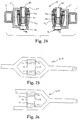
- each bicycle brake mounting structure 15 has an intermediate connecting member 90 and a pair of brake mounting flanges 91 extending substantially perpendicular from opposite ends of an intermediate connecting member 90.
- An attachment flange 92 extends outwardly from each of the mounting flanges 91 for attaching mounting structure 15 to frame members 24 of front fork 18 as seen in Figure 6.
- a mounting recess 94 is formed between flanges 91 and 92 for receiving a tubular frame member.
- brake mounting structure 15 is welded or otherwise rigidly and fixedly secured to the tubular frame members such that the tubular frame members are located within the recesses 94.
- Each of the brake mounting flanges 91 has a pivot mounting hole 95 for receiving one end of the pivot pin 80 for the brake arm.
- the pin mounting holes 95 are preferably axially aligned with one another.
- one of the mounting flanges 91 of each of the mounting structures 15 also has a smaller hole 96 for receiving one of the engagement pins 84 as seen in Figure 6 of the mounting assemblies 71a or 71b.
- brake arm 72a rotates in a counter clockwise direction about pivot pin 80 against the force of return spring 73a and brake arm 72b rotates in a clockwise direction about pivot pin 80 against the force of return spring 73b,
- the inner brake wire 63 of the brake cable 62 is relaxed so that the return springs 73a and 73b cause the brake arms 72a and 72b to pivot in their opening directions.
- the inner faces of the friction pads of brake shoes 75a and 75b are withdrawn from the side surfaces of the rim of the bicycle wheel 22 and/or 23 so that the braking action is released.
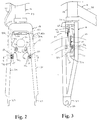
- FIG. 8 and 9 a portion of bicycle frame 12 with a modified front fork 118 is illustrated in accordance with a second embodiment of the present invention.
- This second embodiment differs from the first embodiment in that instead of utilizing a cantilever brake device 14, a side pull type of caliper brake device 114 is used.
- the front fork 118 does not have brake mounting structures 15. Rather, the front fork 118 has been modified such that attachment component 25 directly supports brake device 114.
- the second embodiment utilizes many of the same parts of the first embodiment, these parts will be given the same reference numerals.
- Caliper brake device 114 is a side pull type of caliper brake, and basically comprises a pair of brake arms 172a and 172b pivotally coupled together by a center mounting or pivot pin 180.
- the brake arms 172a and 172b are normally biased by a return spring (not shown) to a release position in which the brake pads of the brake shoes 175a and 175b are spaced from the rim of the front wheel 22.
- each end of the pivot pin 180 is supported by a rigid frame member or section of front fork 118.
- front fork 118 has two pairs of rigid tubular frame members 24 with their upper ends coupled together by a U-shaped attachment component 25, and their lower ends joined together by a pair of front wheel mounting ends or plates 27.
- Each of the front wheel mounting ends or plates 27 has an open ended slot 28 for fixedly receiving the axle of the front hub of wheel 22 in a conventional manner.
- Brake device 114 is fixedly coupled to the U-shaped attachment component 25 by the pivot pin 180.
- the pivot pin 180 is comprised of a nut and bolt arrangement. As seen in Figure 9, both ends of pivot pin 180 is supported by the U-shaped attachment component 25.
- other types of pivot pins could be utilized as needed and/or desired.
- Brake device 114 is operatively coupled to a brake operating device via brake cable 62 which has an inner brake wire 63 and an outer casing 64. Basically, the rider will operate the brake operating device coupled to the handlebar which will in turn cause the brake device 114 to move inwardly to apply a braking force against the rim of the front bicycle wheel 22. Upon release of the brake operating device, brake device 114 will release the rim to allow the bicycle wheel 22 to freely rotate.
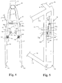
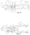
- FIG. 10 a portion of bicycle frame 12 with a modified front fork 218 is illustrated in accordance with a third embodiment of the present invention.
- This third embodiment differs from the first embodiment in that instead of utilizing a cantilever brake device 14, a center pull type of caliper brake device 214 is used by adding a tubular frame member 225 and a single brake mounting stricture 15'.
- a center pull type of caliper brake device 214 is used by adding a tubular frame member 225 and a single brake mounting stricture 15'.
- caliper brake device 214 has a brake arm bridge 271 with a pair of brake arms 272a and 272b pivotally coupled to brake arm bridge 271 by pivot pins 280.
- the brake arm bridge 271 is fixedly coupled to the brake mounting stricture 15' via a center mounting bolt 281.
- the brake arms 272a and 272b are normally biased relative to brake arm bridge 271 by a return spring 273 to a release position. In the release position, the brake pads of the brake shoes 275a and 275b are spaced from the rim of the front wheel 22.
- Brake device 214 is supported by brake mounting structure 15', which in turn is rigidly mounted to rigid tubular frame members 225 of front fork 218. More specifically, similar to the first embodiment, front fork 218 has two pairs of rigid tubular frame members 24 with their upper ends coupled together by a U-shaped attachment component 25, and their lower ends joined together by a pair of front wheel mounting ends or plates 27. Each of the front wheel mounting ends or plates 27 has an open ended slot 28 for fixedly receiving the axle of the front hub of wheel 22 in a conventional manner. However, unlike the first embodiment, front fork 218 also has a frame member 225, which extends between opposite frame members 24. Brake mounting structure 15' is fixedly coupled to frame member 225 by welds or any other suitable method.
- Caliper brake device 214 is a center pull type brake, which is mounted to front fork 218 via a mounting structure 15'.
- Mounting structure 15' is a substantially U-shaped member, which is similar to mounting structure 15 of the first embodiment.
- Brake mounting structure 15' is preferably fixedly and rigidly coupled to frame member 225 of bicycle frame 12.
- bicycle brake mounting structure 15' has an intermediate connecting member and a pair of brake mounting flanges extending substantially perpendicular from opposite ends of an intermediate connecting member.
- Each of the brake mounting flanges has a mounting hole for receiving one end of the mounting pin 281 of the bicycle brake device 214.
- the pin mounting holes are preferably axially aligned with one another.
- a mounting recess is formed between flanges for receiving the brake bridge arm 271 of bicycle brake device 214 therebetween.
- brake mounting structure 15' is welded or otherwise rigidly and fixedly secured to the tubular frame member 225.
- Brake device 214 is operatively coupled to a brake operating device via brake cable 62 which has an inner brake wire 63 and an outer casing 64. Basically, the rider will operate the brake operating device coupled to the handlebar which will in turn cause the brake arms 272a and 272b of brake device 214 to move inwardly to apply a braking force against the rim of the front bicycle wheel 22. Upon release of the brake operating device, brake device 214 will release the rim to allow the bicycle wheel 22 to freely rotate.
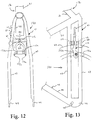
- FIG. 12 the rear fork portion 140 of a modified bicycle frame 12 is illustrated in accordance with a fourth embodiment of the present invention.
- this fourth embodiment differs from the first embodiment in that the seat stay 41 of frame 12 has been modified to support a side pull caliper brake device 114.
- the fourth embodiment utilizes many of the same parts of the first embodiment, these parts will be given the same reference numerals.
- a pair of tubular frame members 115 are coupled to the frame members 43 of the seat stay 41.
- Each of the tubular frame members 115 have an axially aligned hole for receiving pivot or mounting pin 180.
- Pin 180 is preferably a bolt and nut arrangement.
- the frame members 115 are parallel to each other and together form a brake mounting structure.
- frame members 115 basically correspond to brake mounting flanges 91 of brake mounting structure 15.
- Brake device 114 is operatively coupled to a brake operating device via brake cable 62 which has an inner brake wire 63 and an outer casing 64. Basically, the rider will operate the brake operating device coupled to the handlebar which will in turn cause the brake arms 172a and 172b of brake device 114 to move inwardly to apply a braking force against the rim of the rear bicycle wheel 23. Upon release of the brake operating device, brake device 114 will release the rim to allow the bicycle wheel 23 to freely rotate.
- a modified rear fork portion 40 of a bicycle frame 12 is illustrated in accordance with a fifth embodiment of the present invention.
- This fifth embodiment differs from the first embodiment in that the seat stay 41 of frame 12 has been slightly modified to support a center pull caliper brake device 214 in a manner which is similar to the third embodiment.
- the fifth embodiment utilizes many of the same parts of the first and third embodiments, these parts will be given the same reference numerals.
- Caliper brake device 214 is a center pull type brake, which is mounted to the seat stay 41 of the rear fork via a mounting structures 15'.
- caliper brake device 214 basically has a brake arm bridge 271 with a pair of brake arms 272a and 272b pivotally coupled to brake arm bridge 271 by pivot pins 280.
- the brake arm bridge 271 is fixedly coupled to the brake mounting structure 15' via a center mounting bolt 281.
- the brake arms 272a and 272b are normally biased relative to brake arm bridge 271 by a return spring 273 to a release position. In the release position, the brake pads of the brake shoes 275a and 275b are spaced from the rim of the rear wheel 23.
- a brake mounting structure like the one shown in figure 7 can be used with a pair of frame members as needed and/or desired.
- a more conventional front fork can be used to mount brake device 214 thereto in accordance with the present invention.
- Brake device 214 is supported by brake mounting structure 15' to rigid tubular frame member 225 of seat stay 41.
- seat stay 41 has two pairs of rigid tubular frame members 43 with their upper ends coupled seat tube 34, and their lower ends joined together by a pan of front wheel mounting ends or plates 44.
- Each of the rear wheel mounting ends or plates 44 has an open ended slot 45 for fixedly receiving the axle of the rear hub of wheel 23 in a conventional manner.
- seat stay 41 also has a frame member 225, which extends between opposite frame members 43.
- Brake device 214 is operatively coupled to a brake operating device via brake cable 62 which has an inner brake wire 63 and an outer casing 64. Basically, the rider will operate the brake operating device coupled to the handlebar which will in turn cause the brake arms 272a and 272b of brake device 214 to move inwardly to apply a braking force against the rim of the rear bicycle wheel 23. Upon release of the brake operating device, brake device 214 will release the rim to allow the bicycle wheel 23 to freely rotate.
- FIG. 16 and 17 the rear fork portion 140' of a modified bicycle frame 12 is illustrated in accordance with a sixth embodiment of the present invention.
- This sixth embodiment differs from the first embodiment in that the chain stay 142 of frame 12 has been modified to support cantilever brake device 14.
- the first and sixth embodiments will be discussed and illustrated herein.
- the sixth embodiment utilizes many of the same parts of the first and third embodiments, these parts will be given the same reference numerals.
- the chain stay 142 is constructed of four tubular frame members 146 with the front end of each frame member 146 rigidly coupled to the bottom bracket shell 35 by welds.
- the rear ends of two adjacent frame members 146 are coupled together by wheel mounting ends or plates 144.
- the wheel mounting plates 144 have open ended slots 145 for receiving the axle of the rear hub.
- Adjacent pairs of the frame members 146 have mounting structures 15 fixedly coupled thereto for coupling brake device 14 thereto in substantially the same manner as in the first embodiment.
- Brake device 14 is operatively coupled to a brake operating device via brake cable 62 which has an inner brake wire 63 and an outer casing 64. Basically, the rider will operate the brake operating device coupled to the handlebar which will in turn cause the brake device 14 to move inwardly to apply a braking force against the rim of the rear bicycle wheel 23. Upon release of the brake operating device, brake device 14 will release the rim to allow the bicycle wheel 23 to freely rotate.
- FIG. 18 the rear fork portion 140'' of a modified bicycle frame 12 is illustrated in accordance with a seventh embodiment of the present invention, which is similar to the sixth embodiment.
- This seventh embodiment differs from the sixth embodiment in that the chain stay 142 of frame 12 has been modified to support the side pull caliper brake device 114.
- the seventh embodiment utilizes many of the same parts of the first and sixth embodiments, these parts will be given the same reference numerals.
- a pair of tubular frame members 115' are coupled to the frame members 43 of the seat stay 41.
- Each of the tubular members 115' have an axially aligned hole for receiving pivot pin 380.
- the frame members 115' are parallel to each other, and together form a brake mounting structure.
- frame members 115' basically corresponds to brake mounting flanges 91 of brake mounting structure 15.
- Brake device 114 is operatively coupled to a brake operating device via brake cable 62 which has an inner brake wire 63 and an outer casing 64. Basically, the rider will operate the brake operating device coupled to the handlebar which will in turn cause the brake device 114 to move inwardly to apply a braking force against the rim of the rear bicycle wheel 23. Upon release of the brake operating device, brake device 114 will release the rim to allow the bicycle wheel 23 to freely rotate.
- a modified rear fork portion 140 of a bicycle frame 12 is illustrated in accordance with an eighth embodiment of the present invention, which is similar to the sixth embodiment.
- This eighth embodiment differs from the sixth embodiment in that the chain stay 142 of frame 12 has been modified to support a center pull caliper brake device 214 in a manner that is similar to the third embodiment.
- the eighth embodiment utilizes many of the same parts of the first, third and sixth embodiments, these parts will be given the same reference numerals.
- Caliper brake device 214 is a center pull type brake, which is mounted to the chain stay 142 via a mounting structure 15'.
- Caliper brake device 214 has a brake arm bridge 271 with a pair of brake arms 272a and 272b pivotally coupled to brake arm bridge 271 by pivot pins 280.
- the brake arm bridge 271 is fixedly coupled to the brake mounting structure 15' via a center mounting bolt 281.
- the brake arms 272a and 272b are normally biased relative to brake arm bridge 271 by a return spring 273 to a release position. In the release position, the brake pads of the brake shoes 275a and 275b are spaced from the rim of the rear wheel 23.
- Brake device 214 is supported by brake mounting structure 15' to rigid tubular frame member 225 of chain stay 142.
- chain stay 142 has two pairs of rigid tubular frame members 146 with one of their ends coupled to the bottom bracket shell 35, and their other ends joined together by a pair of rear wheel mounting ends or plates 144.
- Each of the rear wheel mounting ends or plates 144 has an open ended slot 145 for fixedly receiving the axle of the rear hub of wheel 23 in a conventional manner.
- front fork 218 also has a frame member 225 which extends between opposite frame members 146.
- a brake mounting structure like the one shown in figure 7 can be used with a pair of frame members as needed and/or desired.
- a more conventional front fork can be used to mount brake device 214 thereto in accordance with the present invention.
- Brake device 214 is operatively coupled to a brake operating device via brake cable 62 which has an inner brake wire 63 and an outer casing 64. Basically, the rider will operate the brake operating device coupled to the handlebar which will in turn cause the brake device 214 to move inwardly to apply a braking force against the rim of the rear bicycle wheel 23. Upon release of the brake operating device, brake device 214 will release the rim to allow the bicycle wheel 23 to freely rotate.
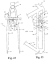
- FIG. 22 and 23 a portion of bicycle frame 12 with a modified rear fork 40 is illustrated in accordance with a ninth embodiment of the present invention.
- This ninth embodiment is similar to the fourth embodiment except that the side pull caliper brake device 114 is attached to frame members 115 via a single bicycle brake mounting 15.
- the ninth embodiment utilizes many of the same parts of the first and fourth embodiments, these parts will be given the same reference numeral.
- a modified brake mounting structure 15' is illustrated in accordance with another variation of the present invention.
- This mounting structure 15' has its intermediate section coupled directly to a tubular frame section 12' for supporting bicycle brake device 14 of the first embodiment in substantially the same manner as discussed in the preceding embodiments which utilizes a brake mounting structure 15.
- This tubular frame section 12' can be part of the front bicycle fork, the seat stay and/or chain stay of a modified bicycle frame. In view of the similarities between this embodiment and the prior embodiments, this tubular frame section 12' will not be discussed or illustrated in detail herein.
- a tubular frame section 313 is illustrated in accordance with another embodiment of the present invention.
- This tubular frame section 313 can be utilized to support a bicycle brake device in substantially the same manner as discussed in the preceding embodiments which utilizes a brake mounting structure 15.
- This tubular frame section can be part of the front bicycle fork, the seat stay and/or chain stay of a modified bicycle frame. In view of the similarities between this embodiment and the prior embodiments, this tubular fork section will not be discussed or illustrated in detail herein.
- a tubular frame section 413 is illustrated in accordance with still another embodiment of the present invention,
- This tubular frame section 413 can be utilized to support a bicycle brake device in substantially the same manner as discussed in the preceding embodiments which utilizes a brake mounting structure 15.
- This tubular frame section can be part of the front bicycle fork, the seat stay and/or chain stay of a modified bicycle frame. In view of the similarities between this embodiment and the prior embodiments, this tubular fork section will not be discussed or illustrated in detail herein.
- a bicycle brake device which is coupled to a bicycle frame section, which includes one or more bicycle brake mounting structures.
- the bicycle frame section can be either a portion of a front fork or rear fork of a bicycle.
- the brake device is preferably a caliper brake device such as a cantilever brake device, a side pull brake device, or a center pull brake device.
- the caliper brake device has a pair of brake arms which are pivotally coupled to either the front fork or rear fork for selectively engaging the rim of the bicycle wheel.
- the bicycle brake mounting structures are U-shaped brackets, which are fixedly coupled to the frame member or members.
- the bicycle brake mounting structures are formed by a pair of separate tubular frame members, which are fixedly coupled top the remainder of the bicycle frame section.
- the bicycle brake mounting structure or structures support both ends of pivot pins, while in the case of center pull brake devices, the bicycle brake mounting structure or structures support both ends of the center mounting pin.
Landscapes
- Engineering & Computer Science (AREA)
- Mechanical Engineering (AREA)
- Braking Arrangements (AREA)
- Motorcycle And Bicycle Frame (AREA)
Priority Applications (1)
| Application Number | Priority Date | Filing Date | Title |
|---|---|---|---|
| EP03021767A EP1375332B1 (de) | 1998-05-27 | 1999-05-26 | Bremsträger für Fahrräder |
Applications Claiming Priority (2)
| Application Number | Priority Date | Filing Date | Title |
|---|---|---|---|
| US84400 | 1998-05-27 | ||
| US09/084,400 US6186529B1 (en) | 1998-05-27 | 1998-05-27 | Bicycle brake mounting structure |
Related Child Applications (1)
| Application Number | Title | Priority Date | Filing Date |
|---|---|---|---|
| EP03021767A Division EP1375332B1 (de) | 1998-05-27 | 1999-05-26 | Bremsträger für Fahrräder |
Publications (3)
| Publication Number | Publication Date |
|---|---|
| EP0960807A2 true EP0960807A2 (de) | 1999-12-01 |
| EP0960807A3 EP0960807A3 (de) | 2003-01-02 |
| EP0960807B1 EP0960807B1 (de) | 2004-12-15 |
Family
ID=22184734
Family Applications (2)
| Application Number | Title | Priority Date | Filing Date |
|---|---|---|---|
| EP99110207A Expired - Lifetime EP0960807B1 (de) | 1998-05-27 | 1999-05-26 | Fahrradrahmenteil mit einem Bremsmontageanordnung |
| EP03021767A Expired - Lifetime EP1375332B1 (de) | 1998-05-27 | 1999-05-26 | Bremsträger für Fahrräder |
Family Applications After (1)
| Application Number | Title | Priority Date | Filing Date |
|---|---|---|---|
| EP03021767A Expired - Lifetime EP1375332B1 (de) | 1998-05-27 | 1999-05-26 | Bremsträger für Fahrräder |
Country Status (6)
| Country | Link |
|---|---|
| US (3) | US6186529B1 (de) |
| EP (2) | EP0960807B1 (de) |
| JP (1) | JP3205733B2 (de) |
| CN (1) | CN1094448C (de) |
| DE (2) | DE69928972T2 (de) |
| TW (1) | TW453966B (de) |
Cited By (2)
| Publication number | Priority date | Publication date | Assignee | Title |
|---|---|---|---|---|
| EP2551178A1 (de) * | 2011-07-29 | 2013-01-30 | Canyon Bicycles GmbH | Fahrradgabel mit Bremseinheit |
| EP2551179A3 (de) * | 2011-07-29 | 2013-09-11 | Canyon Bicycles GmbH | Doppelbrücken-Fahrradgabel |
Families Citing this family (17)
| Publication number | Priority date | Publication date | Assignee | Title |
|---|---|---|---|---|
| DE20202255U1 (de) * | 2002-02-14 | 2003-06-26 | Nicol, Morgan, Montagnola | Fahrradgabel |
| JP4458803B2 (ja) * | 2003-10-14 | 2010-04-28 | 本田技研工業株式会社 | 自動二輪車 |
| US7331429B2 (en) * | 2004-11-22 | 2008-02-19 | Gigantex Composite Technologies Co., Ltd. | Brake for composite rim |
| TWM286174U (en) * | 2005-09-28 | 2006-01-21 | Shang-Ru Tsai | Bicycle frame structure capable of hiding brake |
| EP1862385A1 (de) * | 2006-05-30 | 2007-12-05 | Shang-Ju Tsai | Fahrradstruktur mit verdeckbarer Bremse |
| FR2903650A1 (fr) * | 2006-07-17 | 2008-01-18 | Time Sport Internat Sa | Dispositif de freinage pour roue a jante notamment pour une roue de velo |
| US8096391B2 (en) | 2006-08-10 | 2012-01-17 | Philip White | Fork with integrated braking system |
| US7614634B2 (en) * | 2007-04-13 | 2009-11-10 | Felt Racing, Llc | Aerodynamic time trial bike |
| US7878521B2 (en) * | 2007-04-16 | 2011-02-01 | Trek Bicycle Corporation | Bicycle frame with device cavity |
| US8307954B2 (en) * | 2007-09-05 | 2012-11-13 | Kimori Limited | Caliper brake attachment tool for rear wheel of bicycle |
| JP5878685B2 (ja) * | 2010-05-10 | 2016-03-08 | ▲彦▼豪金属工業股▲ふん▼有限公司 | 後置式空気抵抗の小さいブレーキ装置 |
| US20120112430A1 (en) * | 2010-11-07 | 2012-05-10 | Justin Shaw | Bicycle tire traction device, system and method |
| US20130341129A1 (en) | 2012-06-26 | 2013-12-26 | Shimano Inc. | Bicycle brake arm |
| US9457867B2 (en) | 2013-03-14 | 2016-10-04 | Specialized Bicycle Components, Inc. | Bicycle brake assembly |
| TWI565619B (zh) * | 2015-03-19 | 2017-01-11 | 彥豪金屬工業股份有限公司 | 自行車前叉結構 |
| US10836452B2 (en) * | 2015-09-25 | 2020-11-17 | Honda Motor Co., Ltd. | Front fork for saddled vehicle |
| KR102608296B1 (ko) * | 2022-11-01 | 2023-11-30 | 주식회사 서브루나바이크 | 패드의 위치조절이 용이한 자전거용 림브레이크 |
Family Cites Families (37)
| Publication number | Priority date | Publication date | Assignee | Title |
|---|---|---|---|---|
| US1108932A (en) * | 1912-11-23 | 1914-09-01 | Frederick John Ridgway | Spring-fork for cycles and motor-cycles. |
| GB412373A (en) * | 1933-04-18 | 1934-06-28 | William Henry Whitmill | Clips or like fastening devices, for brake mechanism of cycles, motorcycles or the like |
| GB450429A (en) | 1935-06-12 | 1936-07-17 | Marr Louis Thomas | Improvements in brakes for cycles and the like |
| DE744337C (de) * | 1941-01-03 | 1944-01-14 | Auguste Merlin | Felgenbremse, insbesondere fuer Fahrraeder |
| FR978252A (fr) * | 1948-12-28 | 1951-04-11 | Fourche à arcade pour cycles ou véhicules légers du même genre | |
| GB675533A (en) * | 1949-12-13 | 1952-07-09 | J A Phillips And Company Ltd | Improvements relating to cycle brakes |
| US3776333A (en) * | 1971-09-09 | 1973-12-04 | W Mathauser | Bicycle brake arrangement |
| FR2265603B1 (de) * | 1974-03-29 | 1976-10-08 | Ramond Louis | |
| DE2702541A1 (de) * | 1977-01-21 | 1978-07-27 | Siemens Ag | Antriebsanordnung fuer ein fahrzeug |
| JPS5599988A (en) | 1979-01-24 | 1980-07-30 | Seiko Epson Corp | Liquid crystal composition for dynamic driving |
| JPS5796173A (en) * | 1980-09-29 | 1982-06-15 | Aruuma Shisutemusu Inc | Vertical load supporting frame |
| JPS5766083A (en) * | 1980-10-09 | 1982-04-22 | Honda Motor Co Ltd | Upper fork structure for front fork in autobicycle |
| GB2102749B (en) * | 1981-05-26 | 1985-07-31 | Honda Motor Co Ltd | Motor cycle wheel suspensions |
| US4765443A (en) | 1985-06-03 | 1988-08-23 | Cunningham Charles B | Caliper brake for mountain bicycles having wide tires |
| US5118010A (en) * | 1985-11-20 | 1992-06-02 | Cadbury Schweppes, Plc | In-home drink dispenser |
| DE3614677A1 (de) * | 1986-04-30 | 1987-11-05 | Union Sils Van De Loo & Co | Felgenbremse fuer ein fahrrad |
| EP0290705A1 (de) * | 1987-05-11 | 1988-11-17 | Renato Roatta | Motorrad |
| US4744576A (en) | 1987-06-11 | 1988-05-17 | Scollan Jr Hugh J | Roller board apparatus with independent laterally compliant surface and braking resistance |
| US4770435A (en) * | 1987-06-29 | 1988-09-13 | North America Tradimpex Cycles, Inc. | Freestyle bicycle construction |
| IT1211330B (it) | 1987-09-29 | 1989-10-12 | Campagnolo Spa | Freno per biciclette del tipo a tiro centrale |
| CH678844A5 (de) | 1989-05-18 | 1991-11-15 | Paul Adam | |
| DE69017168T2 (de) * | 1989-12-26 | 1995-06-14 | Shimano Kk | Fahrradbremssteuervorrichtung. |
| US5160205A (en) * | 1991-06-17 | 1992-11-03 | Monarch Marking Systems, Inc. | Thermal printer with adjustable ink ribbon guide roll |
| IT1251294B (it) * | 1991-08-23 | 1995-05-08 | Giampietro Canderle | Ruota motorizzata elettricamente, particolarmente per biciclette, con cambio meccanico incorporato |
| US5222783A (en) * | 1991-12-02 | 1993-06-29 | Lai Soon L | Chair with its backrest adjustable in its angle |
| JP2561412B2 (ja) * | 1992-10-19 | 1996-12-11 | 吉貝機械金属株式会社 | 自転車用制動操作装置 |
| US5499699A (en) | 1994-03-25 | 1996-03-19 | Chen; Tse-Min | Device for locating reinforcing plate of bicycle brake |
| US5626355A (en) * | 1994-04-01 | 1997-05-06 | Voss; Darrell W. | Telescoping-type front fork bicycle suspensions |
| DE9405645U1 (de) | 1994-04-05 | 1994-05-26 | Chen, Tse-Min, Pu-Yen, Changhua | Positionierungseinrichtung für eine Verstärkungsplatte einer Fahrradbremse |
| US5448927A (en) * | 1994-05-03 | 1995-09-12 | Avid Enterprises, Inc. | Adjustable leverage brake lever |
| US5562397A (en) | 1994-07-13 | 1996-10-08 | Clark Equipment Company | Power actuator for attachment plate |
| US5524917A (en) * | 1994-08-03 | 1996-06-11 | Iverson; Leroy P. | Lightweight snowplow dolly |
| US5636716A (en) * | 1995-03-07 | 1997-06-10 | Shimano, Inc. | Bicycle brake device |
| US5531296A (en) * | 1995-04-04 | 1996-07-02 | Liu; Robert Z. | Brake control mechanism for a bicycle |
| DE19526496C2 (de) * | 1995-07-20 | 1998-06-04 | Dietrich Gerhard Ellsaeser | Bremsträger für ein Fahrrad |
| US5562297A (en) * | 1995-12-12 | 1996-10-08 | Lin; Chun-San | Engagement between a connecting element and a front fork |
| US5743284A (en) | 1996-09-18 | 1998-04-28 | Avid Enterprises, Inc. | Cantilever brake with pad attitude control |
-
1998
- 1998-05-27 US US09/084,400 patent/US6186529B1/en not_active Expired - Fee Related
-
1999
- 1999-04-14 TW TW088105976A patent/TW453966B/zh not_active IP Right Cessation
- 1999-04-27 CN CN99105252A patent/CN1094448C/zh not_active Expired - Fee Related
- 1999-05-26 JP JP14590999A patent/JP3205733B2/ja not_active Expired - Fee Related
- 1999-05-26 DE DE69928972T patent/DE69928972T2/de not_active Expired - Fee Related
- 1999-05-26 EP EP99110207A patent/EP0960807B1/de not_active Expired - Lifetime
- 1999-05-26 DE DE69922581T patent/DE69922581T2/de not_active Expired - Fee Related
- 1999-05-26 EP EP03021767A patent/EP1375332B1/de not_active Expired - Lifetime
-
2000
- 2000-10-26 US US09/695,910 patent/US6325401B1/en not_active Expired - Fee Related
-
2001
- 2001-09-28 US US09/964,771 patent/US6572131B2/en not_active Expired - Fee Related
Non-Patent Citations (1)
| Title |
|---|
| None |
Cited By (2)
| Publication number | Priority date | Publication date | Assignee | Title |
|---|---|---|---|---|
| EP2551178A1 (de) * | 2011-07-29 | 2013-01-30 | Canyon Bicycles GmbH | Fahrradgabel mit Bremseinheit |
| EP2551179A3 (de) * | 2011-07-29 | 2013-09-11 | Canyon Bicycles GmbH | Doppelbrücken-Fahrradgabel |
Also Published As
| Publication number | Publication date |
|---|---|
| DE69928972D1 (de) | 2006-01-19 |
| CN1094448C (zh) | 2002-11-20 |
| US20020014756A1 (en) | 2002-02-07 |
| DE69928972T2 (de) | 2006-06-14 |
| DE69922581T2 (de) | 2005-06-09 |
| EP1375332A1 (de) | 2004-01-02 |
| EP0960807B1 (de) | 2004-12-15 |
| US6325401B1 (en) | 2001-12-04 |
| DE69922581D1 (de) | 2005-01-20 |
| JP3205733B2 (ja) | 2001-09-04 |
| US6186529B1 (en) | 2001-02-13 |
| EP1375332B1 (de) | 2005-12-14 |
| CN1236720A (zh) | 1999-12-01 |
| TW453966B (en) | 2001-09-11 |
| EP0960807A3 (de) | 2003-01-02 |
| US6572131B2 (en) | 2003-06-03 |
| JPH11348863A (ja) | 1999-12-21 |
Similar Documents
| Publication | Publication Date | Title |
|---|---|---|
| EP1375332B1 (de) | Bremsträger für Fahrräder | |
| US4768798A (en) | Internal cable arrangement for bicycle frame | |
| US4765443A (en) | Caliper brake for mountain bicycles having wide tires | |
| US7510201B2 (en) | Lever enhanced pedaling system | |
| US7780558B2 (en) | Bicycle rear derailleur | |
| US6024662A (en) | Crank arm set | |
| US6725978B2 (en) | Cable joining system for cycles | |
| US20070191158A1 (en) | Bicycle front derailleur | |
| US20090062045A1 (en) | Bicycle rear derailleur | |
| CN111232119B (zh) | 自行车前拨链器 | |
| US8684386B2 (en) | Head tube assembly for a bicycle with cable access routing in an open steerer configuration | |
| US7152498B2 (en) | Bicycle control cable fixing device | |
| US20130292213A1 (en) | Supplemental mechanism for actuating the brake of a bicycle and methods of use | |
| US4531754A (en) | Radial braking system | |
| EP0891922B1 (de) | Bremsgerät | |
| US5894913A (en) | Bicycle brake assembly | |
| US9334018B2 (en) | Bicycle derailleur | |
| GB2454021A (en) | Bicycle with rear suspension system | |
| EP0791532A2 (de) | Fahrradketten-Radplatte | |
| EP0872410A2 (de) | Fahrradbremsanlage | |
| GB2456315A (en) | Bicycle seat adjustment assembly | |
| US20240199165A1 (en) | Operating device for human-powered vehicle | |
| CN118722937A (zh) | 盘式制动卡钳 | |
| US469630A (en) | Bicycle | |
| WO2006098707A1 (en) | Cable joining system for cycles |
Legal Events
| Date | Code | Title | Description |
|---|---|---|---|
| PUAI | Public reference made under article 153(3) epc to a published international application that has entered the european phase |
Free format text: ORIGINAL CODE: 0009012 |
|
| 17P | Request for examination filed |
Effective date: 19990526 |
|
| AK | Designated contracting states |
Kind code of ref document: A2 Designated state(s): AT BE CH CY DE DK ES FI FR GB GR IE IT LI LU MC NL PT SE |
|
| AX | Request for extension of the european patent |
Free format text: AL;LT;LV;MK;RO;SI |
|
| RIC1 | Information provided on ipc code assigned before grant |
Free format text: 7B 62L 1/14 A, 7B 62L 1/00 B, 7B 62K 21/02 B |
|
| PUAL | Search report despatched |
Free format text: ORIGINAL CODE: 0009013 |
|
| AK | Designated contracting states |
Kind code of ref document: A3 Designated state(s): AT BE CH CY DE DK ES FI FR GB GR IE IT LI LU MC NL PT SE |
|
| AX | Request for extension of the european patent |
Free format text: AL;LT;LV;MK;RO;SI |
|
| 17Q | First examination report despatched |
Effective date: 20030326 |
|
| AKX | Designation fees paid |
Designated state(s): DE FR GB IE IT NL |
|
| GRAP | Despatch of communication of intention to grant a patent |
Free format text: ORIGINAL CODE: EPIDOSNIGR1 |
|
| RTI1 | Title (correction) |
Free format text: BICYCLE FRAME SECTION COMPRISING A BRAKE MOUNTING MEMBER |
|
| GRAS | Grant fee paid |
Free format text: ORIGINAL CODE: EPIDOSNIGR3 |
|
| GRAA | (expected) grant |
Free format text: ORIGINAL CODE: 0009210 |
|
| AK | Designated contracting states |
Kind code of ref document: B1 Designated state(s): DE FR GB IE IT NL |
|
| REG | Reference to a national code |
Ref country code: GB Ref legal event code: FG4D |
|
| REG | Reference to a national code |
Ref country code: IE Ref legal event code: FG4D |
|
| REF | Corresponds to: |
Ref document number: 69922581 Country of ref document: DE Date of ref document: 20050120 Kind code of ref document: P |
|
| PGFP | Annual fee paid to national office [announced via postgrant information from national office to epo] |
Ref country code: GB Payment date: 20050512 Year of fee payment: 7 |
|
| PGFP | Annual fee paid to national office [announced via postgrant information from national office to epo] |
Ref country code: NL Payment date: 20050518 Year of fee payment: 7 |
|
| PGFP | Annual fee paid to national office [announced via postgrant information from national office to epo] |
Ref country code: FR Payment date: 20050519 Year of fee payment: 7 |
|
| PGFP | Annual fee paid to national office [announced via postgrant information from national office to epo] |
Ref country code: IE Payment date: 20050524 Year of fee payment: 7 |
|
| PGFP | Annual fee paid to national office [announced via postgrant information from national office to epo] |
Ref country code: DE Payment date: 20050726 Year of fee payment: 7 |
|
| PLBE | No opposition filed within time limit |
Free format text: ORIGINAL CODE: 0009261 |
|
| STAA | Information on the status of an ep patent application or granted ep patent |
Free format text: STATUS: NO OPPOSITION FILED WITHIN TIME LIMIT |
|
| 26N | No opposition filed |
Effective date: 20050916 |
|
| ET | Fr: translation filed | ||
| PG25 | Lapsed in a contracting state [announced via postgrant information from national office to epo] |
Ref country code: IE Free format text: LAPSE BECAUSE OF NON-PAYMENT OF DUE FEES Effective date: 20060526 Ref country code: GB Free format text: LAPSE BECAUSE OF NON-PAYMENT OF DUE FEES Effective date: 20060526 |
|
| PGFP | Annual fee paid to national office [announced via postgrant information from national office to epo] |
Ref country code: IT Payment date: 20060531 Year of fee payment: 8 |
|
| PG25 | Lapsed in a contracting state [announced via postgrant information from national office to epo] |
Ref country code: NL Free format text: LAPSE BECAUSE OF NON-PAYMENT OF DUE FEES Effective date: 20061201 Ref country code: DE Free format text: LAPSE BECAUSE OF NON-PAYMENT OF DUE FEES Effective date: 20061201 |
|
| GBPC | Gb: european patent ceased through non-payment of renewal fee |
Effective date: 20060526 |
|
| NLV4 | Nl: lapsed or anulled due to non-payment of the annual fee |
Effective date: 20061201 |
|
| REG | Reference to a national code |
Ref country code: IE Ref legal event code: MM4A |
|
| REG | Reference to a national code |
Ref country code: FR Ref legal event code: ST Effective date: 20070131 |
|
| PG25 | Lapsed in a contracting state [announced via postgrant information from national office to epo] |
Ref country code: FR Free format text: LAPSE BECAUSE OF NON-PAYMENT OF DUE FEES Effective date: 20060531 |
|
| PG25 | Lapsed in a contracting state [announced via postgrant information from national office to epo] |
Ref country code: IT Free format text: LAPSE BECAUSE OF NON-PAYMENT OF DUE FEES Effective date: 20070526 |