EP0960048B1 - Nicht-tödliche zugangskontrollvorrichtung - Google Patents
Nicht-tödliche zugangskontrollvorrichtung Download PDFInfo
- Publication number
- EP0960048B1 EP0960048B1 EP98948332A EP98948332A EP0960048B1 EP 0960048 B1 EP0960048 B1 EP 0960048B1 EP 98948332 A EP98948332 A EP 98948332A EP 98948332 A EP98948332 A EP 98948332A EP 0960048 B1 EP0960048 B1 EP 0960048B1
- Authority
- EP
- European Patent Office
- Prior art keywords
- firing
- taser
- personnel
- dart
- lethal
- Prior art date
- Legal status (The legal status is an assumption and is not a legal conclusion. Google has not performed a legal analysis and makes no representation as to the accuracy of the status listed.)
- Expired - Lifetime
Links
- 231100001160 nonlethal Toxicity 0.000 title claims abstract description 14
- 238000010304 firing Methods 0.000 claims description 22
- 230000003213 activating effect Effects 0.000 claims 1
- 230000000149 penetrating effect Effects 0.000 abstract description 2
- 230000000903 blocking effect Effects 0.000 abstract 1
- 230000005484 gravity Effects 0.000 abstract 1
- 238000007493 shaping process Methods 0.000 abstract 1
- 230000001960 triggered effect Effects 0.000 description 8
- 230000006378 damage Effects 0.000 description 7
- 208000027418 Wounds and injury Diseases 0.000 description 6
- 208000014674 injury Diseases 0.000 description 6
- 230000034994 death Effects 0.000 description 5
- 231100000517 death Toxicity 0.000 description 5
- 231100000518 lethal Toxicity 0.000 description 3
- 230000001665 lethal effect Effects 0.000 description 3
- 230000004913 activation Effects 0.000 description 2
- 230000005611 electricity Effects 0.000 description 2
- 238000000034 method Methods 0.000 description 2
- 208000007101 Muscle Cramp Diseases 0.000 description 1
- 208000005392 Spasm Diseases 0.000 description 1
- 241001415801 Sulidae Species 0.000 description 1
- 238000007792 addition Methods 0.000 description 1
- 238000003491 array Methods 0.000 description 1
- 230000009193 crawling Effects 0.000 description 1
- 230000002089 crippling effect Effects 0.000 description 1
- 230000002498 deadly effect Effects 0.000 description 1
- 230000007123 defense Effects 0.000 description 1
- 230000003111 delayed effect Effects 0.000 description 1
- 238000010586 diagram Methods 0.000 description 1
- 230000000694 effects Effects 0.000 description 1
- 238000004146 energy storage Methods 0.000 description 1
- 239000004744 fabric Substances 0.000 description 1
- 238000009434 installation Methods 0.000 description 1
- 230000007774 longterm Effects 0.000 description 1
- 238000012986 modification Methods 0.000 description 1
- 230000004048 modification Effects 0.000 description 1
- 210000003205 muscle Anatomy 0.000 description 1
- 239000000523 sample Substances 0.000 description 1
- 230000009295 sperm incapacitation Effects 0.000 description 1
- 238000009941 weaving Methods 0.000 description 1
Images


Classifications
-
- F—MECHANICAL ENGINEERING; LIGHTING; HEATING; WEAPONS; BLASTING
- F41—WEAPONS
- F41H—ARMOUR; ARMOURED TURRETS; ARMOURED OR ARMED VEHICLES; MEANS OF ATTACK OR DEFENCE, e.g. CAMOUFLAGE, IN GENERAL
- F41H13/00—Means of attack or defence not otherwise provided for
- F41H13/0012—Electrical discharge weapons, e.g. for stunning
- F41H13/0025—Electrical discharge weapons, e.g. for stunning for remote electrical discharge via conducting wires, e.g. via wire-tethered electrodes shot at a target
-
- F—MECHANICAL ENGINEERING; LIGHTING; HEATING; WEAPONS; BLASTING
- F41—WEAPONS
- F41H—ARMOUR; ARMOURED TURRETS; ARMOURED OR ARMED VEHICLES; MEANS OF ATTACK OR DEFENCE, e.g. CAMOUFLAGE, IN GENERAL
- F41H13/00—Means of attack or defence not otherwise provided for
- F41H13/0006—Ballistically deployed systems for restraining persons or animals, e.g. ballistically deployed nets
-
- F—MECHANICAL ENGINEERING; LIGHTING; HEATING; WEAPONS; BLASTING
- F42—AMMUNITION; BLASTING
- F42B—EXPLOSIVE CHARGES, e.g. FOR BLASTING, FIREWORKS, AMMUNITION
- F42B12/00—Projectiles, missiles or mines characterised by the warhead, the intended effect, or the material
- F42B12/02—Projectiles, missiles or mines characterised by the warhead, the intended effect, or the material characterised by the warhead or the intended effect
- F42B12/36—Projectiles, missiles or mines characterised by the warhead, the intended effect, or the material characterised by the warhead or the intended effect for dispensing materials; for producing chemical or physical reaction; for signalling ; for transmitting information
-
- F—MECHANICAL ENGINEERING; LIGHTING; HEATING; WEAPONS; BLASTING
- F42—AMMUNITION; BLASTING
- F42B—EXPLOSIVE CHARGES, e.g. FOR BLASTING, FIREWORKS, AMMUNITION
- F42B8/00—Practice or training ammunition
- F42B8/28—Land or marine mines; Depth charges
-
- H—ELECTRICITY
- H05—ELECTRIC TECHNIQUES NOT OTHERWISE PROVIDED FOR
- H05C—ELECTRIC CIRCUITS OR APPARATUS SPECIALLY DESIGNED FOR USE IN EQUIPMENT FOR KILLING, STUNNING, OR GUIDING LIVING BEINGS
- H05C1/00—Circuits or apparatus for generating electric shock effects
- H05C1/04—Circuits or apparatus for generating electric shock effects providing pulse voltages
Definitions
- the present invention relates generally to a non-lethal device for temporarily disabling personnel. It relates more specifically to a mine-like device that automatically fires a plurality of high voltage probes in a range of directions to effect personnel in proximity to the device but without causing death or permanent disability.
- the present invention employs the well proven non-lethal TASER® weapon and configures it as a non-lethal area denial device, similar to a anti-personnel mine, with multiple independent standoff incapacitation devices that can temporarily incapacitate several subjects without injury when activated by sensors.
- the TASER® device has been proven safe by 18 years of use by over 400 law enforcement agencies and by many studies, including one by the Medical Director of the U.S. Consumer Products Safety Commission.
- the TASER® alternative to the landmine will not cause deaths or injuries if accidentally actuated by friendly forces or innocent civilians.
- the non-lethal TASER® Area Denial Device can be deployed along defensive line perimeters or anti-tank mine fields to prevent enemy reconnaissance troops or small raiding parties from penetrating lines and for their capture. After the Tasered troops are captured the device may be quickly reloaded by field troops for immediate reuse. In the event of a mass attack, the TASER® devices will incapacitate the forward line of the enemy (and any enemy troops that touch the incapacitated troops). The TASER® devices also instill strong fear into any remaining troops due to the human's inherent fear of electricity. This will give "ready troops" time to respond and even counterattack without resistance by the enemy's front line troops.
- the TASER® Area Denial Device can be used to secure storage areas as well as troop facilities and prevent looting or sabotage. It will permit the capture of looters or saboteurs without injury to either the culprit or the security forces.
- the non-lethal TASER® Area Denial Device can also be deployed to keep opposing forces within their assigned areas to prevent conflicts using minimal forces.
- the TASER® devices may also be used to prevent subjects from following forces when they are withdrawing from an area. After the withdrawal is complete the non-lethal TASER® Area Denial Devices may be deactivated from a remote position to prevent accidental triggering by civilians.
- the inventive device comprises a non-lethal alternative to the anti-personnel landmine.
- the TASER® alternative uses electronic stun capability in combination with a landmine housing and deployment system.
- the device can cover a radius of 15 feet (30 feet possible) and can be triggered by various sensors.
- the TASER® device would cause no deaths or injuries if accidentally triggered by friendly forces, it can also be permanently disabled when no longer needed, by remotely using a secure code to shut down the TASER ® system.
- the device When triggered, the device launches darts in multiple directions at 10 or 20 degree intervals in a direction generally facing the enemy.
- the darts temporarily incapacitate any persons within an inch of the darts by causing uncontrollable spasms of the near surface motor control muscles causing temporary loss of the subject's motor control functions. The subject will fall and temporarily be completely incapacitated.
- the device will take down persons wearing soft body armor because high voltage electricity readily arcs through the fabric weaving holes.
- a timing circuit keeps the subjects incapacitated until they can be taken into custody by nearby troops. After the very low power signal is turned off, the subject will recover within minutes.
- the TASER® device produces no collateral damage and poses no lethal threat to friendly forces even if accidentally triggered.
- the device may be remotely shut down permanently via an encrypted security code.
- the conventional, hand-held TASER® device has been proven safe and effective in over 18 years of police use by more than 400 major law enforcement agencies in the United States.
- the TASER® is used by universities such as University of Southern California, Duke University, University of Cincinnati, Black Hawk College and by many airports. It is also used by the U.S. Department of Justice to protect their Washington D.C. headquarters.
- the firing bays 20 are set 20 degrees apart over a 120 degree minimum area toward the expected threat.
- Separate TASER® circuits 16 are centrally mounted and the batteries mounted on the bottom surface.
- the firing bays are arranged so that the upper dart rises one foot for each five feet of range for a short range unit and 1 foot for each ten feet of range in long range units (FIG. 2).
- the lower dart from each firing bay is fired straight out horizontally.
- the firing bay is angled slightly so that the lower dart hits at a height of about 1 - 1.5 feet at a 15 foot range.
- the negative lead is angled to reach a height of 4.5 feet at 15 feet.
- the negative lead is connected to an electrode imbedded in the ground (earth). This connection provides a contact path from either the'upper dart (negative) to the lower dart (positive) or from the lower dart to earth (negative) increasing the take down rate.
- the devices can take down a crawling soldier (from earth to a single positive dart) or a standing soldier (from positive dart to upper negative dart). A standing or crouching soldier could also be taken down between earth and the positive dart even if the upper dart misses.
- the device could take down multiple subjects that' approach at the same time. The subject is disabled for the duration of the applied power plus a few minutes after the power is turned off. Therefore, long life batteries controlling the TASER ® circuit are configured to run for a minimum of 10 minutes (variable depending on battery size), with 1 second breaks every 10 seconds to allow the subject to breath freely under worst case conditions.
- the activation circuit 22 when triggered, sends an alarm signal to nearby troops when triggered.
- the signal indicates the device's coordinates.
- the TASER® system does not have to touch or penetrate a person's skin.
- the electrical pulse generated at the high voltage transformer 18, will easily arc through more than an inch of clothing or the weave of soft body armor.
- the TASER® device may be activated by various low cost methods, such as infrared motion detector, trip wires, pressure plates or a combination of two or more of these methods.
- a 30 foot range system may also be implemented.
- Long range or high density devices may be assembled by stacking two 2-3 inch thick 20 degree deployment TASER® discs so that one disc is automatically offset radially by 10 degrees to provide twice the number of dart sets, each offset by 10 degrees from the next dart set.
- the non-lethal TASER® device While more expensive than crude landmines initially, the non-lethal TASER® device is field reloadable after use and can be used repetitively for years. This capability reduces the number of devices required, reducing the long term overall cost.
- A.remote alarm signal carrying the device's coordinate code is transmitted via radio or satellite to a central site when the device is triggered.
- the signal identifies the location of activation for nearby troops.
- Troops may respond to the alarm to secure the area and take Tasered prisoners.
- the alarm circuitry can also be utilized by the controlling troops to remotely control the TASER® device via secure encrypted codes. After securing prisoners, the TASER® device can be quickly reloaded in the field. The TASER® device may be permanently deactivated when no longer needed, using secure codes.
- the TASER® area denial device may also be used to replace manned guard towers in fixed installations. Dummy units positioned among an array of live devices could also be utilized to reduce costs.
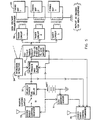
- Radio Control Receiver (33) If a properly coded radio signal is received by the Radio Control Receiver (33) it will remove power from the Power on Relay's coil disarming the device and making it safe to handle.
- the Intrusion Sensor (34) When armed, as noted above and the Intrusion Sensor (34) senses an intruder in any area within 80 percent of the device's maximum range, it will signal the "Intrusion Trigger and Alarm Circuit" (22).
- the Intrusion Trigger and Alarm Circuit (22) will send a coded alarm signal with the device's coordinates to nearby troops via Radio Control Transmitter (36).
- the Intrusion Trigger and Alarm Circuit will also trigger Cycle Timing Circuit (37).
- the Cycle Timing Circuit (37) once triggered, will continually apply power to the TASER® Circuits (36) for 8 seconds out of every 9-10 seconds.
- the first application of power to the TASER® Circuit (16) will immediately cause all of the Firing Bays (20) to simultaneously fire their respective cartridges sending their darts out at various angles toward the intruders.
- the TASER® Circuits (16) When power is applied to them, the TASER® Circuits (16) will each generate an independent oscillator output pulse of 4-8 microseconds duration repeated 10-25 times per second. The energy of this output is limited to less than 0.4 Joules by the energy storage of the oscillator transformer.
- each TASER® Circuit (16) is then stepped up by High Voltage Transformer (18) to 50,000 to 60,000 volts.
- Firing Bay (20) The output of High Voltage Transformer (18) is applied to Firing Bay (20).
- the Firing Bays are each loaded with a standard police TASER ® cartridge.
- the firing bays are located on the edge of the device facing the intruders or enemy. They are set over about a 120 degree angle facing the area of intrusion. Independent circuits and firing bays are used to limit the power if only one subject is hit and to prevent losing power if a set of darts, that did not hit a subject, short circuits: The number of circuits and firing bays used depends on the coverage desired with seven being typical for short ranges and fourteen for longer range.
- Lo Battery Sensor (31) sends a warning to the nearby troops via the Radio Control Transmitter (36) when the battery is approaching depletion.
Landscapes
- Engineering & Computer Science (AREA)
- General Engineering & Computer Science (AREA)
- Radar, Positioning & Navigation (AREA)
- Remote Sensing (AREA)
- Insects & Arthropods (AREA)
- Combustion & Propulsion (AREA)
- Ocean & Marine Engineering (AREA)
- Life Sciences & Earth Sciences (AREA)
- Chemical & Material Sciences (AREA)
- Emergency Alarm Devices (AREA)
- Aiming, Guidance, Guns With A Light Source, Armor, Camouflage, And Targets (AREA)
- Burglar Alarm Systems (AREA)
- Vehicle Body Suspensions (AREA)
- Knitting Machines (AREA)
- Air Bags (AREA)
- Bidet-Like Cleaning Device And Other Flush Toilet Accessories (AREA)
- Emergency Lowering Means (AREA)
- Alarm Systems (AREA)
Claims (7)
- Nicht letale Personenabwehrvorrichtung (10) zum Erfassen von in der Nähe befindlichen Personen und automatischen Abfeuern einer Vielzahl von elektrischen Entladungsprojektilen auf diese Personen, um diese vorübergehend außer Gefecht zu setzen; wobei die Vorrichtung (10) Folgendes umfasst:ein Gehäuse (12) mit einer Vielzahl von Schießbuchten (20), wobei jede Bucht (20) mindestens ein Projektil und ein Antriebsmaterial zum selektiven Abfeuern des Projektils in eine vorherbestimmte Richtung aufweist;eine Vielzahl von Hochspannungstransformatoren (18), wobei jeder Transformator (18) mit Hilfe eines Drahts, mit dem das Projektil nach dem Abfeuern verbunden bleibt, mit mindestens einem Projektil elektrisch verbunden ist; undMittel (34, 22) zum Erfassen von in der Nähe befindlichen Personen und zum Aktivieren der Schießbuchten, um die Projektile abzufeuern und eine Hochspannungsentladung anzulegen, um die in der Nähe befindlichen Personen außer Gefecht zu setzen.
- Vorrichtung nach Anspruch 1, wobei das Gehäuse (12) als Zylinder geformt ist, der eine Höhe aufweist, die geringer als der Durchmesser des Zylinders ist.
- Vorrichtung nach Anspruch 2, wobei die Schießbuchten (20) entlang eines Sektors des Zylinders in ausgewählten Winkelabständen positioniert sind.
- Vorrichtung nach Anspruch 2, wobei die Winkelabstände von einer Schießbucht zur nächsten Schießbucht etwa 20 Grad betragen.
- Vorrichtung nach Anspruch 1, wobei jede der Schießbuchten (20) eine Kartusche aufweist, die zwei der Projektile enthält.
- Vorrichtung nach Anspruch 5, wobei jedes der beiden Projektile in jeder Schießbucht (20) so konfiguriert ist, dass es mit einem unterschiedlichen Höhenwinkel im Verhältnis zum Gehäuse (12) abgefeuert wird.
- Vorrichtung nach Anspruch 1, wobei das Mittel (34) zur Erfassung von in der Nähe befindlichen Personen einen Infrarot-Bewegungsdetektor umfasst.
Applications Claiming Priority (3)
| Application Number | Priority Date | Filing Date | Title |
|---|---|---|---|
| US991268 | 1997-12-16 | ||
| US08/991,268 US5936183A (en) | 1997-12-16 | 1997-12-16 | Non-lethal area denial device |
| PCT/US1998/019514 WO1999030968A1 (en) | 1997-12-16 | 1998-09-17 | Non-lethal area denial device |
Publications (3)
| Publication Number | Publication Date |
|---|---|
| EP0960048A1 EP0960048A1 (de) | 1999-12-01 |
| EP0960048A4 EP0960048A4 (de) | 2000-01-05 |
| EP0960048B1 true EP0960048B1 (de) | 2004-02-04 |
Family
ID=25537040
Family Applications (1)
| Application Number | Title | Priority Date | Filing Date |
|---|---|---|---|
| EP98948332A Expired - Lifetime EP0960048B1 (de) | 1997-12-16 | 1998-09-17 | Nicht-tödliche zugangskontrollvorrichtung |
Country Status (5)
| Country | Link |
|---|---|
| US (3) | US5936183A (de) |
| EP (1) | EP0960048B1 (de) |
| AT (1) | ATE258874T1 (de) |
| DE (1) | DE69821468T2 (de) |
| WO (1) | WO1999030968A1 (de) |
Families Citing this family (63)
| Publication number | Priority date | Publication date | Assignee | Title |
|---|---|---|---|---|
| US5936183A (en) * | 1997-12-16 | 1999-08-10 | Barnet Resnick | Non-lethal area denial device |
| EP0993403A4 (de) | 1998-04-13 | 2004-09-01 | Resnick Barnet | Automatisch zielende, nicht tötliche flächenschutzvorrichtung |
| US6053088A (en) * | 1998-07-06 | 2000-04-25 | Mcnulty, Jr.; James F. | Apparatus for use with non-lethal, electrical discharge weapons |
| US7075770B1 (en) | 1999-09-17 | 2006-07-11 | Taser International, Inc. | Less lethal weapons and methods for halting locomotion |
| US6636412B2 (en) * | 1999-09-17 | 2003-10-21 | Taser International, Inc. | Hand-held stun gun for incapacitating a human target |
| US20040237762A1 (en) * | 1999-11-03 | 2004-12-02 | Metal Storm Limited | Set defence means |
| US6575073B2 (en) * | 2000-05-12 | 2003-06-10 | Mcnulty, Jr. James F. | Method and apparatus for implementing a two projectile electrical discharge weapon |
| US6553912B2 (en) | 2001-04-09 | 2003-04-29 | Blackpoint Engineering, Llc | War games land mine |
| AUPR772101A0 (en) * | 2001-09-17 | 2001-10-11 | Hodgkinson, Ian Andrew | Security monitoring and enforcement system |
| US6679180B2 (en) | 2001-11-21 | 2004-01-20 | Southwest Research Institute | Tetherless neuromuscular disrupter gun with liquid-based capacitor projectile |
| US20030159572A1 (en) * | 2002-02-27 | 2003-08-28 | Richard Downs | Method and apparatus of immobilizing an unauthorized intruder to a secure area |
| US6640721B1 (en) | 2002-08-01 | 2003-11-04 | The United States Of America As Represented By The Secretary Of The Navy | Non-lethal airbag munition |
| US20050188827A1 (en) * | 2002-09-09 | 2005-09-01 | Mcnulty James F.Jr. | Electrical discharge weapon for use as a forend grip of rifles |
| US7145762B2 (en) * | 2003-02-11 | 2006-12-05 | Taser International, Inc. | Systems and methods for immobilizing using plural energy stores |
| US7042696B2 (en) | 2003-10-07 | 2006-05-09 | Taser International, Inc. | Systems and methods using an electrified projectile |
| AU2004317086B8 (en) * | 2003-10-07 | 2008-03-06 | Axon Enterprise, Inc. | Systems and methods for immobilization using charge delivery |
| US7602597B2 (en) * | 2003-10-07 | 2009-10-13 | Taser International, Inc. | Systems and methods for immobilization using charge delivery |
| US7640839B2 (en) * | 2003-11-21 | 2010-01-05 | Mcnulty Jr James F | Method and apparatus for improving the effectiveness of electrical discharge weapons |
| US7520081B2 (en) * | 2004-07-13 | 2009-04-21 | Taser International, Inc. | Electric immobilization weapon |
| US7111559B1 (en) | 2004-07-15 | 2006-09-26 | Maclachlan Edward K | Mobile electrical device for disabling a moving vehicle |
| US20070028501A1 (en) * | 2004-07-23 | 2007-02-08 | Fressola Alfred A | Gun equipped with camera |
| US20060067026A1 (en) * | 2004-09-30 | 2006-03-30 | Kaufman Dennis R | Stun gun |
| US20060086032A1 (en) * | 2004-10-27 | 2006-04-27 | Joseph Valencic | Weapon and input device to record information |
| SE0500043D0 (sv) | 2005-01-10 | 2005-01-10 | Delaval Holding Ab | A milking arrangement |
| US7314007B2 (en) * | 2005-02-18 | 2008-01-01 | Li Su | Apparatus and method for electrical immobilization weapon |
| US7218501B2 (en) * | 2005-06-22 | 2007-05-15 | Defense Technology Corporation Of America | High efficiency power supply circuit for an electrical discharge weapon |
| US7237352B2 (en) * | 2005-06-22 | 2007-07-03 | Defense Technology Corporation Of America | Projectile for an electrical discharge weapon |
| US20070051233A1 (en) * | 2005-09-06 | 2007-03-08 | Duge Robert T | Radiant electromagnetic energy management |
| US9025304B2 (en) | 2005-09-13 | 2015-05-05 | Taser International, Inc. | Systems and methods for a user interface for electronic weaponry |
| WO2008030243A2 (en) * | 2005-09-13 | 2008-03-13 | Taser International, Inc. | Systems and methods for multiple function electronic weaponry |
| US20070214993A1 (en) | 2005-09-13 | 2007-09-20 | Milan Cerovic | Systems and methods for deploying electrodes for electronic weaponry |
| US7778004B2 (en) * | 2005-09-13 | 2010-08-17 | Taser International, Inc. | Systems and methods for modular electronic weaponry |
| US8561516B2 (en) * | 2006-02-21 | 2013-10-22 | Engineering Science Analysis Corporation | System and method for non-lethal vehicle restraint |
| US7986506B2 (en) * | 2006-05-03 | 2011-07-26 | Taser International, Inc. | Systems and methods for arc energy regulation and pulse delivery |
| US7849624B2 (en) * | 2006-05-23 | 2010-12-14 | Taser International, Inc. | Systems and methods for qualified registration |
| US8166693B2 (en) * | 2006-05-23 | 2012-05-01 | Taser International, Inc. | Systems and methods for conditional use of a product |
| US7905180B2 (en) | 2006-06-13 | 2011-03-15 | Zuoliang Chen | Long range electrified projectile immobilization system |
| WO2008005360A2 (en) * | 2006-06-30 | 2008-01-10 | Genesis Illuminations, Inc. | Incapacitating high intensity incoherent light beam |
| US8567980B2 (en) | 2006-06-30 | 2013-10-29 | Todd Eisenberg | Incapacitating high intensity incoherent light beam |
| US7886648B2 (en) * | 2006-10-07 | 2011-02-15 | Kevin Williams | Systems and methods for area denial |
| US7856929B2 (en) | 2007-06-29 | 2010-12-28 | Taser International, Inc. | Systems and methods for deploying an electrode using torsion |
| US7984676B1 (en) | 2007-06-29 | 2011-07-26 | Taser International, Inc. | Systems and methods for a rear anchored projectile |
| US8245617B2 (en) * | 2007-08-07 | 2012-08-21 | Engineering Science Analysis Corporation | Non-lethal restraint device with diverse deployability applications |
| US8601928B2 (en) * | 2007-08-07 | 2013-12-10 | Engineering Science Analysis Corp. | Restraint device for use in an aquatic environment |
| US8336462B2 (en) * | 2008-03-23 | 2012-12-25 | Sdi - Security Device International Inc. | Autonomous operation of a non-lethal projectile |
| US10354689B2 (en) | 2008-04-06 | 2019-07-16 | Taser International, Inc. | Systems and methods for event recorder logging |
| US20090251311A1 (en) * | 2008-04-06 | 2009-10-08 | Smith Patrick W | Systems And Methods For Cooperative Stimulus Control |
| US8166690B2 (en) | 2008-04-30 | 2012-05-01 | Taser International, Inc. | Systems and methods for indicating properties of a unit for deployment for electronic weaponry |
| US7966763B1 (en) | 2008-05-22 | 2011-06-28 | The United States Of America As Represented By The Secretary Of The Navy | Targeting system for a projectile launcher |
| US7952850B1 (en) | 2008-12-30 | 2011-05-31 | Taser International, Inc. | Systems and methods for an electronic demotivator having a recovery switch |
| US8403672B2 (en) | 2009-10-21 | 2013-03-26 | Tim Odorisio | Training target for an electronically controlled weapon |
| KR20140032027A (ko) * | 2012-09-03 | 2014-03-14 | 한국전자통신연구원 | 지능형 지뢰 장치와 그 동작 방법 |
| US10874095B1 (en) * | 2016-01-07 | 2020-12-29 | Edna Brown | Motion sensing animal stun device |
| RU2627878C1 (ru) * | 2016-07-13 | 2017-08-14 | Анатолий Павлович Ефимочкин | Способ уничтожения военных подразделений противника в лесном массиве |
| CN106767179B (zh) * | 2017-01-03 | 2018-09-11 | 上海量明科技发展有限公司 | 飞行式抛靶监测装置及监测方法 |
| RU2718179C2 (ru) * | 2017-12-04 | 2020-03-31 | Габлия Юрий Александрович | Электрошоковая мина направленного действия |
| US10726708B2 (en) | 2018-05-31 | 2020-07-28 | The United States Of America, As Represented By The Secretary Of The Navy | Automatic gunshot detection and suppression response system |
| WO2020162997A2 (en) | 2018-11-09 | 2020-08-13 | Convey Technology, Inc. | Pressure and heat conducted energy device and method |
| US11994369B2 (en) | 2019-01-18 | 2024-05-28 | Axon Enterprise, Inc. | Vehicle with a conducted electrical weapon |
| WO2020236761A2 (en) | 2019-05-16 | 2020-11-26 | Convey Technology, Inc. | Proportional-response conductive energy weapon and method |
| RU2717272C1 (ru) * | 2019-10-29 | 2020-03-19 | Александр Георгиевич Семенов | Охранная система с электрошоковыми минами нелетального действия |
| US12181254B2 (en) * | 2021-04-26 | 2024-12-31 | The United States Of America, As Represented By The Secretary Of The Navy | Active shooter monitoring and incapacitation system |
| US20250305801A1 (en) * | 2024-04-02 | 2025-10-02 | Ghaleb Ayed | Robotic threat mitigation device |
Family Cites Families (13)
| Publication number | Priority date | Publication date | Assignee | Title |
|---|---|---|---|---|
| DE1564769B1 (de) * | 1965-12-06 | 1971-03-25 | Kunio Shimizu | Geraet zum Ausueben eines Elektroschocks im menschlichen Koerper |
| US3803463A (en) * | 1972-07-10 | 1974-04-09 | J Cover | Weapon for immobilization and capture |
| US4253132A (en) * | 1977-12-29 | 1981-02-24 | Cover John H | Power supply for weapon for immobilization and capture |
| DE3538785A1 (de) * | 1985-10-31 | 1987-05-07 | Diehl Gmbh & Co | Mine mit weck- und ausloesesensoren |
| FR2677750B1 (fr) * | 1991-06-11 | 1993-09-03 | Giat Ind Sa | Mine a fils pieges. |
| US5456157A (en) * | 1992-12-02 | 1995-10-10 | Computing Devices Canada Ltd. | Weapon aiming system |
| US5379676A (en) * | 1993-04-05 | 1995-01-10 | Contraves Usa | Fire control system |
| US5473501A (en) * | 1994-03-30 | 1995-12-05 | Claypool; James P. | Long range electrical stun gun |
| US5654867A (en) * | 1994-09-09 | 1997-08-05 | Barnet Resnick | Immobilization weapon |
| US5685636A (en) * | 1995-08-23 | 1997-11-11 | Science And Engineering Associates, Inc. | Eye safe laser security device |
| US5675103A (en) * | 1996-02-08 | 1997-10-07 | Herr; Jan Eric | Non-lethal tetanizing weapon |
| US5786546A (en) * | 1996-08-29 | 1998-07-28 | Simson; Anton K. | Stungun cartridge |
| US5936183A (en) * | 1997-12-16 | 1999-08-10 | Barnet Resnick | Non-lethal area denial device |
-
1997
- 1997-12-16 US US08/991,268 patent/US5936183A/en not_active Expired - Fee Related
-
1998
- 1998-04-13 US US09/059,028 patent/US5955695A/en not_active Expired - Lifetime
- 1998-09-17 AT AT98948332T patent/ATE258874T1/de not_active IP Right Cessation
- 1998-09-17 WO PCT/US1998/019514 patent/WO1999030968A1/en not_active Ceased
- 1998-09-17 EP EP98948332A patent/EP0960048B1/de not_active Expired - Lifetime
- 1998-09-17 DE DE69821468T patent/DE69821468T2/de not_active Expired - Lifetime
-
1999
- 1999-06-08 US US09/327,595 patent/US6269726B1/en not_active Expired - Lifetime
Also Published As
| Publication number | Publication date |
|---|---|
| WO1999030968A1 (en) | 1999-06-24 |
| US5936183A (en) | 1999-08-10 |
| EP0960048A1 (de) | 1999-12-01 |
| EP0960048A4 (de) | 2000-01-05 |
| US6269726B1 (en) | 2001-08-07 |
| DE69821468D1 (de) | 2004-03-11 |
| ATE258874T1 (de) | 2004-02-15 |
| US5955695A (en) | 1999-09-21 |
| DE69821468T2 (de) | 2004-12-02 |
Similar Documents
| Publication | Publication Date | Title |
|---|---|---|
| EP0960048B1 (de) | Nicht-tödliche zugangskontrollvorrichtung | |
| EP0881460B1 (de) | Elektroschock generierende Waffe | |
| US7891128B2 (en) | Systems and methods for local and remote stun functions in electronic weaponry | |
| KR100989530B1 (ko) | 전자식 무기를 위한 전개 유닛 | |
| EP1671406A2 (de) | Ein elektrifiziertes projektil verwendende systeme und verfahren | |
| US20130206028A1 (en) | Area Denial Device | |
| RU2365857C2 (ru) | Система защиты границы охраняемой территории | |
| MXPA02004425A (es) | Dispositivo de defensa instalado. | |
| US9784546B2 (en) | Area denial system | |
| RU2288421C1 (ru) | Магнитно-импульсное метательное устройство | |
| EP0993403A1 (de) | Automatisch zielende, nicht tötliche flächenschutzvorrichtung | |
| McNulty | Advances in nonlethal electronic weaponry | |
| RU2764318C1 (ru) | Способ воздействия на цель и устройство для его осуществления | |
| RU2802640C1 (ru) | Стреляющая электрошоковая мина | |
| US9032878B1 (en) | Obscurant generating, ground-based, networked munition | |
| Daruka | Bombers, Wires and Explosives Part II.–Death Arrives With Us | |
| RU2688498C2 (ru) | Беспилотный взрывомагнитный комплекс | |
| Dahl | New Technologies in Counter-Terrorism and Counter-Insurgency Operations | |
| Panescu | Design and Medical Safety of Neuromuscular Incapacitation Devices [Emerging Technologies] | |
| HK1106957B (en) | Deployment unit for electronic weaponry | |
| JPH11337296A (ja) | 不動化及び捕獲のための改良された武器 |
Legal Events
| Date | Code | Title | Description |
|---|---|---|---|
| PUAI | Public reference made under article 153(3) epc to a published international application that has entered the european phase |
Free format text: ORIGINAL CODE: 0009012 |
|
| 17P | Request for examination filed |
Effective date: 19990818 |
|
| AK | Designated contracting states |
Kind code of ref document: A1 Designated state(s): AT BE CH DE DK ES FI FR GB GR IE IT LI NL PT SE |
|
| RIC1 | Information provided on ipc code assigned before grant |
Free format text: 6B 64D 1/04 A, 6F 42B 12/36 B |
|
| A4 | Supplementary search report drawn up and despatched |
Effective date: 19991117 |
|
| AK | Designated contracting states |
Kind code of ref document: A4 Designated state(s): AT BE CH DE DK ES FI FR GB GR IE IT LI NL PT SE |
|
| GRAH | Despatch of communication of intention to grant a patent |
Free format text: ORIGINAL CODE: EPIDOS IGRA |
|
| GRAS | Grant fee paid |
Free format text: ORIGINAL CODE: EPIDOSNIGR3 |
|
| GRAA | (expected) grant |
Free format text: ORIGINAL CODE: 0009210 |
|
| AK | Designated contracting states |
Kind code of ref document: B1 Designated state(s): AT BE CH DE DK ES FI FR GB GR IE IT LI NL PT SE |
|
| PG25 | Lapsed in a contracting state [announced via postgrant information from national office to epo] |
Ref country code: NL Free format text: LAPSE BECAUSE OF FAILURE TO SUBMIT A TRANSLATION OF THE DESCRIPTION OR TO PAY THE FEE WITHIN THE PRESCRIBED TIME-LIMIT Effective date: 20040204 Ref country code: FI Free format text: LAPSE BECAUSE OF FAILURE TO SUBMIT A TRANSLATION OF THE DESCRIPTION OR TO PAY THE FEE WITHIN THE PRESCRIBED TIME-LIMIT Effective date: 20040204 Ref country code: AT Free format text: LAPSE BECAUSE OF FAILURE TO SUBMIT A TRANSLATION OF THE DESCRIPTION OR TO PAY THE FEE WITHIN THE PRESCRIBED TIME-LIMIT Effective date: 20040204 |
|
| REG | Reference to a national code |
Ref country code: GB Ref legal event code: FG4D |
|
| REG | Reference to a national code |
Ref country code: CH Ref legal event code: EP |
|
| REG | Reference to a national code |
Ref country code: IE Ref legal event code: FG4D |
|
| REF | Corresponds to: |
Ref document number: 69821468 Country of ref document: DE Date of ref document: 20040311 Kind code of ref document: P |
|
| PG25 | Lapsed in a contracting state [announced via postgrant information from national office to epo] |
Ref country code: SE Free format text: LAPSE BECAUSE OF FAILURE TO SUBMIT A TRANSLATION OF THE DESCRIPTION OR TO PAY THE FEE WITHIN THE PRESCRIBED TIME-LIMIT Effective date: 20040504 Ref country code: GR Free format text: LAPSE BECAUSE OF FAILURE TO SUBMIT A TRANSLATION OF THE DESCRIPTION OR TO PAY THE FEE WITHIN THE PRESCRIBED TIME-LIMIT Effective date: 20040504 Ref country code: DK Free format text: LAPSE BECAUSE OF FAILURE TO SUBMIT A TRANSLATION OF THE DESCRIPTION OR TO PAY THE FEE WITHIN THE PRESCRIBED TIME-LIMIT Effective date: 20040504 |
|
| PG25 | Lapsed in a contracting state [announced via postgrant information from national office to epo] |
Ref country code: ES Free format text: LAPSE BECAUSE OF FAILURE TO SUBMIT A TRANSLATION OF THE DESCRIPTION OR TO PAY THE FEE WITHIN THE PRESCRIBED TIME-LIMIT Effective date: 20040515 |
|
| NLV1 | Nl: lapsed or annulled due to failure to fulfill the requirements of art. 29p and 29m of the patents act | ||
| PG25 | Lapsed in a contracting state [announced via postgrant information from national office to epo] |
Ref country code: IE Free format text: LAPSE BECAUSE OF NON-PAYMENT OF DUE FEES Effective date: 20040917 |
|
| ET | Fr: translation filed | ||
| PLBE | No opposition filed within time limit |
Free format text: ORIGINAL CODE: 0009261 |
|
| STAA | Information on the status of an ep patent application or granted ep patent |
Free format text: STATUS: NO OPPOSITION FILED WITHIN TIME LIMIT |
|
| 26N | No opposition filed |
Effective date: 20041105 |
|
| REG | Reference to a national code |
Ref country code: CH Ref legal event code: PUE Owner name: TASER INTERNATIONAL, INC. Free format text: RESNICK, BARNET#SUITE 900, 4400 MACARTHUR BOULEVARD#NEWPORT BEACH, CA 92660 (US) -TRANSFER TO- TASER INTERNATIONAL, INC.#7860 EAST MCCLAIN DRIVE, STE 2#SCOTTSDALE, AZ 85260 (US) |
|
| REG | Reference to a national code |
Ref country code: IE Ref legal event code: MM4A Ref country code: GB Ref legal event code: 732E |
|
| REG | Reference to a national code |
Ref country code: CH Ref legal event code: NV Representative=s name: ISLER & PEDRAZZINI AG |
|
| REG | Reference to a national code |
Ref country code: FR Ref legal event code: TP |
|
| REG | Reference to a national code |
Ref country code: CH Ref legal event code: PCAR Free format text: ISLER & PEDRAZZINI AG;POSTFACH 1772;8027 ZUERICH (CH) |
|
| PG25 | Lapsed in a contracting state [announced via postgrant information from national office to epo] |
Ref country code: PT Free format text: LAPSE BECAUSE OF NON-PAYMENT OF DUE FEES Effective date: 20040704 |
|
| PGFP | Annual fee paid to national office [announced via postgrant information from national office to epo] |
Ref country code: FR Payment date: 20111004 Year of fee payment: 14 Ref country code: DE Payment date: 20110926 Year of fee payment: 14 Ref country code: GB Payment date: 20110920 Year of fee payment: 14 |
|
| GBPC | Gb: european patent ceased through non-payment of renewal fee |
Effective date: 20120917 |
|
| REG | Reference to a national code |
Ref country code: FR Ref legal event code: ST Effective date: 20130531 |
|
| PG25 | Lapsed in a contracting state [announced via postgrant information from national office to epo] |
Ref country code: DE Free format text: LAPSE BECAUSE OF NON-PAYMENT OF DUE FEES Effective date: 20130403 Ref country code: GB Free format text: LAPSE BECAUSE OF NON-PAYMENT OF DUE FEES Effective date: 20120917 |
|
| PG25 | Lapsed in a contracting state [announced via postgrant information from national office to epo] |
Ref country code: FR Free format text: LAPSE BECAUSE OF NON-PAYMENT OF DUE FEES Effective date: 20121001 |
|
| REG | Reference to a national code |
Ref country code: DE Ref legal event code: R119 Ref document number: 69821468 Country of ref document: DE Effective date: 20130403 |
|
| PGFP | Annual fee paid to national office [announced via postgrant information from national office to epo] |
Ref country code: CH Payment date: 20140929 Year of fee payment: 17 |
|
| PGFP | Annual fee paid to national office [announced via postgrant information from national office to epo] |
Ref country code: IT Payment date: 20140924 Year of fee payment: 17 |
|
| PGFP | Annual fee paid to national office [announced via postgrant information from national office to epo] |
Ref country code: BE Payment date: 20140929 Year of fee payment: 17 |
|
| PG25 | Lapsed in a contracting state [announced via postgrant information from national office to epo] |
Ref country code: IT Free format text: LAPSE BECAUSE OF NON-PAYMENT OF DUE FEES Effective date: 20150917 |
|
| REG | Reference to a national code |
Ref country code: CH Ref legal event code: PL |
|
| PG25 | Lapsed in a contracting state [announced via postgrant information from national office to epo] |
Ref country code: LI Free format text: LAPSE BECAUSE OF NON-PAYMENT OF DUE FEES Effective date: 20150930 Ref country code: CH Free format text: LAPSE BECAUSE OF NON-PAYMENT OF DUE FEES Effective date: 20150930 |
|
| PG25 | Lapsed in a contracting state [announced via postgrant information from national office to epo] |
Ref country code: BE Free format text: LAPSE BECAUSE OF NON-PAYMENT OF DUE FEES Effective date: 20150930 |