EP0959466A2 - Appareil d'enregistrement de disques et disposittif de serrage pour cet appareil - Google Patents
Appareil d'enregistrement de disques et disposittif de serrage pour cet appareil Download PDFInfo
- Publication number
- EP0959466A2 EP0959466A2 EP98123293A EP98123293A EP0959466A2 EP 0959466 A2 EP0959466 A2 EP 0959466A2 EP 98123293 A EP98123293 A EP 98123293A EP 98123293 A EP98123293 A EP 98123293A EP 0959466 A2 EP0959466 A2 EP 0959466A2
- Authority
- EP
- European Patent Office
- Prior art keywords
- clamp
- plane body
- annular wall
- recording disk
- rotation axis
- Prior art date
- Legal status (The legal status is an assumption and is not a legal conclusion. Google has not performed a legal analysis and makes no representation as to the accuracy of the status listed.)
- Granted
Links
Images


Classifications
-
- G—PHYSICS
- G11—INFORMATION STORAGE
- G11B—INFORMATION STORAGE BASED ON RELATIVE MOVEMENT BETWEEN RECORD CARRIER AND TRANSDUCER
- G11B17/00—Guiding record carriers not specifically of filamentary or web form, or of supports therefor
- G11B17/02—Details
- G11B17/022—Positioning or locking of single discs
- G11B17/028—Positioning or locking of single discs of discs rotating during transducing operation
- G11B17/0284—Positioning or locking of single discs of discs rotating during transducing operation by clampers
-
- G—PHYSICS
- G11—INFORMATION STORAGE
- G11B—INFORMATION STORAGE BASED ON RELATIVE MOVEMENT BETWEEN RECORD CARRIER AND TRANSDUCER
- G11B17/00—Guiding record carriers not specifically of filamentary or web form, or of supports therefor
- G11B17/02—Details
- G11B17/022—Positioning or locking of single discs
- G11B17/028—Positioning or locking of single discs of discs rotating during transducing operation
- G11B17/0287—Positioning or locking of single discs of discs rotating during transducing operation by permanent connections, e.g. screws, rivets
-
- G—PHYSICS
- G11—INFORMATION STORAGE
- G11B—INFORMATION STORAGE BASED ON RELATIVE MOVEMENT BETWEEN RECORD CARRIER AND TRANSDUCER
- G11B17/00—Guiding record carriers not specifically of filamentary or web form, or of supports therefor
- G11B17/02—Details
- G11B17/038—Centering or locking of a plurality of discs in a single cartridge
-
- G—PHYSICS
- G11—INFORMATION STORAGE
- G11B—INFORMATION STORAGE BASED ON RELATIVE MOVEMENT BETWEEN RECORD CARRIER AND TRANSDUCER
- G11B19/00—Driving, starting, stopping record carriers not specifically of filamentary or web form, or of supports therefor; Control thereof; Control of operating function ; Driving both disc and head
- G11B19/20—Driving; Starting; Stopping; Control thereof
- G11B19/2009—Turntables, hubs and motors for disk drives; Mounting of motors in the drive
-
- G—PHYSICS
- G11—INFORMATION STORAGE
- G11B—INFORMATION STORAGE BASED ON RELATIVE MOVEMENT BETWEEN RECORD CARRIER AND TRANSDUCER
- G11B2220/00—Record carriers by type
- G11B2220/20—Disc-shaped record carriers
- G11B2220/25—Disc-shaped record carriers characterised in that the disc is based on a specific recording technology
- G11B2220/2508—Magnetic discs
- G11B2220/2516—Hard disks
-
- G—PHYSICS
- G11—INFORMATION STORAGE
- G11B—INFORMATION STORAGE BASED ON RELATIVE MOVEMENT BETWEEN RECORD CARRIER AND TRANSDUCER
- G11B25/00—Apparatus characterised by the shape of record carrier employed but not specific to the method of recording or reproducing, e.g. dictating apparatus; Combinations of such apparatus
- G11B25/04—Apparatus characterised by the shape of record carrier employed but not specific to the method of recording or reproducing, e.g. dictating apparatus; Combinations of such apparatus using flat record carriers, e.g. disc, card
- G11B25/043—Apparatus characterised by the shape of record carrier employed but not specific to the method of recording or reproducing, e.g. dictating apparatus; Combinations of such apparatus using flat record carriers, e.g. disc, card using rotating discs
Definitions
- the present invention relates to a recording disk apparatus such as a magnetic disk apparatus employed as an exterior storage device for a computer system.
- a hard disk drive unit (HDD) representing a magnetic disk apparatus for example, employs a magnetic disk surrounding a rotation axis which is driven by a spindle motor. When information is recorded or read out, the magnetic disk is driven for rotation with respect to a magnetic head.
- HDD hard disk drive unit
- the magnetic disk is fixed between a clamp and a flange formed on the rotation axis near the base end.
- the clamp is fixed at the tip end of the rotation axis so as to urge the magnetic disk against the flange.
- a plurality of screws are employed to fix the plane body of the clamp at the tip end of the rotation axis.
- the screws are arranged on an imaginary circle concentric to the rotation axis.
- the plane body is urged strongly against the rotation axis in the screw bore areas, while the urging force is weakened in the intermediate areas between the screw bore areas along the imaginary circle.
- Variation in the tightening pressure along the imaginary circle causes undulation on the plane body along the imaginary circle, since the plane body at the screw bore areas sinks mare than that at the intermediate areas between the screw bore areas.
- This undulation of the plane body is transferred to the magnetic disk which the periphery of the plane body contacts, so that the magnetic disk also suffers from undulation.
- the undulation of the magnetic disk causes undesirable effect when the magnetic head is intended to record or read out information in or out of the magnetic disk.
- the recent trend to reduce the flying height of the magnetic head above the magnetic disk in an HDD has brought difficulty to prevent the magnetic head from interfering with the magnetic disk.
- a recording disk apparatus comprising: a rotation axis having a flange; a recording disk surrounding the rotation axis; a clamp urging the recording disk against the flange; screws disposed along an imaginary circle concentric to the rotation axis so as to fix a plane body of the clamp at a tip end of the rotation axis; and a rigidity reduction mechanism reducing rigidity of the plane body at an intermediate area relative to screw bore areas, said intermediate area defined between the screw bore areas along the imaginary circle.
- the aforementioned rigidity reduction mechanism may comprise an annular wall raised from a surface of the plane body, and a recess formed on the annular wall at a top face in said intermediate area.
- the rigidity of the plane body as a whole can be reinforced by the annular wall, while the rigidity at the intermediate area can relatively be reduced by the recess. Therefore, the clamp can be prevented from deformation as mentioned above.
- the recess may comprise a tapered surface continuous from the top surface. Employment of the tapered surface between the top surface and the recess enables employment of a press in forming the clamp.
- the clamp may be formed from metallic material such as aluminum or a stainless steel. It is preferable to select the metallic material in consideration of strength and rigidity of the clamp, and thermal expansion coefficient.
- the recess may be defined by a curved surface.
- formation of the curved surface between the bottom of the recess and the tapered surface and between the top surface of the annular wall and the tapered surface serves to avoid concentration of stress in such connection areas.
- the screws for fixing the clamp at the rotation axis can maintain the tightening pressure in a longer term.
- the rigidity reduction mechanism may comprise an annular wall raised from a surface of the plane body, and a recess formed on the annular wall at a side (outer or inner) face in said intermediate area.
- the rigidity of the plane body as a whole can be reinforced by the annular wall, while the rigidity at the intermediate area can relatively be reduced by the recess. Therefore, the clamp can likewise be prevented from deformation.
- the annular wall maintains continuous inner or outer surface so that an inner space within the annular wall can be reliably isolated from the outer space around the clamp. Accordingly, a balancer disposed within the inner space of the annular wall cannot fall off from the clamp toward the surrounding disk.
- the rigidity reduction mechanism may comprise a through hole formed in the plane body in the intermediate area.
- the through hole likewise serves to reduce the rigidity at the intermediate area, so that the clamp can be suppressed from deformation.
- the rigidity reduction mechanism may comprise a large through hole in the middle of a pair of the screw bores, and a small through hole disposed in an area between the large through hole and the screw bore to have a diameter smaller than that of the large through hole. Variation in the diameter of the through holes enables variation in rigidity of the plane body in the circumferential direction, leading to fine adjustment for the deformation of the clamp.
- a recording disk apparatus comprising: a rotation axis having a flange; a recording disk surrounding the rotation axis; a clamp urging the recording disk against the flange; screws disposed along an imaginary circle concentric to the rotation axis so as to fix a plane body of the clamp at a tip end of the rotation axis; and an annular wall raised from a surface of the plane body surrounding the screws to have a thickness larger than that of the plane body.
- the rigidity of the clamp may be reinforced by the annular wall surrounding the screw bore areas, while the rigidity is relatively reduced at the screw bore areas in the plane body. Therefore, when tightening pressure is effected from the screws, it is absorbed around the screw bore areas in the plane body.
- the plane body can be prevented from deformation at the periphery surrounding the screw bore areas, where the annular wall is formed. Thus, the disk faces of the recording disk can be maintained flat.
- clamps may be distributed dependent or independent of a recording disk apparatus.
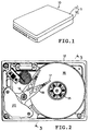
- Fig. 1 illustrates a hard disk drive unit (HDD) 10 as an example of a recording disk apparatus.
- the HDD 10 comprises a housing 11 formed by a combination of a box-shaped housing body 12 and a cover 13 for closing an opening defined in the housing body 12.
- the HDD 10 may be assembled into a computer housing, for example, or be used as an exterior storage device independent of the computer housing.
- the housing 10 serves to accommodate a magnetic disk 16 surrounding a rotation axis 15, and a magnetic head 17 opposed to a disk face of the magnetic disk 16.
- the magnetic head 17 is attached on the tip end of a carriage arm 19 which is capable of swinging about a swinging axis 18.
- an actuator 20 comprising a magnetic circuit driver the carriage arm 19 for swinging movement so as to position the magnetic head 17 at a target recording track on the disk face of the magnetic disk 16.
- a spindle motor 22 is magnetically connected to the rotation axis 15.
- a stationary axis 23 of the spindle motor 22 is fixed to the housing 11.
- Screws 24 serve to fix the base end of the stationary axis 23 on the bottom wall of the housing body 12.
- the tip end of the stationary axis 23 is coupled to the cover 13 by a screw 25.
- the rotation axis 15 is connected to the stationary axis 23 via ball bearings 26 for relative rotation therebetween.
- An outward flange 27 is formed on the base end of the rotation axis 15 so as to receive the magnetic disks 16 and spacer rings 28 which are superposed alternately. Employment of the spacer rings 28 serves to arrange the magnetic disks 16 at equal intervals in the axial direction.
- a clamp 31 is fixed at the tip end of the rotation axis 15.
- the clamp 31 serves to urge the alternately superposed magnetic disks 16 and spacer rings 28 against the outward flange 27.
- a plurality of screws 32 are adapted to fix a plane body 33 of the clamp 31 at the tip end of the rotation axis 15.
- the screws 32 are arranged at equal intervals on an imaginary circle concentric to the rotation axis 15.
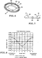
- Fig. 4 illustrates the clamp 31 according to a first embodiment of the present invention.
- the plane body 33 of the clamp 31 is provided with a plurality of screw bores 36 arranged along the imaginary circle 35.
- the respective screw bores 36 receive the corresponding screws 32.
- the clamp 31 is provided with a rigidity reduction mechanism 37 for reducing rigidity of the plane body 35 at the intermediate areas between the screw bore areas along the imaginary circle 35, relative to rigidity at the screw bore areas.
- the rigidity reduction mechanism 37 comprises an annular wall 38 raised from the surface of the plane body 33 at its periphery for reinforcing the rigidity of the plane body 33, and recesses 39 formed on the annular wall 38 at its top face in the intermediate areas.
- the recesses 39 serve to reduce the rigidity of the annular wall 38 at the intermediate areas in this rigidity reduction mechanism 37. Therefore, even if the tightening pressure form the screws 32 causes upward force at the intermediate areas, the upward force is absorbed by elasticity at the intermediate areas. As a result, deformation of the clamp 31 can be prevented so that undulation or deformation of the magnetic disk 16 in contact with the periphery of the clamp 31 can be avoided.
- the flying height W of the flying slider 17a for the magnetic head 17 is determined by the flying amount at the center of the flying slider 17a, as shown in Fig. 5. If undulation of the magnetic disk 16a can be avoided, less possibility remains in interference between the magnetic disk 16a and the head element 17b at the rear of the flying slider 17a. On the other hand, if the magnetic disk 16b suffers from undulation, enough flying height W of the flying slider 17a cannot reliably prevent the head element 17b from interfering with the magnetic disk 16b.
- the magnetic disk 16b is supposed to suffer from larger undulation at an inner area nearest to the clamp 31. Since the circumferential velocity tends to become slower at such inner area so that the flying height W of the flying slider 17a tends to get smaller, the probability of the interference is multiplied.
- the function of the rigidity reduction mechanism 37 serves to reduce the flying height W of the flying slider 17a without interference between the head element 17b and the magnetic disk 16a.
- the clamp 31 may be formed by pressing a sheet of aluminum or a stainless steel, by cold forging a bulk of Duralumin (trademark), or the like. It is preferable to select material for the clamp 31 in consideration of strength and rigidity in the formed clamp 31, and thermal expansion coefficient. For example, aluminum may be selected if the magnetic disk 16 employs an aluminum disk substrate, and a stainless steel may be selected if the magnetic disk 16 employs a glass disk substrate.
- tapered surfaces 40 may be formed in the recesses 39 to be continuous from the top surface of the annular wall 38 as shown in Fig. 6, for example.
- the tapered surfaces 40 are adapted to facilitate the forming of the recesses 39 by a press.
- curved surfaces 41 may be formed at connection between the bottom of the recess 39 and the tapered surfaces 40 and at connection between the top surface of the annular wall 38 and the tapered surfaces 40, as shown in Fig. 7.
- the curved surfaces 41 serve to prevent concentration of stress around the connection between the bottom of the recess 39 and the tapered surfaces 40 and the connection between the top surface of the annular wall 38 and the tapered surfaces 40. Accordingly, the tightening pressure may be maintained constant from the screws 32 for a longer term when the clamp 31 is fixed to the rotation axis 15.
- Fig. 8 illustrates undulation profiles for the aluminum magnetic disk 16 of 0.8mm thickness urged by the clamp 31.
- the vertical axis defines the amount of sink generated on the magnetic disk 16 by the tightening pressure from the screws 32.
- the amount of sink is measured from zero level which is defined by a level of the disk surface of the magnetic disk 16 without tightening pressure from the clamp 31.
- Undulation profile of the magnetic disk 16 is measured at periphery of the clamp 31.
- the horizontal axis defines the circumferential positions divided at equal intervals around the periphery of the clamp 31 on the magnetic disk 16.
- Fig. 9 illustrates a clamp 31a according to a second embodiment of the present invention.
- the rigidity reduction mechanism 37 comprises recesses 45 formed on the annular wall 38 at its side face or outer face at the intermediate areas.
- the recesses 45 serve to reduce the rigidity of the annular wall 38 at the intermediate areas in the same manner as the aforementioned first embodiment, so that the disk face of the magnetic disk 16 is kept flat.
- the identical reference numerals or characters are attached to the structure achieving the same effect or function as of the aforementioned first embodiment, and the detailed description thereof may be omitted.
- a balancer 46 may be attached to the clamp 31a, as shown in Fig. 10, for providing the rotating magnetic disk 16 with uniform centrifugal force so as to suppress vibration of the rotating magnetic disk 16.
- the balancer 46 may be formed by superposing a stainless steel layer 47 and an adhesive layer 48.
- An adhesive 49 serves to attach the balancer 46 to the inner surface of the annular wall 38.
- the annular wall 38 maintains a continuous inner surface irrespective of the recesses 45 so as to isolate the inner space of the annular wall 38 from the surrounding outer space, so that the balancer 46 which happens to fall off from the annular wall 38 cannot fall out of the clamp 31a toward the surrounding disk face of the magnetic disk 16.
- Fig. 11 illustrates a clamp 31b according to a third embodiment of the present invention.
- the rigidity reduction mechanism 37 comprises through holes 51 formed in the plane body 33 at the intermediate areas defined between the screw bore areas along the imaginary circle 35.
- One through hole 51 may be disposed in every intermediate area, or a plurality of through holes 51 may be disposed in every intermediate area as shown in Fig. 11.
- the clamp 31b serves to reduce the rigidity of the plane body 33 at the intermediate areas in the same manner as the aforementioned first and second embodiments, so that the disk face of the magnetic disk 16 is kept flat.
- the identical reference numerals or characters are attached to the structure achieving the same effect or function as of the aforementioned first and second embodiments, and the detailed description thereof may be omitted.
- through holes 51a, 51b of different diameters may be formed as shown in Fig. 12. More specifically, the large through hole 51a is formed in the middle of a pair of the screw bores 36, and the small through holes 51b having the diameter smaller than that of the large through hole 51a are disposed in areas between the large through hole 51a and the screw bores 35.
- the through holes 51a, 51b serve to vary the rigidity of the plane body 33 in the circumferential direction, so that it is possible to precisely adjust the deformation of the plane body 33.
- Fig. 13 illustrates a clamp 31c according to a fourth embodiment of the present invention.
- an annular wall 55 is formed to rise from the periphery of the plane body 33.
- the wall thickness D of the annular wall 55 is larger than that of the plane body 33 as shown in Fig. 14.
- the rigidity of the plane body 33 is reinforced at the periphery of the plane body in contact with the magnetic disk 16, while the rigidity is relatively reduced in area around the screw bores 36.
- the clamp 31c may be formed by grinding a bulk of metallic material.
- the identical reference numerals or characters are attached to the structure achieving the same effect or function as of the aforementioned first embodiment, and the detailed description thereof may be omitted.
Landscapes
- Holding Or Fastening Of Disk On Rotational Shaft (AREA)
- Rotational Drive Of Disk (AREA)
Applications Claiming Priority (2)
| Application Number | Priority Date | Filing Date | Title |
|---|---|---|---|
| JP13506298 | 1998-05-18 | ||
| JP13506298A JP4027499B2 (ja) | 1998-05-18 | 1998-05-18 | 記録ディスク装置および押し付けクランプ |
Publications (3)
| Publication Number | Publication Date |
|---|---|
| EP0959466A2 true EP0959466A2 (fr) | 1999-11-24 |
| EP0959466A3 EP0959466A3 (fr) | 2000-07-19 |
| EP0959466B1 EP0959466B1 (fr) | 2005-05-18 |
Family
ID=15143002
Family Applications (1)
| Application Number | Title | Priority Date | Filing Date |
|---|---|---|---|
| EP98123293A Expired - Lifetime EP0959466B1 (fr) | 1998-05-18 | 1998-12-08 | Appareil d'enregistrement de disques et disposittif de serrage pour cet appareil |
Country Status (6)
| Country | Link |
|---|---|
| US (1) | US6504674B2 (fr) |
| EP (1) | EP0959466B1 (fr) |
| JP (1) | JP4027499B2 (fr) |
| KR (1) | KR19990087009A (fr) |
| CN (1) | CN1170282C (fr) |
| DE (1) | DE69830233T2 (fr) |
Families Citing this family (17)
| Publication number | Priority date | Publication date | Assignee | Title |
|---|---|---|---|---|
| JP3727209B2 (ja) * | 1999-12-09 | 2005-12-14 | 富士通株式会社 | 磁気ディスク装置 |
| KR20030021678A (ko) * | 2001-09-07 | 2003-03-15 | 삼성전자주식회사 | 하드 디스크 드라이브의 클램프 구조체 |
| US6822826B2 (en) * | 2001-12-13 | 2004-11-23 | Seagate Technology Llc | Disc fixing apparatus and associated method fixing a disc and motor in balanced rotation |
| US6850389B2 (en) | 2002-08-15 | 2005-02-01 | Seagate Technology Llc | Crowned disc clamp |
| US6754042B1 (en) * | 2002-10-31 | 2004-06-22 | Western Digital Technologies, Inc. | Disk drive comprising a notched disk clamp for improved disk balance |
| JP3959334B2 (ja) * | 2002-10-31 | 2007-08-15 | シナノケンシ株式会社 | 光ディスク装置のディスクチャッキング装置及び光ディスク装置 |
| US6885118B2 (en) * | 2003-08-28 | 2005-04-26 | Hitachi Global Storage Technologies Netherlands B.V. | Balance clip for reducing friction during clip adjustment in spindle motor and hard disk drive balance process |
| US7164554B2 (en) * | 2004-06-30 | 2007-01-16 | Hitachi Global Storage Technologies Netherlands Bv | Disk drive with hub and apparatus for prevention of lubrication migration for lubricated clamp fasteners in disk drive applications |
| AU302986S (en) * | 2004-09-14 | 2005-08-31 | Sony Computer Entertainment Inc | Arithmetic and control unit |
| AU302987S (en) * | 2004-09-14 | 2005-08-31 | Sony Computer Entertainment Inc | Arithmetic and control unit |
| US7684152B2 (en) | 2004-09-24 | 2010-03-23 | Wd Media, Inc. | Method of mitigating eccentricity in a disk drive with DTR media |
| US7529064B1 (en) | 2005-11-21 | 2009-05-05 | Western Digital Technologies, Inc. | Disk drive including a balancing element with first and second cavities and a cylindrical portion disposed about a spindle motor hub |
| JP2007265542A (ja) * | 2006-03-29 | 2007-10-11 | Fujitsu Ltd | クランプリング及びそれを有するディスク装置 |
| US20070263321A1 (en) * | 2006-05-09 | 2007-11-15 | Chan Andre S | System and method for integrated spindle balance and contamination control for disk drives |
| US7729082B2 (en) * | 2006-07-25 | 2010-06-01 | Hitachi Global Storage Technologies Netherlands B.V. | Application of PFPES for HDD screw lubricant |
| USD604601S1 (en) * | 2008-04-25 | 2009-11-24 | Ann Helen Hystad | Vibration clamp for a ring seal |
| US8824099B2 (en) * | 2012-04-12 | 2014-09-02 | Intri-Plex Technologies, Inc. | Disk clamp having uniform clamping load and index mark |
Family Cites Families (23)
| Publication number | Priority date | Publication date | Assignee | Title |
|---|---|---|---|---|
| US4205357A (en) * | 1978-06-15 | 1980-05-27 | Pertec Computer Corporation | Disk drive unit incorporating a field-replaceable fixed disk assembly |
| US4317146A (en) * | 1979-12-03 | 1982-02-23 | Micropolis Corporation | Compact magnetic disk storage system |
| US4561035A (en) * | 1982-07-21 | 1985-12-24 | Sperry Corporation | Method and apparatus for clamping and balancing rotatable members |
| JPS62121955A (ja) * | 1985-11-21 | 1987-06-03 | Seiko Epson Corp | 磁気デイスク装置 |
| US4864443A (en) * | 1987-11-02 | 1989-09-05 | Seagate Technology, Inc. | Disc clamping device |
| GB2230891B (en) * | 1988-07-18 | 1992-04-08 | Seagate Technology | Disc clamp |
| US5274517A (en) * | 1988-07-18 | 1993-12-28 | Seagate Technology, Inc. | Disk clamp with annular spring section |
| US5031061A (en) * | 1989-09-27 | 1991-07-09 | Quantum Corporation | Disk drive hub assembly |
| CA2021357A1 (fr) * | 1989-11-13 | 1991-05-14 | Neil R. Pyke | Support flexible pour pile de disques |
| JPH0547129A (ja) * | 1991-08-14 | 1993-02-26 | Hitachi Ltd | 回転デイスク装置 |
| US5295030A (en) * | 1992-06-05 | 1994-03-15 | Seagate Technology, Inc. | Low profile disc clamp |
| US5572382A (en) * | 1993-04-07 | 1996-11-05 | Kabushiki Kaisha Toshiba | Magnetic disk drive having balanced magnetic disk mounted on rotor of motor |
| US5490024A (en) * | 1993-11-08 | 1996-02-06 | Conner Peripherals, Inc. | Disk clamp having an annular section of increased rigidity |
| US5486961A (en) * | 1994-08-30 | 1996-01-23 | International Business Machines Corporation | Resilient compliant clamp for data storage disk drives |
| US5528434A (en) * | 1995-03-10 | 1996-06-18 | Seagate Technology, Inc. | Disc clamp with integrated stiffener for hard disc drives |
| JP2606683B2 (ja) | 1995-04-26 | 1997-05-07 | 日本電気株式会社 | 磁気ディスク装置 |
| KR970007074A (ko) | 1995-07-26 | 1997-02-21 | 배순훈 | 가스오븐레인지의 가스누설감지장치 |
| JP2856700B2 (ja) * | 1995-09-27 | 1999-02-10 | インターナショナル・ビジネス・マシーンズ・コーポレイション | デイスク装置 |
| JPH09223346A (ja) | 1996-02-16 | 1997-08-26 | Toshiba Corp | データ記録装置 |
| JPH09320160A (ja) | 1996-05-31 | 1997-12-12 | Nhk Spring Co Ltd | ディスク体のクランプ構造 |
| JPH1083601A (ja) | 1996-09-06 | 1998-03-31 | Matsushita Electric Ind Co Ltd | 磁気ディスク駆動用モータのハブ及びその製造方法 |
| US5790345A (en) * | 1996-11-15 | 1998-08-04 | Integral Peripherals, Inc. | Disk clamp with tabs shaped to apply equal forces at equally spaced locations around an axis of rotation of a disk drive |
| US5912784A (en) * | 1996-11-19 | 1999-06-15 | Seagate Technology, Inc. | Dual member disc clamp for uniform clamping load distribution |
-
1998
- 1998-05-18 JP JP13506298A patent/JP4027499B2/ja not_active Expired - Fee Related
- 1998-12-08 EP EP98123293A patent/EP0959466B1/fr not_active Expired - Lifetime
- 1998-12-08 DE DE69830233T patent/DE69830233T2/de not_active Expired - Fee Related
- 1998-12-09 US US09/208,049 patent/US6504674B2/en not_active Expired - Fee Related
- 1998-12-11 KR KR1019980054461A patent/KR19990087009A/ko not_active Ceased
-
1999
- 1999-01-27 CN CNB991012739A patent/CN1170282C/zh not_active Expired - Fee Related
Also Published As
| Publication number | Publication date |
|---|---|
| DE69830233D1 (de) | 2005-06-23 |
| EP0959466A3 (fr) | 2000-07-19 |
| US6504674B2 (en) | 2003-01-07 |
| JP4027499B2 (ja) | 2007-12-26 |
| CN1170282C (zh) | 2004-10-06 |
| CN1236168A (zh) | 1999-11-24 |
| KR19990087009A (ko) | 1999-12-15 |
| US20010043431A1 (en) | 2001-11-22 |
| DE69830233T2 (de) | 2005-10-13 |
| EP0959466B1 (fr) | 2005-05-18 |
| JPH11328834A (ja) | 1999-11-30 |
Similar Documents
| Publication | Publication Date | Title |
|---|---|---|
| US6504674B2 (en) | Recording disk apparatus and clamp therefor | |
| US5801901A (en) | Disc drive clamp fastener including a clamp disc indentation | |
| US20090207528A1 (en) | Disc flutter compensating suspension | |
| US5490022A (en) | Data storage apparatus and disk fixing method for preventing the deformation of disks by regulating where the storage apparatus is fixed to the disk | |
| US5751519A (en) | Bearing unit, carriage assembly with the bearing unit, and magnetic disk apparatus | |
| JP3727209B2 (ja) | 磁気ディスク装置 | |
| US6788495B2 (en) | Disc pack assembly | |
| US5754372A (en) | Actuator bearing cartridge for top down assembly | |
| US6078475A (en) | Low friction pivot for rotary actuator in disk drive | |
| US6888699B2 (en) | Disc drive clamp having centering features | |
| EP1560212B1 (fr) | Dispositif de maintien de disque et entraînement de disque dur comprenant un tel dispositif | |
| KR100370763B1 (ko) | 하드디스크 드라이브의 스웨이지 마운트 플레이트 | |
| US5729406A (en) | Lightweight actuator in a computer mass memory storage device | |
| JP2006112505A (ja) | 軸受機構、キャリッジアセンブリ及び磁気ディスク装置 | |
| EP1383122B1 (fr) | Dispositif de serrage de disque pour appareil à disque | |
| US7545601B2 (en) | Magnetic disk drive with line contact | |
| JP4108696B2 (ja) | ディスク装置および押し付けクランプ | |
| US20060103975A1 (en) | Disk driving apparatus and magnetic disk apparatus having the same | |
| JP2001331995A (ja) | 磁気ディスク装置 | |
| JPH07262748A (ja) | 記憶装置の記録媒体取付構造 | |
| US7701664B2 (en) | Mounting spindle shaft in magnetic disk drive | |
| KR100408512B1 (ko) | 디스크 조립체 | |
| US20060119988A1 (en) | Head stack assembly incorporating a pivot assembly having solid lubrication | |
| JP2005233271A (ja) | 転がり軸受装置 | |
| JPH10275410A (ja) | スピンドルモータおよびこれを備えた磁気ディスク装置 |
Legal Events
| Date | Code | Title | Description |
|---|---|---|---|
| PUAI | Public reference made under article 153(3) epc to a published international application that has entered the european phase |
Free format text: ORIGINAL CODE: 0009012 |
|
| AK | Designated contracting states |
Kind code of ref document: A2 Designated state(s): DE GB |
|
| AX | Request for extension of the european patent |
Free format text: AL;LT;LV;MK;RO;SI |
|
| PUAL | Search report despatched |
Free format text: ORIGINAL CODE: 0009013 |
|
| AK | Designated contracting states |
Kind code of ref document: A3 Designated state(s): AT BE CH CY DE DK ES FI FR GB GR IE IT LI LU MC NL PT SE |
|
| AX | Request for extension of the european patent |
Free format text: AL;LT;LV;MK;RO;SI |
|
| AKX | Designation fees paid | ||
| 17P | Request for examination filed |
Effective date: 20010116 |
|
| RBV | Designated contracting states (corrected) |
Designated state(s): DE GB |
|
| 17Q | First examination report despatched |
Effective date: 20030918 |
|
| GRAP | Despatch of communication of intention to grant a patent |
Free format text: ORIGINAL CODE: EPIDOSNIGR1 |
|
| GRAS | Grant fee paid |
Free format text: ORIGINAL CODE: EPIDOSNIGR3 |
|
| GRAA | (expected) grant |
Free format text: ORIGINAL CODE: 0009210 |
|
| AK | Designated contracting states |
Kind code of ref document: B1 Designated state(s): DE GB |
|
| REG | Reference to a national code |
Ref country code: GB Ref legal event code: FG4D |
|
| REF | Corresponds to: |
Ref document number: 69830233 Country of ref document: DE Date of ref document: 20050623 Kind code of ref document: P |
|
| PLBE | No opposition filed within time limit |
Free format text: ORIGINAL CODE: 0009261 |
|
| STAA | Information on the status of an ep patent application or granted ep patent |
Free format text: STATUS: NO OPPOSITION FILED WITHIN TIME LIMIT |
|
| 26N | No opposition filed |
Effective date: 20060221 |
|
| PGFP | Annual fee paid to national office [announced via postgrant information from national office to epo] |
Ref country code: DE Payment date: 20081205 Year of fee payment: 11 |
|
| PGFP | Annual fee paid to national office [announced via postgrant information from national office to epo] |
Ref country code: GB Payment date: 20081203 Year of fee payment: 11 |
|
| REG | Reference to a national code |
Ref country code: GB Ref legal event code: 732E Free format text: REGISTERED BETWEEN 20091112 AND 20091118 |
|
| GBPC | Gb: european patent ceased through non-payment of renewal fee |
Effective date: 20091208 |
|
| PG25 | Lapsed in a contracting state [announced via postgrant information from national office to epo] |
Ref country code: DE Free format text: LAPSE BECAUSE OF NON-PAYMENT OF DUE FEES Effective date: 20100701 |
|
| PG25 | Lapsed in a contracting state [announced via postgrant information from national office to epo] |
Ref country code: GB Free format text: LAPSE BECAUSE OF NON-PAYMENT OF DUE FEES Effective date: 20091208 |