EP0958999B2 - Flügelprofil - Google Patents
Flügelprofil Download PDFInfo
- Publication number
- EP0958999B2 EP0958999B2 EP99303952A EP99303952A EP0958999B2 EP 0958999 B2 EP0958999 B2 EP 0958999B2 EP 99303952 A EP99303952 A EP 99303952A EP 99303952 A EP99303952 A EP 99303952A EP 0958999 B2 EP0958999 B2 EP 0958999B2
- Authority
- EP
- European Patent Office
- Prior art keywords
- panels
- aerofoil
- tip
- attached
- leading edge
- Prior art date
- Legal status (The legal status is an assumption and is not a legal conclusion. Google has not performed a legal analysis and makes no representation as to the accuracy of the status listed.)
- Expired - Lifetime
Links
Images


Classifications
-
- B—PERFORMING OPERATIONS; TRANSPORTING
- B64—AIRCRAFT; AVIATION; COSMONAUTICS
- B64C—AEROPLANES; HELICOPTERS
- B64C3/00—Wings
- B64C3/38—Adjustment of complete wings or parts thereof
- B64C3/44—Varying camber
- B64C3/48—Varying camber by relatively-movable parts of wing structures
Definitions
- This invention related to an aerofoil and, more particularly but not exclusively to an aerofoil for an aircraft.
- US Patent Specification 5,222,699 describes an aircraft trailing edge control surface having a variable contour transition region at least one end thereof whereby there is a smooth transition between the control surface when deflected relative to the wing and the wing trailing edge region itself.
- the control surface may also be flexible chordwise throughout its length. In order for this chordwise flexibility to be achieved. the upper skin of the control surface is arranged to slide under the surface of the main body of the wing.
- US Patent Specification 4,429,844 describes an aircraft wing tip having variable camber to conform to a variable camber leading edge to the wing.
- the wing tip variable camber is achieved via scissor plates to which are attached elastomeric skins, the scissor plates being anchored to corresponding points in the leading edge control surfaces.
- Priort art document WO/96/40553 discloses elastomeric transition regions reinforced by flexible rods sliding within elastomeric panels.
- edges of aircraft aerofoils such as the leading edge of a wing
- shape of the edges of aircraft aerofoils may be adjusted in use to enhance the operation of the aircraft.
- present adjustable leading edge designs expose slots that limit the performance of the wing. These slots result in pressure losses that limit the lift resulting from the aerofoil.
- an aerofoil according to the subject matter of claim 1.
- Fig. 1 is a schematic diagram of a leading edge 10 according to the invention.
- the leading edge 10 has a rotary actuator 12 for pivoting the leading edge 10.
- a linear actuator 14 is used for blunting the leading edge.
- the dashed lines 16 show the leading edge in an extended state.
- the leading edge is typically connected to the body 18 of the wing of an aircraft.
- Fig. 2 is a schematic diagram of the leading edge 10 of Fig. 1 in a deflected and blunted state.
- a reinforced elastomer panel is used to realize the gapless smooth curvilinear shape of the leading edge throughout its operating range, as will be discussed in more detail below.
- Fig. 3 is a cross sectional view of an embodiment of a leading edge 20 according to the invention.
- a hard durometer elastomer tip 22 has a first edge 24 and a second edge 26.
- the first edge 24 of the hard durometer elastomer tip 22 is connected to a first edge 27 of a first reinforced elastomer panel 28.
- a plurality of reinforcing members are attached to the hard durometer elastomer tip 22. These reinforcing members slide within the first reinforced elastomer panel 28.
- the reinforced elastomer panel will be discussed in more detail in conjunction with Fig. 6.
- a second edge 30 of the fist reinforced elastomer panel 28 is connected to a first rigid block 32.
- the first rigid block 32 is made of a metal.
- the first rigid block 32 is attached to the body of the wing of the aircraft.
- the second edge 26 of the hard durometer elastomer tip 22 is connected to a first edge 34 of a second elastomer panel 36.
- a second edge 38 of the second elastomer panel 36 is connected to a second rigid block 40.
- the leading edge includes a rotary actuator 42 and a blunting actuator 44.
- the rotary actuator 42 deflects the leading edge up or down and the blunting actuator 44 pushes the tip 22 in and out.
- Fig. 4 is a top view of the leading edge of Fig. 3. This view shows the tip 22 connected to the reinforced elastomer panel 28 and the rigid block 32.
- a transition section connects to the body of the wing.
- the transition section is included at an inner edge of the leading edge in one embodiment.
- the invention provides for a leading edge that does not have any gaps and provides a wide range of shape tailoring for the leading edge.
- Fig. 5 is a cross sectional view of an embodiment of a leading edge 50 according to the invention.
- the leading edge 50 has a hard durometer elastomer tip 52.
- a reinforced elastomer panel 54 connects to the tip 52.
- a second reinforced elastomer panel 56 connects to the other side of the tip 52.
- Both reinforced elastomer panels 54, 56, which form working surfaces of the aerofoil, have a rigid block 58, 60 that attaches to the body 62 of the wing of the aircraft.
- a skeletal structure 64 is attached to the body of the wing of the aircraft.
- the skeletal structure includes a base 66 connected to a rotor 68 by a rotary actuator 70.
- a blunting actuator 71 has a piston 72 that moves the tip 52 from a blunt state (retracted position) to an extended state (extended position).
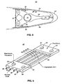
- Fig 6. is a perspective view of a rod reinforced elastomer panel 80.
- the elastomer panel 80 has a rod block 82 attached along one edge to an elastomer skin 84.
- the elastomer skin 84 is capable of stretching to 100% of its unstressed length.
- the elastomer skin 84 is capable of twisting.
- a plurality of flexible reinforced rods 86 are attached to the rod block 82 and are allowed to slide freely inside the elastomer skin 84.
- the leading edge of the rods 86 are attached to the hard durometer tip.
- the rods 86 are made from quartz, epoxy or composites and flex without breaking. The stiffness of these reinforcements is designed to yield a specific extended shape.
- the rods 86 slide freely inside a second rod block 88.
- the rods 86 provide the elastomer skin 84 with a smooth curvilinear shape when the elastomer panel 80 is elongated, deflected or twisted. This curvilinear shape provides a good aerodynamic shape without any discontinuities that cause turbulence and drag.
- a plurality of attachment provisions 90 are used to attach the elastomer panel 80 to the body of the wing of the aircraft.
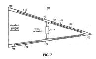
- Fig. 7 is a cross sectional view of an embodiment of an anti-icing edge 100 for the trailing edge of a wing of an aircraft.
- a hard durometer elastomer tip 102 is connected to a first reinforced elastomer panel 104.
- a reinforcing member 106 is shown inside the elastomer.
- a second reinforced elastomer panel 108 is connected to the other side of the hard durometer tip 102.
- a pair of center rigid blocks 110 are connected to the elastomer panels 104, 108.
- An actuator (anti-icing) 111 is shown connected between the pair of center rigid blocks 110.
- a third reinforced elastomer 112 and a fourth reinforced elastomer panel 114 are connected to the pair of center rigid blocks 110.
- a pair of inner rigid blocks 116, 118 attach to the body of the wing of the aircraft.
- the actuator 111 By moving the actuator 111 the reinforced elastomer panels 104, 108, 112 114 are forced to deflect. Any ice attached to the structure 100 is cracked and popped off the edge.
- leading edge that allows a wide range of shape tailoring without exposing gaps.
- de-icing edge has been described.
- the leading edge and de-icing edges are combined into a single edge.
- the hard durometer elastomer tip 22 is preferably made of an elasomeric material having a shore A hardness of from 32 or below to 55 or above. SilasticTM J (shore A hardness 55) and ELTM 78 (Shore A hardness 32) both appear satisfactory.
- the elastomeric material in the rod reinforced elastomer panels 28, 80 may comprise silicone and the reinforcing rods themselves can comprise a quartz epoxy.
Landscapes
- Engineering & Computer Science (AREA)
- Mechanical Engineering (AREA)
- Aviation & Aerospace Engineering (AREA)
- Structures Of Non-Positive Displacement Pumps (AREA)
- Tires In General (AREA)
- Footwear And Its Accessory, Manufacturing Method And Apparatuses (AREA)
- Actuator (AREA)
Claims (6)
- Tragfläche (18), mit einem Körper und einer Vorderkante, die eine Spitze (22, 52) aufweist, oberen und unteren elastomeren Platten (28, 36, 54, 56), die Arbeitsoberflächen bilden und jeweils mehrere Verstärkungselemente (86) enthalten, und Aktuatormitteln (12, 42, 70), die so beschaffen sind, dass sie die Vorderkante schwenken und die Platten biegen, wobei die Spitze (22, 52) aus einem harten Durometer-Elastomer gebildet ist und eine obere und eine untere Kante (24, 26) für die Befestigung an der oberen bzw. der unteren Platte definiert, wobei die Aktuatormittel an der Spitze befestigt sind, wobei die Verstärkungselemente (86) in den Platten (28, 36, 54, 56) frei gleiten können; die Platten (54, 56, 108) an ihren äußeren Enden an der Spitze (22, 58) befestigt sind; und die Platten (28, 36, 54, 56) an ihren inneren Enden in starren Blöcken (32, 40, 58, 60) kulminieren, die an der Tragfläche (18) befestigt sind; wobei die Tragfläche, die Platten und die Spitzen ohne Unterbrechung ineinander übergehen.
- Tragfläche nach Anspruch 1, mit einem Stumpfmachungsaktuator (14, 44, 71, 72), der die Kante ausfährt und verkürzt.
- Tragfläche nach Anspruch 2, mit einer Skelettstruktur (68), die an dem Körper angelenkt ist und den Stumpfmachungsaktuator unterstützt.
- Tragfläche nach einem der Ansprüche 1 bis 3, bei der die Betätigungsmittel zum Biegen der Platten ein Drehaktuator (12, 42, 70) sind.
- Tragfläche nach einem der vorhergehenden Ansprüche, bei der die Verstärkungselemente (86) an der Spitze (22, 52) starr befestigt sind und in den starren Blöcken (58, 60) gleiten.
- Tragfläche nach einem der vorhergehenden Ansprüche, die eine Hinterkante mit einer harten Durometer-Elastomer-Spitze (102) besitzt, wobei die obere Oberfläche der Hinterkante in gegenseitiger Verbindung nacheinander einen starren Block (116), eine verstärkte elastomere Platte (112), einen starren Block (110) und eine verstärkte elastomere Platte (104) umfasst, wobei die untere Oberfläche der Hinterkante in gegenseitiger Verbindung nacheinander einen starren Block (118), eine verstärkte elastomere Platte (114), einen starren Block (110) und eine verstärkte elastomere Platte (108) umfasst, wobei die Blöcke (116, 118) außerdem am Körper des Flügels befestigt sind und die Platten (104, 108) außerdem an der harten Durometer-Spitze (102) befestigt sind und wobei ein Aktuator (111) vorhanden ist, der zwischen dem oberen und dem unteren Block (110) wirkt, um Eis von der oberen und von der unteren Oberfläche zu lösen.
Applications Claiming Priority (2)
| Application Number | Priority Date | Filing Date | Title |
|---|---|---|---|
| US8282798A | 1998-05-21 | 1998-05-21 | |
| US82827 | 1998-05-21 |
Publications (4)
| Publication Number | Publication Date |
|---|---|
| EP0958999A2 EP0958999A2 (de) | 1999-11-24 |
| EP0958999A3 EP0958999A3 (de) | 2001-08-29 |
| EP0958999B1 EP0958999B1 (de) | 2004-04-14 |
| EP0958999B2 true EP0958999B2 (de) | 2007-08-29 |
Family
ID=22173712
Family Applications (1)
| Application Number | Title | Priority Date | Filing Date |
|---|---|---|---|
| EP99303952A Expired - Lifetime EP0958999B2 (de) | 1998-05-21 | 1999-05-21 | Flügelprofil |
Country Status (3)
| Country | Link |
|---|---|
| US (1) | US6213433B1 (de) |
| EP (1) | EP0958999B2 (de) |
| DE (1) | DE69916360T3 (de) |
Families Citing this family (44)
| Publication number | Priority date | Publication date | Assignee | Title |
|---|---|---|---|---|
| USRE44313E1 (en) | 1996-10-22 | 2013-06-25 | The Boeing Company | Airplane with unswept slotted cruise wing airfoil |
| TW491340U (en) * | 2000-04-11 | 2002-06-11 | Yuan Mei Decorative Lamp & Amp | Water-proof lamp socket of decorative lamp string |
| US6588709B1 (en) | 2002-03-20 | 2003-07-08 | The Boeing Company | Apparatus for variation of a wall skin |
| US7258308B2 (en) * | 2002-07-02 | 2007-08-21 | The Boeing Company | Method and apparatus for controlling airflow with a gapped trailing edge device having a flexible flow surface |
| US6877695B2 (en) * | 2002-12-13 | 2005-04-12 | The Boeing Company | Hinge cover integration into door seal edges |
| AU2004225883B2 (en) * | 2003-03-31 | 2010-06-17 | Technical University Of Denmark | Control of power, loads and/or stability of a horizontal axis wind turbine by use of variable blade geometry control |
| US7059563B2 (en) * | 2003-06-03 | 2006-06-13 | The Boeing Company | Systems, apparatuses, and methods for moving aircraft control surfaces |
| GB0326228D0 (en) * | 2003-11-10 | 2003-12-17 | Airbus Uk Ltd | Wing tip device |
| US6799739B1 (en) | 2003-11-24 | 2004-10-05 | The Boeing Company | Aircraft control surface drive system and associated methods |
| US7424350B2 (en) * | 2004-02-02 | 2008-09-09 | The Boeing Company | Vehicle control systems and corresponding sizing methods |
| US7229049B2 (en) * | 2004-05-04 | 2007-06-12 | Lockheed Martin Corporation | Unitized rotary actuator hinge fitting |
| US6978971B1 (en) * | 2004-06-15 | 2005-12-27 | The Boeing Company | Methods and apparatuses for controlling airflow proximate to engine/airfoil systems |
| US7270305B2 (en) * | 2004-06-15 | 2007-09-18 | The Boeing Company | Aircraft leading edge apparatuses and corresponding methods |
| US7494094B2 (en) * | 2004-09-08 | 2009-02-24 | The Boeing Company | Aircraft wing systems for providing differential motion to deployable lift devices |
| US7264206B2 (en) * | 2004-09-30 | 2007-09-04 | The Boeing Company | Leading edge flap apparatuses and associated methods |
| US7322547B2 (en) * | 2005-01-31 | 2008-01-29 | The Boeing Company | Aerospace vehicle leading edge slat devices and corresponding methods |
| US7338018B2 (en) * | 2005-02-04 | 2008-03-04 | The Boeing Company | Systems and methods for controlling aircraft flaps and spoilers |
| US7204454B2 (en) * | 2005-02-25 | 2007-04-17 | Northrop Grumman Corporation | Aircraft with articulated leading edge of fuselage and wings |
| US7246770B2 (en) * | 2005-02-25 | 2007-07-24 | Northrop Grumman Corporation | Aircraft with rotatable leading edge of fuselage and wings |
| US7216835B2 (en) * | 2005-02-25 | 2007-05-15 | Northrop Grumman Corporation | Aircraft with extendable leading edge of fuselage and wings |
| DE102005014884B3 (de) | 2005-04-01 | 2006-09-14 | Nordex Energy Gmbh | Rotorblatt für eine Windenergieanlage |
| US7309043B2 (en) * | 2005-04-27 | 2007-12-18 | The Boeing Company | Actuation device positioning systems and associated methods, including aircraft spoiler droop systems |
| US7721999B2 (en) * | 2005-05-20 | 2010-05-25 | The Boeing Company | Aerospace vehicle fairing systems and associated methods |
| US7300021B2 (en) * | 2005-05-20 | 2007-11-27 | The Boeing Company | Aerospace vehicle fairing systems and associated methods |
| US7367530B2 (en) * | 2005-06-21 | 2008-05-06 | The Boeing Company | Aerospace vehicle yaw generating systems and associated methods |
| US7500641B2 (en) * | 2005-08-10 | 2009-03-10 | The Boeing Company | Aerospace vehicle flow body systems and associated methods |
| US7708231B2 (en) | 2005-11-21 | 2010-05-04 | The Boeing Company | Aircraft trailing edge devices, including devices having forwardly positioned hinge lines, and associated methods |
| US7475854B2 (en) | 2005-11-21 | 2009-01-13 | The Boeing Company | Aircraft trailing edge devices, including devices with non-parallel motion paths, and associated methods |
| FR2898865B1 (fr) | 2006-03-27 | 2008-05-30 | Cetim Cermat Ass Loi De 1901 | Profil aerodynamique ou hydrodynamique pouvant etre deforme de maniere continue et controlee |
| EP2021243B1 (de) * | 2006-04-27 | 2018-10-24 | Flexsys, Inc. | Anpassungsfähiges strukturkonzept für veränderliche oberflächenkonturen |
| US7578484B2 (en) * | 2006-06-14 | 2009-08-25 | The Boeing Company | Link mechanisms for gapped rigid krueger flaps, and associated systems and methods |
| FR2911113B1 (fr) * | 2007-01-04 | 2009-09-11 | Airbus France Sa | Empennage horizontal pour aeronef. |
| US9039372B2 (en) * | 2007-04-30 | 2015-05-26 | Vestas Wind Systems A/S | Wind turbine blade |
| WO2008131800A1 (en) * | 2007-04-30 | 2008-11-06 | Vestas Wind Systems A/S | A wind turbine blade |
| US7954769B2 (en) * | 2007-12-10 | 2011-06-07 | The Boeing Company | Deployable aerodynamic devices with reduced actuator loads, and related systems and methods |
| US7766282B2 (en) | 2007-12-11 | 2010-08-03 | The Boeing Company | Trailing edge device catchers and associated systems and methods |
| US8382045B2 (en) | 2009-07-21 | 2013-02-26 | The Boeing Company | Shape-changing control surface |
| GB2473448A (en) * | 2009-09-09 | 2011-03-16 | Vestas Wind Sys As | Wind Turbine Rotor Blade With Undulating Flap Hinge Panel |
| GB201018924D0 (en) * | 2010-11-09 | 2010-12-22 | Airbus Operations Ltd | Seal |
| US9174723B2 (en) | 2013-04-03 | 2015-11-03 | The Boeing Company | Shape memory alloy rods for actuation of continuous surfaces |
| US9581145B2 (en) | 2013-05-14 | 2017-02-28 | The Boeing Company | Shape memory alloy actuation system for variable area fan nozzle |
| US9598167B2 (en) * | 2014-03-04 | 2017-03-21 | The Boeing Company | Morphing airfoil leading edge |
| US20170323239A1 (en) | 2016-05-06 | 2017-11-09 | General Electric Company | Constrained time computing control system to simulate and optimize aircraft operations with dynamic thermodynamic state and asset utilization attainment |
| DE102021005965B3 (de) | 2021-12-01 | 2022-11-10 | Friedrich Grimm | Rotorblatt für eine wind - oder wasserturbine sowie für ein drehflügelfahrzeug und insbesondere für einen hubschrauber |
Citations (3)
| Publication number | Priority date | Publication date | Assignee | Title |
|---|---|---|---|---|
| US3716209A (en) † | 1970-06-01 | 1973-02-13 | Mini Of Technology | Fluid dynamic lift generating or control force generating structures |
| WO1996040553A1 (en) † | 1995-06-07 | 1996-12-19 | Northrop Grumman Corporation | Elastomeric transition for aircraft control surface |
| US5681014A (en) † | 1992-05-15 | 1997-10-28 | Palmer; Harry W. | Torsional twist airfoil control means |
Family Cites Families (26)
| Publication number | Priority date | Publication date | Assignee | Title |
|---|---|---|---|---|
| US2368702A (en) | 1943-04-08 | 1945-02-06 | Raymond D Bourne | Streamlined hinge line for aircraft |
| US2539576A (en) * | 1945-08-28 | 1951-01-30 | Bendix Aviat Corp | Inflatable ice eliminating apparatus |
| US2731221A (en) | 1952-06-25 | 1956-01-17 | North American Aviation Inc | Aircraft door installation |
| US2932470A (en) | 1955-05-24 | 1960-04-12 | Chance Vought Aircraft Inc | Variable contour airfoil |
| US2970794A (en) | 1957-05-24 | 1961-02-07 | Herbert C Johnson | Inflatable de-icing boot |
| US3109613A (en) | 1960-11-28 | 1963-11-05 | Mabel Wilson Raspet | Variable-camber airfoil |
| US3698668A (en) | 1971-04-08 | 1972-10-17 | Boeing Co | Variable camber airfoil |
| US4012013A (en) | 1976-02-05 | 1977-03-15 | The Boeing Company | Variable camber inlet for supersonic aircraft |
| GB1536331A (en) | 1976-04-01 | 1978-12-20 | Secr Defence | Aerofoils |
| US4341176A (en) | 1980-09-29 | 1982-07-27 | Orrison William W | Air foil with reversible camber |
| US4429844A (en) * | 1982-09-29 | 1984-02-07 | The Boeing Company | Variable camber aircraft wing tip |
| US4892626A (en) | 1988-01-21 | 1990-01-09 | Boeing Company | Method for plating one side of a woven fabric sheet |
| US5222699A (en) * | 1990-04-16 | 1993-06-29 | Ltv Aerospace And Defense Company | Variable control aircraft control surface |
| KR960702399A (ko) | 1993-05-06 | 1996-04-27 | 제임스, 씨. 존슨 | 구조형상 제어장치 및 제어방법(apparatus and method for controlling the shape of structures) |
| US5662294A (en) | 1994-02-28 | 1997-09-02 | Lockheed Martin Corporation | Adaptive control surface using antagonistic shape memory alloy tendons |
| US5975463A (en) | 1995-12-21 | 1999-11-02 | Mcdonnell Douglas | Expandable aircraft bay and method |
| US5810291A (en) | 1996-03-19 | 1998-09-22 | Geiger; Michael Watson | Continuous moldline technology system |
| US6048581A (en) | 1996-09-24 | 2000-04-11 | Mcdonnell Douglas Corporation | Elastic ground plane and method |
| US5947422A (en) | 1997-04-29 | 1999-09-07 | Mcdonnell Douglas | Tail for an aircraft |
| US5941480A (en) | 1997-05-08 | 1999-08-24 | Mcdonnell Douglas | Hinge line skin system for an aircraft |
| US5896191A (en) | 1997-05-13 | 1999-04-20 | Mcdonnell Douglas | Reinforced elastomer panel with embedded strain and pressure sensors |
| US5927651A (en) | 1997-05-15 | 1999-07-27 | Mcdonnell Douglas | Expandable fuel cell |
| US5931422A (en) * | 1997-06-09 | 1999-08-03 | Mcdonnell Douglas | Active reinforced elastomer system |
| US5913494A (en) | 1997-07-25 | 1999-06-22 | Mcdonnell Douglas | Blade seal for an aircraft |
| US5947417A (en) | 1997-07-25 | 1999-09-07 | Mcdonnell Douglas | Fairing for an expandable bay |
| US5975466A (en) | 1998-06-02 | 1999-11-02 | Northrop Grumman Corporation | Variable displacement fuel tank for aircraft |
-
1999
- 1999-05-21 EP EP99303952A patent/EP0958999B2/de not_active Expired - Lifetime
- 1999-05-21 DE DE69916360T patent/DE69916360T3/de not_active Expired - Lifetime
-
2000
- 2000-03-14 US US09/525,535 patent/US6213433B1/en not_active Expired - Lifetime
Patent Citations (3)
| Publication number | Priority date | Publication date | Assignee | Title |
|---|---|---|---|---|
| US3716209A (en) † | 1970-06-01 | 1973-02-13 | Mini Of Technology | Fluid dynamic lift generating or control force generating structures |
| US5681014A (en) † | 1992-05-15 | 1997-10-28 | Palmer; Harry W. | Torsional twist airfoil control means |
| WO1996040553A1 (en) † | 1995-06-07 | 1996-12-19 | Northrop Grumman Corporation | Elastomeric transition for aircraft control surface |
Also Published As
| Publication number | Publication date |
|---|---|
| US6213433B1 (en) | 2001-04-10 |
| EP0958999A3 (de) | 2001-08-29 |
| DE69916360T3 (de) | 2008-06-05 |
| DE69916360D1 (de) | 2004-05-19 |
| EP0958999B1 (de) | 2004-04-14 |
| DE69916360T2 (de) | 2004-08-12 |
| EP0958999A2 (de) | 1999-11-24 |
Similar Documents
| Publication | Publication Date | Title |
|---|---|---|
| EP0958999B2 (de) | Flügelprofil | |
| US4429844A (en) | Variable camber aircraft wing tip | |
| US5794893A (en) | Elastomeric transition for aircraft control surface | |
| US6349903B2 (en) | Control surface for an aircraft | |
| EP1398269B2 (de) | Verfahren und Vorrichtung zur Strömungsbeeinflussung mittels einer Flügelvorderkante mit flexibler Oberfläche | |
| EP2604509B1 (de) | Tragflügelhinterkantespitze mit verstellbarer Krümmung | |
| US6173924B1 (en) | Low density flexible edge transition | |
| US5222699A (en) | Variable control aircraft control surface | |
| US6152405A (en) | Lift body having a variable camber | |
| US4200253A (en) | Aircraft wing drooping leading edge device | |
| US6164599A (en) | Aerofoil profile with variable profile adaptation | |
| US4053124A (en) | Variable camber airfoil | |
| EP1207101A3 (de) | Flügelvorderkante mit veränderbarer Wölbung für Flügelprofile | |
| KR102069783B1 (ko) | 트레일링 에지 플랩을 갖는 헬리콥터 에어로포일 | |
| KR102055015B1 (ko) | 액티브 거니 플랩 | |
| US20090001223A1 (en) | Flexible Control Surface for an Aircraft | |
| CN108454826A (zh) | 用于飞行器的柔性密封件 | |
| US4718619A (en) | Manoeuverable supercritical wing section | |
| US4093156A (en) | Supersonic transport | |
| JPH08216997A (ja) | ヘリコプタのロータブレード | |
| EP0120007B1 (de) | Variable wölbung einer flugzeugflügelspitze | |
| EP1695904B1 (de) | Fluggerät mit gelenkig verbundener Vorderkante des Rumpfes und der Tragflügel | |
| EP0189973A1 (de) | Aufblasbarer Enteiser | |
| GB2161775A (en) | Rollable airfoil and aircraft using same | |
| IL142411A (en) | Movable surface on an aircraft |
Legal Events
| Date | Code | Title | Description |
|---|---|---|---|
| PUAI | Public reference made under article 153(3) epc to a published international application that has entered the european phase |
Free format text: ORIGINAL CODE: 0009012 |
|
| AK | Designated contracting states |
Kind code of ref document: A2 Designated state(s): AT BE CH CY DE DK ES FI FR GB GR IE IT LI LU MC NL PT SE |
|
| AX | Request for extension of the european patent |
Free format text: AL;LT;LV;MK;RO;SI |
|
| RAP1 | Party data changed (applicant data changed or rights of an application transferred) |
Owner name: MCDONNELL DOUGLAS CORPORATION |
|
| PUAL | Search report despatched |
Free format text: ORIGINAL CODE: 0009013 |
|
| AK | Designated contracting states |
Kind code of ref document: A3 Designated state(s): AT BE CH CY DE DK ES FI FR GB GR IE IT LI LU MC NL PT SE |
|
| AX | Request for extension of the european patent |
Free format text: AL;LT;LV;MK;RO;SI |
|
| 17P | Request for examination filed |
Effective date: 20020124 |
|
| AKX | Designation fees paid |
Free format text: DE FR GB SE |
|
| 17Q | First examination report despatched |
Effective date: 20021119 |
|
| GRAP | Despatch of communication of intention to grant a patent |
Free format text: ORIGINAL CODE: EPIDOSNIGR1 |
|
| GRAS | Grant fee paid |
Free format text: ORIGINAL CODE: EPIDOSNIGR3 |
|
| GRAA | (expected) grant |
Free format text: ORIGINAL CODE: 0009210 |
|
| AK | Designated contracting states |
Kind code of ref document: B1 Designated state(s): DE FR GB SE |
|
| REG | Reference to a national code |
Ref country code: GB Ref legal event code: FG4D |
|
| REF | Corresponds to: |
Ref document number: 69916360 Country of ref document: DE Date of ref document: 20040519 Kind code of ref document: P |
|
| PG25 | Lapsed in a contracting state [announced via postgrant information from national office to epo] |
Ref country code: SE Free format text: LAPSE BECAUSE OF FAILURE TO SUBMIT A TRANSLATION OF THE DESCRIPTION OR TO PAY THE FEE WITHIN THE PRESCRIBED TIME-LIMIT Effective date: 20040714 |
|
| ET | Fr: translation filed | ||
| PLBQ | Unpublished change to opponent data |
Free format text: ORIGINAL CODE: EPIDOS OPPO |
|
| PLBI | Opposition filed |
Free format text: ORIGINAL CODE: 0009260 |
|
| PLAX | Notice of opposition and request to file observation + time limit sent |
Free format text: ORIGINAL CODE: EPIDOSNOBS2 |
|
| 26 | Opposition filed |
Opponent name: AIRBUS SAS Effective date: 20050114 |
|
| PLAX | Notice of opposition and request to file observation + time limit sent |
Free format text: ORIGINAL CODE: EPIDOSNOBS2 |
|
| PLBB | Reply of patent proprietor to notice(s) of opposition received |
Free format text: ORIGINAL CODE: EPIDOSNOBS3 |
|
| PUAH | Patent maintained in amended form |
Free format text: ORIGINAL CODE: 0009272 |
|
| STAA | Information on the status of an ep patent application or granted ep patent |
Free format text: STATUS: PATENT MAINTAINED AS AMENDED |
|
| 27A | Patent maintained in amended form |
Effective date: 20070829 |
|
| AK | Designated contracting states |
Kind code of ref document: B2 Designated state(s): DE FR GB SE |
|
| ET3 | Fr: translation filed ** decision concerning opposition | ||
| REG | Reference to a national code |
Ref country code: FR Ref legal event code: PLFP Year of fee payment: 17 |
|
| REG | Reference to a national code |
Ref country code: FR Ref legal event code: PLFP Year of fee payment: 18 |
|
| REG | Reference to a national code |
Ref country code: FR Ref legal event code: PLFP Year of fee payment: 19 |
|
| REG | Reference to a national code |
Ref country code: FR Ref legal event code: PLFP Year of fee payment: 20 |
|
| PGFP | Annual fee paid to national office [announced via postgrant information from national office to epo] |
Ref country code: DE Payment date: 20180529 Year of fee payment: 20 |
|
| PGFP | Annual fee paid to national office [announced via postgrant information from national office to epo] |
Ref country code: FR Payment date: 20180525 Year of fee payment: 20 |
|
| PGFP | Annual fee paid to national office [announced via postgrant information from national office to epo] |
Ref country code: GB Payment date: 20180529 Year of fee payment: 20 |
|
| REG | Reference to a national code |
Ref country code: DE Ref legal event code: R071 Ref document number: 69916360 Country of ref document: DE |
|
| REG | Reference to a national code |
Ref country code: GB Ref legal event code: PE20 Expiry date: 20190520 |
|
| PG25 | Lapsed in a contracting state [announced via postgrant information from national office to epo] |
Ref country code: GB Free format text: LAPSE BECAUSE OF EXPIRATION OF PROTECTION Effective date: 20190520 |