EP0958213B1 - Trommel für die herstellung absorbierender artikel - Google Patents
Trommel für die herstellung absorbierender artikel Download PDFInfo
- Publication number
- EP0958213B1 EP0958213B1 EP97929638A EP97929638A EP0958213B1 EP 0958213 B1 EP0958213 B1 EP 0958213B1 EP 97929638 A EP97929638 A EP 97929638A EP 97929638 A EP97929638 A EP 97929638A EP 0958213 B1 EP0958213 B1 EP 0958213B1
- Authority
- EP
- European Patent Office
- Prior art keywords
- drum
- engagement means
- application drum
- application
- cam
- Prior art date
- Legal status (The legal status is an assumption and is not a legal conclusion. Google has not performed a legal analysis and makes no representation as to the accuracy of the status listed.)
- Expired - Lifetime
Links
Images

Classifications
-
- B—PERFORMING OPERATIONS; TRANSPORTING
- B65—CONVEYING; PACKING; STORING; HANDLING THIN OR FILAMENTARY MATERIAL
- B65H—HANDLING THIN OR FILAMENTARY MATERIAL, e.g. SHEETS, WEBS, CABLES
- B65H39/00—Associating, collating, or gathering articles or webs
- B65H39/14—Associating sheets with webs
-
- A—HUMAN NECESSITIES
- A61—MEDICAL OR VETERINARY SCIENCE; HYGIENE
- A61F—FILTERS IMPLANTABLE INTO BLOOD VESSELS; PROSTHESES; DEVICES PROVIDING PATENCY TO, OR PREVENTING COLLAPSING OF, TUBULAR STRUCTURES OF THE BODY, e.g. STENTS; ORTHOPAEDIC, NURSING OR CONTRACEPTIVE DEVICES; FOMENTATION; TREATMENT OR PROTECTION OF EYES OR EARS; BANDAGES, DRESSINGS OR ABSORBENT PADS; FIRST-AID KITS
- A61F13/00—Bandages or dressings; Absorbent pads
- A61F13/15—Absorbent pads, e.g. sanitary towels, swabs or tampons for external or internal application to the body; Supporting or fastening means therefor; Tampon applicators
- A61F13/15577—Apparatus or processes for manufacturing
- A61F13/15666—Wrapping formed fibrous webs or pads, e.g. the pads being formed by uniting pad pieces cut from fibrous webs
-
- A—HUMAN NECESSITIES
- A61—MEDICAL OR VETERINARY SCIENCE; HYGIENE
- A61F—FILTERS IMPLANTABLE INTO BLOOD VESSELS; PROSTHESES; DEVICES PROVIDING PATENCY TO, OR PREVENTING COLLAPSING OF, TUBULAR STRUCTURES OF THE BODY, e.g. STENTS; ORTHOPAEDIC, NURSING OR CONTRACEPTIVE DEVICES; FOMENTATION; TREATMENT OR PROTECTION OF EYES OR EARS; BANDAGES, DRESSINGS OR ABSORBENT PADS; FIRST-AID KITS
- A61F13/00—Bandages or dressings; Absorbent pads
- A61F13/15—Absorbent pads, e.g. sanitary towels, swabs or tampons for external or internal application to the body; Supporting or fastening means therefor; Tampon applicators
- A61F13/15577—Apparatus or processes for manufacturing
- A61F13/15764—Transferring, feeding or handling devices; Drives
-
- B—PERFORMING OPERATIONS; TRANSPORTING
- B65—CONVEYING; PACKING; STORING; HANDLING THIN OR FILAMENTARY MATERIAL
- B65H—HANDLING THIN OR FILAMENTARY MATERIAL, e.g. SHEETS, WEBS, CABLES
- B65H2406/00—Means using fluid
- B65H2406/30—Suction means
- B65H2406/34—Suction grippers
- B65H2406/345—Rotary suction grippers
- B65H2406/3452—Rotary suction grippers performing reciprocating movement during rotation
- B65H2406/34525—Rotary suction grippers performing reciprocating movement during rotation parallely to the axis of rotation
Definitions
- the invention relates to a device as defined in the first part of claim 1.
- Drums or lay-down drums as they are often called, are known in the prior art.
- the drums are used in production of absorbent products such as nappies, incontinence articles and the like.
- the drums are provided with material engagement means which receive a piece of material from a supply means and then apply it to an underlying sheet of an absorbent product positioned on a moving conveyor belt.
- the receiving location and the delivery location are typically 180° opposed and the drum rotates continuously so as to pass through the receiving location and then the delivery location.
- the piece of material may be of any type, but is typically a pre-formed piece, such as an absorbent core or other absorbent layer.
- the engagement means is generally arranged so that an under-pressure (e.g. a vacuum) is applied to the material engagement means on the drum when the article is in the collecting position. The under-pressure is applied through perforations in the engagement means.
- an under-pressure e.g. a vacuum
- the under-pressure is maintained on the material engagement means as the drum rotates, until the drum has rotated so that the material piece attached thereto is in contact with the conveyor belt, or the part-formed absorbent article thereon.
- An over-pressure is then applied to the engagement means so as to secure release of the material piece from the application drum.
- the absorbent articles being formed are typically placed head-to-toe across the conveyor belt (i.e. one article is rotated 180° with respect to the next). If, as is normal, a material piece must be laid onto the part-formed articles at a location which is not in line with, or to one side of, the centre-line of the drum, then two laterally-spaced application drums (or a similar arrangement) are often used. In such a case, each of the drums delivers a material piece to alternate ones of the part-formed products.
- the present invention has the object of overcoming the aforementioned problems by providing an improved application drum.
- the essential features of the drum are defined in claim 1, whilst preferred features of the drum are defined in the dependent claims.
- a single drum is provided which can be used for applying material pieces at varying transverse locations on a longitudinally-travelling conveyor belt.
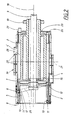
- Fig. 1 shows an application drum, generally denoted as 1, positioned above a conveyor belt 22 having a centre-line 16.
- the conveyor belt is driven in a direction "X" shown by the arrow upstream of the drum.
- the application drum 1 rotates about its longitudinal axis of rotation 18 shown in chain-dotted lines.
- the axis 18 will most commonly be a shaft, supported for rotation on a support 17.
- absorbent articles 23, 24 On the conveyor belt 22, a plurality of absorbent articles 23, 24 being formed are indicated in phantom lines.
- the absorbent articles are normally asymmetric and are placed in a head-to-toe relationship as shown.
- the absorbent articles 23, 24 may be connected to one another to form a connected web of absorbent articles which are later separated.
- the drum has four material engagement means 4, 4' thereon, only two of which are visible in Fig. 1. Said engagement means are positioned at 90° intervals around the surface. It is possible however to use only one material engagement means if desired, although the manufacturing operation will be slower. In the embodiment shown however, the material engagement means 4, 4' are arranged as two opposed pairs, each of said engagement means in one pair being offset by 180° with respect to the other.
- Each engagement means is arranged for reciprocal movement in a direction Y with respect to the drum 1.
- material engagement means 4 at the uppermost position on the drum 1 is in a collection position.
- a material piece 3 is supplied thereto from a supply device (not shown) such as a conveyor belt or a supply wheel.
- the centre of the collection position is substantially in line with the axis 16 of the conveyor belt.
- the central axis 21 (see Fig. 2) of the drum is preferably in line with axis 16 of the conveyor belt.
- the material engagement means 4 rotates therewith.
- the material engagement means 4 is displaced to the right (looking from the view point in Fig. 1) by an arrangement which will be described below.
- the material piece 3 When it reaches its lowermost position (i.e. 180° displaced to its shown position), the material piece 3 will have moved far enough to the right so that it will be in a correct position to be applied on the article 24, at a location which is more to one side of the axis 16 of the conveyor belt. The material piece 3 is then removed from the means 4 and applied to the article 24.
- the material engagement means 4 will be reciprocated back to its substantially central location on the drum 1, for picking up a subsequent material piece.
- the material engagement means 4' undergoes similar movements as the drum rotates. However, instead of being moved to the right of the axis 16 (or centre-line 21) as engagement means 4, it is moved in the opposite direction, allowing it to be placed in the correct location on the articles 23 which are displaced towards the left side of the conveyor belt 22.
- the articles 23, 24, may be centrally located with reference to the axis 16, but the material pieces 3 are often required to be placed in a non-symmetric position on said articles.
- the engagement means are formed with perforations 20, through which air over-pressures or air under-pressures may be applied to the surface of means 4.
- an under-pressure is applied in the collection position (i.e. the uppermost position) and is maintained in a material holding zone until the delivery or deposition zone (lower position) is reached.
- zone "C" where no material piece 3 is attached to the engagement means, a gradually increasing under-pressure may be applied or no pressure at all. However, an over-pressure may be applied to allow any small remaining fragments of the material piece 3 to be expelled before a new material piece 3 is received. If expulsion is used, e.g. by means of an over-pressure, a suitable collection device (not shown) for collecting the remaining small fragments should preferably be arranged.
- Each of the material engagement means 4, 4' is positioned on a separate respective carriage member 2 in the form of a plate.
- the carriage member is guided for reciprocal movement with respect to the drum by means of guide sections inserted onto the drum as modular units.
- Each guide section has a flat support surface 7 and shallow guiding walls 14 which slidingly engage with the outer walls of the plate. In this way a reciprocal movement, strictly parallel to the drum axis 18 can be ensured. Exact parallel movement is not however an absolute pre-requisite since small variations will not substantially effect the performance of the final absorbent product.
- a guide element 6 in the form of a connection means is provided between the carriage members 2 (the plates) and a control means, in the form of a cam, placed inside the drum 1.
- the guide element 6 is in the form of a pin which is attached (e.g. by having a threaded end thereon for a lock nut) at its outer end to the carriage member 2.
- the pin is provided with a member having a cam engagement surface. The pin passes through a slot 5 provided in the support surface 7.
- the inner end is provided with a cam engagement surface in the form of a cam follower 11' such as a cam roller which is adapted to fit into a continuous cam curve 12 provided on a fixed cylindrical drum 8 (see Fig. 2).
- a cam follower 11' such as a cam roller which is adapted to fit into a continuous cam curve 12 provided on a fixed cylindrical drum 8 (see Fig. 2).
- Fig. 2 which is a view through line II-II in Fig. 1, and not merely a simple vertical section through drum 8, the cam curve 12 as depicted at its uppermost point in Fig. 2 corresponds to a position of about 90° before the top position shown in Fig. 1. At the top position shown in Fig. 1 however, the cam curve starts at a location which is close to the middle of the drum 8 surface. The cam curve is arranged such that the cam follower 11' will then be displaced to the right, or to the left, from this generally central location, depending on which engagement means, 4 or 4', is concerned. An example of part of a cam curve is shown as 25 in dotted lines.
- cam curves 12, 13 are provided, one for each of the pairs of carriage members (plates) 2 and respective means 4', 4 and rollers 11', 11.
- the two different cam curves 12, 13 allow the plates to move in different directions (to the left or to the right in a direction Y) from the material piece collection position which is uppermost in Fig. 1.
- a drive device (not shown) is connected to a drive element 10, such as a gear wheel, in order to rotate the application drum 1 and the carriage members 2 connected thereto.
- the cam drum 8 is however maintained in a fixed position and one end of the drum 1 is supported on a bearing 15, for example, for rotation with respect to the fixed drum shaft 9 running therethrough.
- the cam drum may be releasably lockable to allow it to be rotated and then relocked before operation commences.
- a pressure supply device 27 and a pressure control plate 26 (which is fixed in space) are provided.
- the pressure control plate 26 has a hole 29 therein for passage of the drum 1 drive shaft.
- the pressure control plate 26 is slidingly engaged against the rear end (the right-hand end in figure 2) of the drum 1.
- Air pressure (under-pressure or over-pressure) is supplied to the perforations 20, which are preferably present substantially all the way along zone 19, by means of airways 28 between the plates 2 and the drum 1.
- the particular configuration of the control plate 26 allows air pressure to be correctly applied at the desired locations during rotation of the drum 1. Further details of the pressure plate are not indicated here as this is not part of the present invention and not required for understanding the principles of the present invention.
- Cam curves 12, 13 on a cam drum have been shown in Fig. 2 as examples of cam control members.
- Such an arrangement has the particular advantage of being simple and reliable, with a minimum of moving elements.
- more complicated systems could be used such as those comprising hydraulically or pneumatically actuated members used to displace the guide elements 6, or even the carriage members 2 directly.
Claims (10)
- Applikationstrommel (1) zur Verwendung bei der Herstellung von Absorptionsartikeln (23), wobei die Applikationstrommel eine Längs-Drehachse (18) aufweist, und wobei die Trommel (1) Material-Eingriffseinrichtungen (4) an der Außenseite derselben sowohl zum Aufnehmen als auch Zuführen einer Materialkomponente (3) aufweist,
dadurch gekennzeichnet, dass
die Material-Eingriffseinrichtung (4) für eine hin- und hergehende Bewegung bezüglich der Trommel (1) angeordnet ist, wobei die Bewegung in einer Richtung (Y) vorliegt, die im Wesentlichen parallel zu der Drehachse (18) der Trommel (1) ist. - Applikationstrommel (1) nach Anspruch 1,
dadurch gekennzeichnet, dass
die Material-Eingriffseinrichtung (4) an ein Schlittenelement (2) angebracht ist, und dadurch, dass die Trommel (1) mit Führungselementen (14) zum Führen des Schlittenelements (2) versehen ist. - Applikationstrommel nach Anspruch 2,
dadurch gekennzeichnet, dass
das Schlittenelement (2) ein plattenartiges Element ist. - Applikationstrommel nach einem der vorangehenden Ansprüche,
dadurch gekennzeichnet, dass
die Material-Eingriffseinrichtung (4) ein Führungselement (6, 11) aufweist, das daran angebracht ist, wobei das Führungselement (6, 11) durch einen Schlitz (5) in der Applikationstrommel (1) tritt. - Applikationstrommel nach Anspruch 4,
dadurch gekennzeichnet, dass
das Führungselement (6, 11) einen Nockenstößel (11; 11') auf weist, wobei der Nockenstößel in einer fortlaufenden Nockenkurve (12) geführt ist, die innerhalb der Applikationstrommel (1) angeordnet ist. - Applikationstrommel nach Anspruch 5,
dadurch gekennzeichnet, dass
die Nockenkurve (12) in der Oberfläche eines im Wesentlichen festen zylindrischen Trommelelements (8) vorgesehen ist. - Applikationstrommel nach Anspruch 5 oder 6,
dadurch gekennzeichnet, dass
mehrere Material-Eingriffseinrichtungen (4, 4') vorliegen, die jeweils mit einem jeweiligen Nockenstößel (11, 11') verbunden sind, und dadurch, dass zwei getrennte Nockenkurven (12, 13) vorhanden sind, wobei innerhalb einer jeweiligen der Kurven (12, 13) der jeweilige Nockenstößel (11, 11') in Eingriff ist. - Applikationstrommel nach einem der vorangehenden Ansprüche,
dadurch gekennzeichnet, dass
die Material-Eingriffseinrichtung (4, 4') zwischen einer Aufnahmeposition, die nahe der Mittellinie (21) der Applikationstrommel (1) angeordnet ist, und einer Zuführposition hin- und hergeht, die von der Mittellinie der Applikationstrommel (1) beabstandet angeordnet ist. - Applikationstrommel nach Anspruch 8,
dadurch gekennzeichnet, dass
mehrere Eingriffseinrichtungen (4 und 4') um den Umfang der Trommel (1) vorgesehen sind, wobei aufeinanderfolgende der Einrichtungseinrichtungen (4, 4') derart angeordnet sind, dass sie in entgegengesetzten Richtungen bezüglich ihrer Aufnahmeposition an der Trommel (1) versetzt werden. - Applikationstrommel nach einem der vorangehenden Ansprüche,
dadurch gekennzeichnet, dass
die Aufnahme und Zuführung der Materialkomponente (3) unter Verwendung von Einrichtungen (27) stattfindet, die einen Unterdruck bzw. einen Überdruck zuführen, wobei die Drücke durch eine Oberfläche (19) der Material-Eingriffseinrichtung (4, 4') aufgebracht werden, die mit Perforationen (20) versehen ist.
Applications Claiming Priority (3)
| Application Number | Priority Date | Filing Date | Title |
|---|---|---|---|
| SE9602565A SE507136C2 (sv) | 1996-06-28 | 1996-06-28 | Appliceringstrumma för användning vid produktion av absorberande artiklar |
| SE9602565 | 1996-06-28 | ||
| PCT/SE1997/000951 WO1998000356A1 (en) | 1996-06-28 | 1997-06-02 | Application drum for use in the production of absorbent articles |
Publications (2)
| Publication Number | Publication Date |
|---|---|
| EP0958213A1 EP0958213A1 (de) | 1999-11-24 |
| EP0958213B1 true EP0958213B1 (de) | 2002-01-16 |
Family
ID=20403203
Family Applications (1)
| Application Number | Title | Priority Date | Filing Date |
|---|---|---|---|
| EP97929638A Expired - Lifetime EP0958213B1 (de) | 1996-06-28 | 1997-06-02 | Trommel für die herstellung absorbierender artikel |
Country Status (6)
| Country | Link |
|---|---|
| US (1) | US6170636B1 (de) |
| EP (1) | EP0958213B1 (de) |
| JP (1) | JP2000514024A (de) |
| DE (1) | DE69709686T2 (de) |
| SE (1) | SE507136C2 (de) |
| WO (1) | WO1998000356A1 (de) |
Families Citing this family (25)
| Publication number | Priority date | Publication date | Assignee | Title |
|---|---|---|---|---|
| AU2774699A (en) * | 1999-02-19 | 2000-09-04 | Procter & Gamble Company, The | Apparatus for manufacturing hygienic articles having a horizontal circular drum |
| US6491153B1 (en) * | 1999-11-24 | 2002-12-10 | Heidelberger Druckmaschinen Ag | Device and method for splitting a printed product stream |
| JP3798298B2 (ja) | 2000-12-01 | 2006-07-19 | 株式会社瑞光 | 回転装置、着用物品の搬送方法およびウェブの搬送方法 |
| US6604623B2 (en) | 2001-01-31 | 2003-08-12 | Zuiko Corporation | Article transfer apparatus |
| US7008497B2 (en) | 2002-08-22 | 2006-03-07 | Zuiko Corporation | Method and apparatus for producing wearing article |
| JP4536547B2 (ja) * | 2005-02-22 | 2010-09-01 | 株式会社瑞光 | 着用物品の製造方法および製造装置 |
| US7398870B2 (en) * | 2005-10-05 | 2008-07-15 | Curt G. Joa, Inc | Article transfer and placement apparatus |
| DE102006046624A1 (de) * | 2006-09-29 | 2008-04-03 | Brötje-Automation GmbH | Verfahren und Transportvorrichtung zum Transportieren von Gegenständen |
| ITBO20070431A1 (it) | 2007-06-19 | 2008-12-20 | Gdm Spa | Macchina e metodo per la realizzazione di articoli assorbenti. |
| IT1390737B1 (it) * | 2008-07-04 | 2011-09-23 | Gdm Spa | Macchina per la realizzazione di articoli assorbenti. |
| DE102008063786A1 (de) * | 2008-12-18 | 2010-07-01 | Romaco Pharmatechnik Gmbh | Vorrichtung zum Vereinzeln von Teilen |
| US8100253B2 (en) | 2009-06-30 | 2012-01-24 | The Procter & Gamble Company | Methods and apparatuses for transferring discrete articles between carriers |
| GB2476965B (en) | 2010-01-15 | 2014-12-10 | Intelligent Energy Ltd | Transfer mechanism |
| US20120157279A1 (en) * | 2010-12-20 | 2012-06-21 | Uwe Schneider | Process and Apparatus for Joining Flexible Components |
| DE102012001831B4 (de) * | 2012-02-01 | 2015-03-19 | Hochland Se | Verfahren und Vorrichtung zum Trennen und Stapeln von Lebensmittelscheiben |
| US8607959B2 (en) | 2012-04-16 | 2013-12-17 | The Procter & Gamble Company | Rotational assemblies and methods for transferring discrete articles |
| US8833542B2 (en) | 2012-04-16 | 2014-09-16 | The Procter & Gamble Company | Fluid systems and methods for transferring discrete articles |
| US8820513B2 (en) | 2012-04-16 | 2014-09-02 | The Procter & Gamble Company | Methods for transferring discrete articles |
| US8720666B2 (en) | 2012-04-16 | 2014-05-13 | The Procter & Gamble Company | Apparatuses for transferring discrete articles |
| JP6092406B2 (ja) | 2012-10-23 | 2017-03-08 | ザ プロクター アンド ギャンブル カンパニー | ウェブ上に別個の物品を取着する方法 |
| US9463942B2 (en) | 2013-09-24 | 2016-10-11 | The Procter & Gamble Company | Apparatus for positioning an advancing web |
| US9511952B1 (en) | 2015-06-23 | 2016-12-06 | The Procter & Gamble Company | Methods for transferring discrete articles |
| US9511951B1 (en) | 2015-06-23 | 2016-12-06 | The Procter & Gamble Company | Methods for transferring discrete articles |
| JP2022002893A (ja) | 2020-06-23 | 2022-01-11 | ザ・ボーイング・カンパニーThe Boeing Company | プライバイプライ式製造プロセスにおいてラミネートプライの被トリミング部分を選択的に除去するための自動除去装置、システム、及び方法 |
| IT202100013556A1 (it) * | 2021-05-25 | 2022-11-25 | Azionaria Costruzioni Acma Spa | Metodo e dispositivo per compire operazioni su articoli trasportati lungo una linea manifatturiera |
Family Cites Families (8)
| Publication number | Priority date | Publication date | Assignee | Title |
|---|---|---|---|---|
| US2980231A (en) * | 1958-09-02 | 1961-04-18 | Albert F Goetze Inc | Automatic switching and storage conveyor |
| FR2121361B1 (de) * | 1971-01-06 | 1976-05-28 | Colgate Palmolive Co | |
| GB2074127B (en) * | 1980-03-04 | 1983-08-03 | Mardorf Peach & Co Ltd | Package handling |
| US4523671A (en) * | 1983-06-21 | 1985-06-18 | Paper Converting Machine Company | Apparatus for multiple lane stacking |
| CH667189A5 (de) | 1985-07-17 | 1988-09-30 | Oehler Ag | Vorrichtung zum setzen von dekorationselementen. |
| DE3836363A1 (de) * | 1988-10-26 | 1990-05-03 | Focke & Co | Verfahren und vorrichtung zum ueberfuehren von einbahnig zugefuehrten gegenstaenden auf mehrere abfoerderbahnen |
| US6022443A (en) | 1994-01-25 | 2000-02-08 | Kimberly-Clark Worldwide, Inc. | Method and apparatus for placing discrete parts onto a moving web |
| US6319347B1 (en) | 1994-01-25 | 2001-11-20 | Kimberly-Clark Worldwide, Inc. | Method for placing discrete parts transversely onto a moving web |
-
1996
- 1996-06-28 SE SE9602565A patent/SE507136C2/sv not_active IP Right Cessation
-
1997
- 1997-06-02 EP EP97929638A patent/EP0958213B1/de not_active Expired - Lifetime
- 1997-06-02 JP JP10504027A patent/JP2000514024A/ja active Pending
- 1997-06-02 US US09/194,970 patent/US6170636B1/en not_active Expired - Lifetime
- 1997-06-02 WO PCT/SE1997/000951 patent/WO1998000356A1/en active IP Right Grant
- 1997-06-02 DE DE69709686T patent/DE69709686T2/de not_active Expired - Lifetime
Also Published As
| Publication number | Publication date |
|---|---|
| DE69709686D1 (de) | 2002-02-21 |
| SE507136C2 (sv) | 1998-04-06 |
| SE9602565D0 (sv) | 1996-06-28 |
| EP0958213A1 (de) | 1999-11-24 |
| WO1998000356A1 (en) | 1998-01-08 |
| DE69709686T2 (de) | 2002-06-13 |
| SE9602565L (sv) | 1997-12-29 |
| JP2000514024A (ja) | 2000-10-24 |
| US6170636B1 (en) | 2001-01-09 |
Similar Documents
| Publication | Publication Date | Title |
|---|---|---|
| EP0958213B1 (de) | Trommel für die herstellung absorbierender artikel | |
| US9950439B2 (en) | Single transfer insert placement method and apparatus with cross-direction insert placement control | |
| US7975584B2 (en) | Single transfer insert placement method and apparatus | |
| US10266362B2 (en) | Single transfer insert placement method and apparatus | |
| EP1820757B1 (de) | Vorrichtung zur Übertragung und Platzierung von Artikeln mit aktivem Puck | |
| US7398870B2 (en) | Article transfer and placement apparatus | |
| EP1588862B1 (de) | Vorrichtung zum arbeitstaktgerechten Zuführen von Buchblocks, Büchern oder Druckprodukten zu einer Weiterverarbeitungsmaschine | |
| DE60220487T2 (de) | Vorrichtung zum Ausschneiden eines Artikels aus einem langen Band und zum Anhaften eines Artikels an einem Klebeband | |
| EP2659869B1 (de) | Vorrichtung für die Positionierung eines Einsatzes mit Einzelübertragung mit Querrichtungseinsatz-Positionierungssteuerung | |
| EP0687641B1 (de) | Verfahren und Vorrichtung zum Zuführen von Blättern | |
| JP2008143715A (ja) | シート材料の加工処理 | |
| DE3022525A1 (de) | Verfahren und vorrichtung zum automatischen aufbringen von aufklebern auf eine endlosbahn | |
| US4314868A (en) | Method and apparatus for preventing warp in corrugated cardboard | |
| EP3868694A1 (de) | Drehvorrichtung für eine fertigungsanlage für hygieneprodukte | |
| EP3773389A1 (de) | Vorrichtung zur formung von tampons | |
| US5775562A (en) | Conveying table with straightening device for continuously conveying a deformable material strip | |
| EP1314663B1 (de) | Staudrucklose Staurollenbahn | |
| DE10151484A1 (de) | Bogenanleger | |
| DE4332186C2 (de) | Verfahren und Vorrichtung zum Kaschieren von Flachmaterial-Zuschnitten | |
| US20120186944A1 (en) | Article transfer and placement apparatus with active puck | |
| US4572499A (en) | Process and apparatus for registering sheets | |
| WO2001034395A1 (de) | Präge-rotationsmaschine | |
| DE2654932C2 (de) | Vorrichtung zum Herstellen von Papierzylindern zum Züchten von Säumlingen | |
| DE10327647B4 (de) | Bodenlegevorrichtung | |
| EP3810533A1 (de) | Zuführung von unterdruck |
Legal Events
| Date | Code | Title | Description |
|---|---|---|---|
| PUAI | Public reference made under article 153(3) epc to a published international application that has entered the european phase |
Free format text: ORIGINAL CODE: 0009012 |
|
| 17P | Request for examination filed |
Effective date: 19981201 |
|
| AK | Designated contracting states |
Kind code of ref document: A1 Designated state(s): DE FR GB IT NL |
|
| GRAG | Despatch of communication of intention to grant |
Free format text: ORIGINAL CODE: EPIDOS AGRA |
|
| 17Q | First examination report despatched |
Effective date: 20010427 |
|
| GRAG | Despatch of communication of intention to grant |
Free format text: ORIGINAL CODE: EPIDOS AGRA |
|
| GRAH | Despatch of communication of intention to grant a patent |
Free format text: ORIGINAL CODE: EPIDOS IGRA |
|
| GRAH | Despatch of communication of intention to grant a patent |
Free format text: ORIGINAL CODE: EPIDOS IGRA |
|
| GRAA | (expected) grant |
Free format text: ORIGINAL CODE: 0009210 |
|
| REG | Reference to a national code |
Ref country code: GB Ref legal event code: IF02 |
|
| AK | Designated contracting states |
Kind code of ref document: B1 Designated state(s): DE FR GB IT NL |
|
| PG25 | Lapsed in a contracting state [announced via postgrant information from national office to epo] |
Ref country code: NL Free format text: LAPSE BECAUSE OF FAILURE TO SUBMIT A TRANSLATION OF THE DESCRIPTION OR TO PAY THE FEE WITHIN THE PRESCRIBED TIME-LIMIT Effective date: 20020116 |
|
| REF | Corresponds to: |
Ref document number: 69709686 Country of ref document: DE Date of ref document: 20020221 |
|
| PG25 | Lapsed in a contracting state [announced via postgrant information from national office to epo] |
Ref country code: GB Free format text: LAPSE BECAUSE OF NON-PAYMENT OF DUE FEES Effective date: 20020602 |
|
| ET | Fr: translation filed | ||
| NLV1 | Nl: lapsed or annulled due to failure to fulfill the requirements of art. 29p and 29m of the patents act | ||
| PLBE | No opposition filed within time limit |
Free format text: ORIGINAL CODE: 0009261 |
|
| STAA | Information on the status of an ep patent application or granted ep patent |
Free format text: STATUS: NO OPPOSITION FILED WITHIN TIME LIMIT |
|
| 26N | No opposition filed | ||
| GBPC | Gb: european patent ceased through non-payment of renewal fee |
Effective date: 20020602 |
|
| REG | Reference to a national code |
Ref country code: FR Ref legal event code: PLFP Year of fee payment: 20 |
|
| PGFP | Annual fee paid to national office [announced via postgrant information from national office to epo] |
Ref country code: DE Payment date: 20160524 Year of fee payment: 20 |
|
| PGFP | Annual fee paid to national office [announced via postgrant information from national office to epo] |
Ref country code: FR Payment date: 20160516 Year of fee payment: 20 |
|
| PGFP | Annual fee paid to national office [announced via postgrant information from national office to epo] |
Ref country code: IT Payment date: 20160621 Year of fee payment: 20 |
|
| REG | Reference to a national code |
Ref country code: DE Ref legal event code: R071 Ref document number: 69709686 Country of ref document: DE |