EP0957576A2 - Oberflächenwellenanordnung - Google Patents
Oberflächenwellenanordnung Download PDFInfo
- Publication number
- EP0957576A2 EP0957576A2 EP98117525A EP98117525A EP0957576A2 EP 0957576 A2 EP0957576 A2 EP 0957576A2 EP 98117525 A EP98117525 A EP 98117525A EP 98117525 A EP98117525 A EP 98117525A EP 0957576 A2 EP0957576 A2 EP 0957576A2
- Authority
- EP
- European Patent Office
- Prior art keywords
- idt
- electrode
- saw
- surface acoustic
- unidirectional
- Prior art date
- Legal status (The legal status is an assumption and is not a legal conclusion. Google has not performed a legal analysis and makes no representation as to the accuracy of the status listed.)
- Withdrawn
Links
Images


Classifications
-
- H—ELECTRICITY
- H03—ELECTRONIC CIRCUITRY
- H03H—IMPEDANCE NETWORKS, e.g. RESONANT CIRCUITS; RESONATORS
- H03H9/00—Networks comprising electromechanical or electro-acoustic devices; Electromechanical resonators
- H03H9/46—Filters
- H03H9/64—Filters using surface acoustic waves
-
- H—ELECTRICITY
- H03—ELECTRONIC CIRCUITRY
- H03H—IMPEDANCE NETWORKS, e.g. RESONANT CIRCUITS; RESONATORS
- H03H9/00—Networks comprising electromechanical or electro-acoustic devices; Electromechanical resonators
- H03H9/02—Details
- H03H9/125—Driving means, e.g. electrodes, coils
- H03H9/145—Driving means, e.g. electrodes, coils for networks using surface acoustic waves
- H03H9/14544—Transducers of particular shape or position
- H03H9/14552—Transducers of particular shape or position comprising split fingers
-
- H—ELECTRICITY
- H03—ELECTRONIC CIRCUITRY
- H03H—IMPEDANCE NETWORKS, e.g. RESONANT CIRCUITS; RESONATORS
- H03H9/00—Networks comprising electromechanical or electro-acoustic devices; Electromechanical resonators
- H03H9/46—Filters
- H03H9/64—Filters using surface acoustic waves
- H03H9/6423—Means for obtaining a particular transfer characteristic
- H03H9/6426—Combinations of the characteristics of different transducers
-
- H—ELECTRICITY
- H03—ELECTRONIC CIRCUITRY
- H03H—IMPEDANCE NETWORKS, e.g. RESONANT CIRCUITS; RESONATORS
- H03H9/00—Networks comprising electromechanical or electro-acoustic devices; Electromechanical resonators
- H03H9/02—Details
- H03H9/02535—Details of surface acoustic wave devices
- H03H9/02614—Treatment of substrates, e.g. curved, spherical, cylindrical substrates ensuring closed round-about circuits for the acoustical waves
- H03H9/02622—Treatment of substrates, e.g. curved, spherical, cylindrical substrates ensuring closed round-about circuits for the acoustical waves of the surface, including back surface
-
- H—ELECTRICITY
- H03—ELECTRONIC CIRCUITRY
- H03H—IMPEDANCE NETWORKS, e.g. RESONANT CIRCUITS; RESONATORS
- H03H9/00—Networks comprising electromechanical or electro-acoustic devices; Electromechanical resonators
- H03H9/02—Details
- H03H9/02535—Details of surface acoustic wave devices
- H03H9/02818—Means for compensation or elimination of undesirable effects
- H03H9/02866—Means for compensation or elimination of undesirable effects of bulk wave excitation and reflections
-
- H—ELECTRICITY
- H03—ELECTRONIC CIRCUITRY
- H03H—IMPEDANCE NETWORKS, e.g. RESONANT CIRCUITS; RESONATORS
- H03H9/00—Networks comprising electromechanical or electro-acoustic devices; Electromechanical resonators
- H03H9/02—Details
- H03H9/05—Holders; Supports
- H03H9/10—Mounting in enclosures
- H03H9/1064—Mounting in enclosures for surface acoustic wave [SAW] devices
- H03H9/1092—Mounting in enclosures for surface acoustic wave [SAW] devices the enclosure being defined by a cover cap mounted on an element forming part of the surface acoustic wave [SAW] device on the side of the IDT's
-
- H—ELECTRICITY
- H03—ELECTRONIC CIRCUITRY
- H03H—IMPEDANCE NETWORKS, e.g. RESONANT CIRCUITS; RESONATORS
- H03H9/00—Networks comprising electromechanical or electro-acoustic devices; Electromechanical resonators
- H03H9/02—Details
- H03H9/125—Driving means, e.g. electrodes, coils
Definitions
- the present invention relates to a surface acoustic wave device, particularly a surface acoustic wave device using a unidirectional interdigital transducer (referred to as IDT hereafter).
- IDT unidirectional interdigital transducer
- unidirectional IDTs which excite surface acoustic waves (referred to as SAW hereafter) only in one direction have been developed in order to reduce loss of IDTs which excite the SAW going forward in two directions.
- unidirectional IDTs unidirectional IDTs of internal reflection type, which do not need external phase circuits and can be produced by forming an electrode film and patterning only once, are of practical use and the development thereof is active.
- Fig. 15 shows a unidirectional IDT of internal reflection type using a floating electrode (disclosed by Japanese Unexamined Patent Publication No. SHO 60(1985)-236312).
- the unidirectional IDT is realized by placing an open floating electrode and a short-circuit floating electrode between a positive excitation electrode and a negative excitation electrode.
- the excitation electrodes and the floating electrode are ⁇ /12 in width ( ⁇ is an electrode period, i.e., a wavelength at a center frequency at which the SAW is excited most intensively), and the electrodes are apart from each other by a center-to-center distance of ⁇ /6.
- Japanese Unexamined Patent Publication No. HEI 3(1991)-133209 discloses that directivity is improved by rendering the width of the open floating electrode more than ⁇ /12 and that of the short-circuit floating electrode less than ⁇ /12.
- the width of the excitation electrodes is as narrow as ⁇ /12, and accordingly there is a problem in that the production of IDTs becomes more difficult as the frequency increases.
- an edge-to-edge distance between the positive and negative excitation electrodes is 5 ⁇ /12. This is larger than an edge-to-edge distance of ⁇ /4 in the case of a single-electrode IDT shown in Fig. 16 and an edge-to-edge distance of ⁇ /8 in the case of an IDT with split electrodes shown in Fig. 17. Accordingly, there is a problem in that input impedance becomes greater.
- a positive electrode and a negative electrode are each composed of plural pairs of electrode fingers, the positive electrode finger pairs and the negative electrode finger pairs are alternately arranged, and the electrode fingers of each electrode finger pair are different in width, as shown in Fig. 18.
- the unidirectional IDT is constructed as a bilaterally asymmetric IDT.
- the number of electrode fingers per period is four, and the construction is characteristic of being simpler compared with the aforesaid construction using the floating electrodes.
- the edge-to-edge distance between the positive and negative excitation electrodes is smaller than in the case of the IDT with split electrodes shown in Fig. 17. Accordingly, the input impedance is decreased.
- Japanese Unexamined Patent Publication No. SHO 61(1986)-6917 states that, in the unidirectional IDT shown in Fig. 18, the SAW is excited strongly in a direction indicated by an arrow 5 in the figure.
- Japanese Unexamined Patent Publication No. HEI 8(1996)-288780 also referring to the unidirectional IDT shown in Fig. 18, describes that, if the wider electrode finger of the electrode finger pair is 3 ⁇ /16 wide and the narrower electrode finger of the electrode finger pair is ⁇ /16 wide, the SAW is excited strongly in the direction indicated by the arrow 5 in Fig. 18.
- the wider electrode finger of a split electrode of the unidirectional IDT was 3 ⁇ /18 wide and the narrower electrode finger thereof was ⁇ /16 wide.
- the electrode period ⁇ of the IDT was 15 ⁇ m.
- the electrodes were made of aluminum films of 0.2 ⁇ m thick. The number of the electrode finger pairs was 95 in each of the input and output IDT.
- Fig. 20 shows a filter characteristic of this filter. There exists a great ripple around the center frequency (209MHz to 210MHz). In the case of the 36° Y - X : quartz substrate, the construction of Fig. 19 does not bring a good filter characteristic. Further, the width of the wider electrode of the unidirectional IDT shown in Fig. 18 was varied for seeking for a better filter characteristic, but a good filter characteristic without ripples is not obtained.
- the present invention provides a surface acoustic wave device for exciting a surface acoustic wave which comprises a piezoelectric substrate and a plurality of interdigital transducers for sending and receiving surface acoustic waves mounted on a surface of the piezoelectric substrate, wherein at least one of the interdigital transducers includes a positive electrode including a plurality of positive split electrodes and a negative electrode including a plurality of negative split electrodes, the positive and negative split electrodes being arranged alternately and each of the positive and negative split electrodes having a pair of electrode fingers, two electrode fingers of each of the positive and negative split electrodes are different in width in a direction in which the surface acoustic wave is excited, and an angle ⁇ determined by a direction transverse to the electrode fingers from one of the two electrode fingers having a smaller reflection factor toward the other one of the two electrode fingers having a larger reflection factor and a direction in which the surface acoustic wave excited by the interdigital transducer including the split electrodes travels to one
- the present invention further provides a surface acoustic wave device for exciting a surface acoustic wave which comprises a piezoelectric substrate and a plurality of interdigital transducers for sending and receiving surface acoustic waves mounted on a surface of the piezoelectric substrate, wherein at least one of the interdigital transducers includes a positive electrode including a plurality of positive split electrodes and a negative electrode including a plurality of negative split electrode, the positive and negative split electrodes being arranged alternately and each of the positive and negative split electrodes having a pair of electrode fingers, two electrode fingers of each of the positive and negative split electrodes are different in width in a direction in which the surface acoustic wave is excited, and an angle ⁇ determined by a direction transverse to the electrode fingers from one of the two electrode fingers having a smaller width toward the other one of the two electrode fingers having a larger width and a direction in which the surface acoustic wave excited by the interdigital transducer including the split electrodes travels to one of the
- a SAW device which has the aforesaid construction and thereby has a good frequency characteristic of low loss and without ripples.
- a substrate of rotated Y - X quartz, especially 36° Y - X quartz, X - 112° Y : LiTaO 3 or 45° X - Z : Li 2 B 4 O 7 may preferably be used for providing low-loss good characteristics without ripples.
- Fig. 1 is a schematic view illustrating the principle of a SAW device in accordance with the present invention.
- Fig. 1 shows a part of a unidirectional IDT having positive split electrodes and negative split electrodes each having a pair of electrode fingers 3 and 4 different in width. The positive and negative split electrodes are alternately arranged.
- the split electrodes extending downward and the split electrodes extending upward in the figure are alternately disposed in a direction transverse to the electrode fingers, thereby forming a so-called interdigital structure.
- SAW devices such as SAW filters are composed of a plurality of IDTs formed on the piezoelectric substrate.
- At least one of the plural IDTs is formed as the above-described unidirectional IDT on the piezoelectric substrate.
- At least one of the IDTs is an input IDT for inputting an electric signal from the outside and at least one is an output IDT for outputting an electric signal to the outside.
- the SAW excited by such IDTs is propagated from one IDT to another IDT.
- An IDT from which the SAW is propagated is referred to as a sender IDT and an IDT to which the SAW is propagated is referred to as a receiver IDT.
- a sender IDT an IDT to which the SAW is propagated
- a receiver IDT Though not shown in Fig. 1, there is assumed to be a receiver IDT to the right of the unidirectional IDT in Fig. 1.
- the present invention is characterized in that the split electrodes of the unidirectional IDT are arranged as shown in Fig. 1.
- a direction 2 transverse to the electrode fingers from the narrower electrode finger 3 of the two electrode fingers composing the electrode finger pair of the split electrode to the wider electrode finger 4 thereof conforms with a propagation direction 1 in which the SAWs are to propagate toward the receiver IDT.
- the narrower electrode fingers are disposed on the left in the figure, i.e., on the side from which the SAW is to propagate.
- the wider electrode fingers are spaced to the right of the narrower electrode fingers (on the side to which the SAW is to propagate).
- the aforesaid direction 2 is a direction from the center of the narrower electrode finger 3 toward the center of the wider electrode finger 4.
- An arrow indicated by the reference numeral 1 in the figure represents the direction in which the SAW excited by the unidirectional IDT is to propagate toward the receiver IDT. The direction is from left to right in the figure.
- the present invention is different in that the two electrode fingers of the split electrode are disposed in an opposite order. More particularly, in the conventional unidirectional IDTs, the direction from the wider electrode finger toward the narrower electrode finger conforms with the direction in which the SAW proceeds to the receiver IDT, while in the present invention the direction is quite opposite.
- the receiver IDT is not shown in Fig. 1, the above-described two directions (1 and 2 in Fig. 1) agree with each other if the receiver IDT is located to the right of the unidirectional IDT shown in Fig. 1 in such a manner that a portion of the receiver IDT where the positive and negative split electrodes are alternately disposed is aligned in the lateral direction in the figure with a portion of the unidirectional IDT in Fig. 1 where the positive and negative split electrodes are alternately disposed. In this case, the receiver IDT is located in a position similar to the position of the bidirectional IDT in Fig. 19.
- Fig. 2 is a schematic view illustrating the case where the direction 1 in which the SAW excited by the unidirectional IDT is to proceed toward the receiver IDT does not completely coincide with the direction 2 from the narrower electrode finger to the wider electrode finger in each electrode finger pair.
- the receiver IDT is located in a position upwardly off the direction from the narrower electrode finger toward the wider electrode finger (i.e., the horizontal direction in the figure).
- the unidirectional IDT and the receiver IDT are so located that an angle ⁇ determined by the arrows 1 and 2 is smaller than 90° (0 ⁇ 90° ).
- the angle ⁇ determined by the two arrows means an angle smaller than 180° .
- the SAW device can be provided with good frequency characteristics just as with the construction shcwn in Fig. 1.
- Figs. 3 to 7 are schematic views illustrating the construction of several embodiments of SAW filters using the unidirectional IDT shown in Fig. 1 or 2.
- rotated Y - X quartz, X - 112° Y : LiTaO 3 or 45°X - Z : Li 2 B 4 O 7 is used as the piezoelectric substrate.
- Fig. 3 is a schematic view illustrating the construction of a SAW filter in which the unidirectional IDT of the present invention and a generally used bidirectional IDT are placed oppositely.
- the SAW excited by the unidirectional IDT should head toward the receiver bidirectional IDT in the direction from left to right as indicated by an arrow 9 in the figure. This direction is conformed with a direction 10 from the narrower electrode finger to the wider electrode finger of each electrode finger pair of the unidirectional IDT.
- the device may be so constructed that the angle determined by the two arrows is smaller than 90°.
- Fig. 4 is a schematic view illustrating the construction of a SAW filter in which two of the unidirectional IDTs are placed oppositely on a piezoelectric substrate. If the unidirectional IDT on the left is for inputting (a sender IDT) and that on the right is for outputting (a receiver IDT), the direction in which the SAW excited by the unidirectional IDT on the left propagates toward the unidirectional IDT on the right is from left to right as indicated by an arrow 11 in the figure. The direction from the narrower electrode finger toward the wider electrode finger of the electrode finger pair in the unidirectional IDT on the left is set from left to right as indicated by an arrow 12 in the figure.
- a direction 14 from the narrower electrode finger toward the wider electrode finger of the electrode finger pair in the unidirectional IDT on the right is set from right to left in the figure.
- This direction 14 coincides with a direction 13 in which, if the unidirectional IDT on the right is an input IDT, the excited SAW heads toward the receiver unidirectional IDT on the left.
- the device may be so constructed that the angle determined by the two arrows 11 and 12 or 13 and 14 is smaller than 90° .
- Fig. 5 is a schematic view illustrating the construction of a SAW filter in which one bidirectional IDT is located between two of the unidirectional IDTs on a piezoelectric substrate.
- the two unidirectional IDTs are for input and the bidirectional IDT is for output (a receiver IDT).
- the device is so constructed that the direction from the narrower electrode finger to the wider electrode finger of the electrode finger pair in the unidirectional IDT on the left is a direction 16 from left to right in the figure, while the direction in the unidirectional IDT on the right is a direction 18 from right o left in the figure.
- the direction 16 conforms with a direction 15 in which the SAW excited by the unidirectional IDT on the left is to propagate toward the receiver IDT, and the direction 18 coincides with a direction 17 in which the SAW excited by the unidirectional IDT on the right is to propagate toward the receiver IDT.
- the device may be so constructed that the angle determined by the two arrows 15 and 16 or 17 and 18 is smaller than 90° .
- Fig. 6 is a schematic view illustrating the construction of a SAW filter wherein the SAW excited by the unidirectional IDT (a sender IDT) for input located at the upper left in the figure is received by a bidirectional IDT (a receiver IDT) for output at the lower left in the figure via two reflectors 21.
- a unidirectional IDT a sender IDT
- a bidirectional IDT a receiver IDT
- the direction in which the SAW excited by the unidirectional IDT in Fig. 6 is to propagate toward the bidirectional IDT for output is a direction 19 from left to right in the figure. Accordingly, a direction 20 from the narrower electrode finger to the wider electrode finger of the electrode finger pair of the unidirectional IDT is a direction from left to right in the figure, which conforms with the aforesaid direction 19.
- the SAW propagating from left to right in the figure is reflected by the two reflectors 21 to change its propagation direction by 180° and propagated to the bidirectional IDT.
- the unidirectional IDT may be used as an IDT for output.
- the direction from the narrower electrode finger to the wider electrode finger of the electrode finger pair is set from left to right in the figure.
- the device may be so constructed that the angle determined by the arrows 19 and 20 is smaller than 90° .
- Fig. 7 is a schematic view illustrating a SAW filter using reflectors 21 which has a structure called Z pass filter.
- the unidirectional IDT is used for input (a sender IDT), and the bidirectional IDT is used for output (a receiver IDT).
- the direction from the narrower electrode finger to the wider electrode finger of the electrode finger pair of the unidirectional IDT is set to the direction from left to right in the figure, and this direction is conformed with the direction in which the SAW excited by the unidirectional IDT propagates to the receiver IDT.
- the unidirectional IDT may be used as the output IDT.
- the direction from the narrower electrode finger to the wider electrode finger of the electrode finger pair of the unidirectional IDT is set from right to left in the figure.
- the orientation has been explained with the cases where the unidirectional IDT is used as the input IDT, but the unidirectional IDT can also be used as the output IDT.
- the SAW device since the SAW device have reciprocity, its characteristics do not change if input and output are exchanged. Accordingly, in the case where the unidirectional IDT is used as the output IDT, the input IDT and the output IDT may be considered interchangedly for convenience's sake and the arrangement of the electrode fingers of the electrode finger pairs may be determined by considering the direction of the electrode fingers and the direction in which the SAW excited by the unidirectional IDT propagates to the receiver IDT.
- the IDT of Fig. 17 does not provide directivity. In this sense, the IDT of Fig. 17 is called bidirectional IDT, and the SAW excited by this IDT is propagated to the right and to the left equally.
- the reflection factor with respect to the width of an electrode changes depending on materials for the piezoelectric substrate, and it has been considered which of the narrower electrode finger and the wider electrode finger has a greater reflection factor on piezoelectric substrates of different materials.
- the forward direction in which the SAW is excited strongly in the unidirectional IDT will be now specified explicitly, and the orientation in the arrangement of electrode fingers of the split electrodes will be shown for taking advantage of the unidirectional IDT on various kinds of piezoelectric substrates.
- Figs. 8, 9 and 10 are graphs showing change in the reflection factor of one electrode finger with change in the width of the electrode finger on piezoelectric substrates of different materials. These graphs are from "Handbook of Surface Acoustic Wave Technology” edited by the one-hundred and fifty Committee on Surface Acoustic Wave Device Technology in the Japan Society for the Promotion of Science published on November 30, 1991.
- the reflection factor of the electrode finger is found to become larger as the electrode finger becomes wider, until a normalized electrode width (w/ ⁇ : w is the width of the electrode finger, ⁇ is the electrode period) reaches 0.25 (equivalent to ⁇ /4).
- the sum of the width of the wider electrode finger and that of the narrower electrode finger must be less than ⁇ /2 (normalized electrode width of 0.5). Accordingly, if the unidirectional IDT of Fig. 1 is made using 42.45° Y - X quartz, the center of reflection exists on the wider electrode finger which has a larger reflection factor and therefore the SAW is excited strongly to the right in the figure. Thus, the IDT exhibits the forward directivity.
- the unidirectional IDT is so constructed that the direction transverse to the electrode fingers from the electrode finger having a smaller reflection factor (the narrower electrode finger) to the electrode finger having a larger reflection factor (the wider electrode finger) is substantially conformed with the direction in which the SAW excited by the unidirectional IDT travels to the receiver IDT, it is possible to obtain a SAW filter having a good low-loss filter which is free from ripples.
- Fig. 8 shows that, when the normalized electrode width exceeds 0.25, the reflection factor decreases as the electrode width becomes larger.
- the narrower electrode finger seems to have a larger reflection factor within the right half region of Fig. 8.
- that will be practically difficult because there is the requirement that the sum of the widths of the two electrode fingers should be smaller than ⁇ /2.
- the wider electrode finger of the split electrode of the unidirectional IDT has a larger reflection factor than the narrower electrode finger on the piezoelectric substrate of 42.45° Y - X : quartz, 45° X - Z : Li 2 B 4 O 7 and X - 112° Y : LiTaO 3 .
- Fig. 11 shows change in the reflection factor of one electrode with change in the electrode width in the case of a substrate of 128° Y - X : LiNbO 3 .
- the narrower electrode finger has a larger reflection factor. Accordingly, the SAW is excited more strongly in the direction from the wider electrode finger to the narrower electrode finger, that is, in the direction to the right in the figure, as disclosed by Japanese Unexamined Patent Publication No. SHO 61(1986)-6917.
- the present invention has been explained with piezoelectric substrates of rotated Y - X quartz, 45° Y - X : Li 2 B 4 O 7 or X - 112°Y : LiTaO 3 so far, but the piezoelectric substrate is not limited thereto.
- the piezoelectric substrate may be made of any material that allows the reflection factor of the electrode finger to change with change in the electrode width in substantially the same manner as shown in the graph of Figs. 8, 9 or 10.
- the mode of the SAW is not necessarily limited to Rayleigh wave, but may be any mode such as leaky surface acoustic wave, surface skimming bulk wave or surface transverse wave.
- the narrower electrode finger of the unidirectional IDT is ⁇ /8 wide, and the wider one is ⁇ /5 wide.
- ⁇ is electrode period and equals 15 ⁇ m.
- the thickness H of the electrodes is 0.19 ⁇ m, and the number of electrode finger pairs is 95 in each of the unidirectional IDT and the bidirectional IDT.
- the split electrodes are so arranged that the propagation direction 9 in which the SAW excited by the unidirectional IDT propagates is conformed with the direction 10 from the narrower electrode to the wider electrode of the electrode finger pair.
- Fig. 12A shows the frequency characteristic of this SAW filter.
- Fig. 12B shows the frequency characteristics of a SAW filter in which, as in Fig. 19, the electrode fingers of the split electrodes of the unidirectional IDT are arranged reversely left to right to the arrangement shown in Fig. 3.
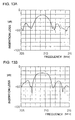
- Figs. 13A and 14A show the filter characteristics of SAW filters in which the width of the wider electrode finger of the unidirectional IDT is changed to ⁇ /6 and ⁇ /4, respectively.
- the arrangement of the split electrodes of the unidirectional IDT is the same as in Fig. 3.
- Fig. 13B and Fig. 14B show the filter characteristics of SAW filters in which the unidirectional IDT is arranged as in Fig. 19.
- Figs. 13A, 13B, 14A and 14B show that even if the width of the wider electrode finger is changed to ⁇ /6 or ⁇ /4, a low-loss SAW filter free of ripples can be produced by the arrangement shown in Fig. 3. Also a low-loss SAW filter free of ripples can be produced by the arrangement shown in Fig. 3 in the case of 36° Y - X : quartz, one of various rotated Y - X : quartz.
- the two directions agree with each other in the above description of the example, the two directions are not required to coincide with each other completely. If the angle ⁇ defined by the two directions is smaller than 90° (0 ⁇ ⁇ ⁇ 90°), good characteristics of low-loss and free of ripples can be obtained since the direction of the SAW propagation is not opposite to the direction from the narrower electrode finger to the wider electrode finger.
- the IDT provided with split electrodes composed of pairs of electrode fingers is so constructed that the direction transverse to the electrode fingers from the electrode finger having a smaller reflection factor to the electrode finger having a larger reflection factor conforms substantially with the direction in which the SAW excited by the IDT travels to the receiver IDT.
- the IDT provided with the split electrodes is so constructed such that the direction traverse to the electrode fingers from the narrower electrode finger of the split electrode to the wider electrode finger of the split electrode coincides substantially with the direction in which the SAW excited by the IDT travels to the receiver IDT.
- a SAW device having a good frequency characteristic of low-loss and free from ripples can also be obtained.
- the SAW device can have a good frequency characteristic of low-loss and free of ripples.
Landscapes
- Physics & Mathematics (AREA)
- Acoustics & Sound (AREA)
- Surface Acoustic Wave Elements And Circuit Networks Thereof (AREA)
Applications Claiming Priority (2)
| Application Number | Priority Date | Filing Date | Title |
|---|---|---|---|
| JP13198098 | 1998-05-14 | ||
| JP10131980A JPH11330895A (ja) | 1998-05-14 | 1998-05-14 | 弾性表面波装置 |
Publications (2)
| Publication Number | Publication Date |
|---|---|
| EP0957576A2 true EP0957576A2 (de) | 1999-11-17 |
| EP0957576A3 EP0957576A3 (de) | 1999-12-01 |
Family
ID=15070741
Family Applications (1)
| Application Number | Title | Priority Date | Filing Date |
|---|---|---|---|
| EP98117525A Withdrawn EP0957576A3 (de) | 1998-05-14 | 1998-09-16 | Oberflächenwellenanordnung |
Country Status (4)
| Country | Link |
|---|---|
| US (1) | US6075426A (de) |
| EP (1) | EP0957576A3 (de) |
| JP (1) | JPH11330895A (de) |
| KR (1) | KR100299087B1 (de) |
Cited By (2)
| Publication number | Priority date | Publication date | Assignee | Title |
|---|---|---|---|---|
| GB2376362A (en) * | 2001-06-06 | 2002-12-11 | Transense Technologies Plc | Sensor apparatus including unidirectional SAW device and reflector |
| US7063778B2 (en) * | 2002-01-14 | 2006-06-20 | Cambridge University Technical Services, Ltd. | Microfluidic movement |
Families Citing this family (13)
| Publication number | Priority date | Publication date | Assignee | Title |
|---|---|---|---|---|
| WO2001031782A1 (fr) * | 1999-10-18 | 2001-05-03 | Kabushiki Kaisha Toshiba | Dispositif de traitement des ondes acoustiques de surface |
| US6246150B1 (en) * | 1999-10-28 | 2001-06-12 | Kabushiki Kaisha Toshiba | Surface acoustic wave device |
| TW498614B (en) * | 1999-12-09 | 2002-08-11 | Matsushita Electric Ind Co Ltd | Elastic surface wave device and communications equipment using the elastic surface wave device |
| KR20010068299A (ko) * | 2000-01-04 | 2001-07-23 | 구자홍 | 도파관 표면탄성파 필터 |
| EP1407547A4 (de) | 2000-02-02 | 2004-04-14 | Univ Rutgers | Programmierbares oberflächenwellenfilter (saw-filter) |
| JP3414373B2 (ja) | 2000-07-26 | 2003-06-09 | 株式会社村田製作所 | 弾性表面波装置 |
| US6650206B2 (en) * | 2000-09-13 | 2003-11-18 | Matsushita Electric Industrial Co., Ltd. | Surface acoustic wave filter and communication apparatus with the same |
| US6469598B2 (en) * | 2001-03-12 | 2002-10-22 | Matsushita Electric Industrial Co., Ltd. | SAW filter with unidirectional transducer and communication apparatus using the same |
| US6806619B2 (en) * | 2001-10-16 | 2004-10-19 | Matsushita Electric Industrial Co., Ltd. | Interdigital transducer, surface acoustic wave filter, and radio communication apparatus |
| DE10314153A1 (de) * | 2003-03-28 | 2004-10-07 | Epcos Ag | Oberflächenwellen-Anordnung zur breitbandigen Signalübertragung |
| JP4527968B2 (ja) * | 2003-11-26 | 2010-08-18 | 住友ゴム工業株式会社 | 空気入りタイヤ |
| JP4561337B2 (ja) * | 2004-11-30 | 2010-10-13 | エプソントヨコム株式会社 | 一方向性弾性表面波変換器及びそれを用いた弾性表面波デバイス |
| DE102012107049B4 (de) * | 2012-08-01 | 2017-10-05 | Snaptrack, Inc. | Elektroakustischer Wandler |
Citations (4)
| Publication number | Priority date | Publication date | Assignee | Title |
|---|---|---|---|---|
| JPS616917A (ja) * | 1984-06-20 | 1986-01-13 | Kazuhiko Yamanouchi | 電極幅の変化を用いた内部反射型一方向性弾性表面波変換器 |
| WO1997010646A1 (en) * | 1995-09-15 | 1997-03-20 | Sawtek, Inc. | Weighted tapered spudt saw device |
| US5663696A (en) * | 1994-04-25 | 1997-09-02 | Advanced Saw Products Sa | Saw filter with wave reflections and phase differences |
| US5663695A (en) * | 1994-10-31 | 1997-09-02 | Ngk Insulators, Ltd. | Surface acoustic wave filter device and transducer therefor |
Family Cites Families (9)
| Publication number | Priority date | Publication date | Assignee | Title |
|---|---|---|---|---|
| JPS5944802B2 (ja) * | 1977-07-11 | 1984-11-01 | 株式会社日立製作所 | 弾性表面波素子 |
| US4162465A (en) * | 1977-09-14 | 1979-07-24 | University Of Illinois Foundation | Surface acoustic wave device with reflection suppression |
| JPS5610724A (en) * | 1979-07-09 | 1981-02-03 | Toshiba Corp | Elastic surface wave transducer |
| JPS60236312A (ja) * | 1984-05-09 | 1985-11-25 | Kazuhiko Yamanouchi | 浮き電極内部反射型一方向性弾性表面波変換器 |
| EP0166880B1 (de) * | 1984-06-05 | 1990-01-03 | Kabushiki Kaisha Toshiba | Akustische Oberflächen-Wellen-Anordnung |
| JP3175830B2 (ja) * | 1989-10-19 | 2001-06-11 | 東洋通信機株式会社 | 一方向性sawフィルタ |
| US5274345A (en) * | 1992-05-13 | 1993-12-28 | Andersen Laboratories | Dual function reflector structures for interdigital saw transducer |
| JPH08288780A (ja) * | 1995-04-10 | 1996-11-01 | Canon Inc | 弾性表面波素子とこれを用いた通信システム |
| JP3077052B2 (ja) * | 1995-12-27 | 2000-08-14 | 株式会社村田製作所 | 弾性表面波共振子フィルタ装置 |
-
1998
- 1998-05-14 JP JP10131980A patent/JPH11330895A/ja active Pending
- 1998-09-15 US US09/153,336 patent/US6075426A/en not_active Expired - Fee Related
- 1998-09-16 EP EP98117525A patent/EP0957576A3/de not_active Withdrawn
- 1998-09-29 KR KR1019980040463A patent/KR100299087B1/ko not_active IP Right Cessation
Patent Citations (4)
| Publication number | Priority date | Publication date | Assignee | Title |
|---|---|---|---|---|
| JPS616917A (ja) * | 1984-06-20 | 1986-01-13 | Kazuhiko Yamanouchi | 電極幅の変化を用いた内部反射型一方向性弾性表面波変換器 |
| US5663696A (en) * | 1994-04-25 | 1997-09-02 | Advanced Saw Products Sa | Saw filter with wave reflections and phase differences |
| US5663695A (en) * | 1994-10-31 | 1997-09-02 | Ngk Insulators, Ltd. | Surface acoustic wave filter device and transducer therefor |
| WO1997010646A1 (en) * | 1995-09-15 | 1997-03-20 | Sawtek, Inc. | Weighted tapered spudt saw device |
Non-Patent Citations (1)
| Title |
|---|
| PATENT ABSTRACTS OF JAPAN vol. 010, no. 145 (E-407), 28 May 1986 (1986-05-28) & JP 61 006917 A (KAZUHIKO YAMANOUCHI), 13 January 1986 (1986-01-13) * |
Cited By (2)
| Publication number | Priority date | Publication date | Assignee | Title |
|---|---|---|---|---|
| GB2376362A (en) * | 2001-06-06 | 2002-12-11 | Transense Technologies Plc | Sensor apparatus including unidirectional SAW device and reflector |
| US7063778B2 (en) * | 2002-01-14 | 2006-06-20 | Cambridge University Technical Services, Ltd. | Microfluidic movement |
Also Published As
| Publication number | Publication date |
|---|---|
| EP0957576A3 (de) | 1999-12-01 |
| KR19990086987A (ko) | 1999-12-15 |
| KR100299087B1 (ko) | 2001-10-27 |
| US6075426A (en) | 2000-06-13 |
| JPH11330895A (ja) | 1999-11-30 |
Similar Documents
| Publication | Publication Date | Title |
|---|---|---|
| US6075426A (en) | Surface acoustic wave device with an angle α related to specific piezoelectric substrates | |
| JP2019140456A (ja) | 弾性波装置、高周波フロントエンド回路及び通信装置 | |
| US6960866B2 (en) | Surface acoustic wave device | |
| US4237433A (en) | Surface acoustic wave resonators with integrated internal coupler reflectors | |
| JP2000183681A (ja) | 弾性表面波装置 | |
| JPH06260881A (ja) | 弾性表面波コンボルバ | |
| JPH11298286A (ja) | 弾性表面波導波路構造及びそれを用いたデバイス | |
| US5714830A (en) | Free edge reflective-type surface acoustic wave device | |
| US6600391B2 (en) | End surface reflection type surface acoustic wave apparatus utilizing waves with a longitudinal wave or shear vertical wave main component | |
| WO2023002823A1 (ja) | 弾性波装置 | |
| EP0802627A1 (de) | Akustischer oberflächenkonverter und akustisches wellenfilter damit | |
| US4810920A (en) | Acoustic surface wave multimode filter comprising a bus bar which is thicker than acoustic surface wave resonators | |
| US6147574A (en) | Unidirectional surface acoustic wave transducer and transversal-type saw filter having the same | |
| US6559738B2 (en) | Unidirectional transducer and saw filter comprising the same | |
| JPS63184411A (ja) | 弾性表面波装置 | |
| WO2024116813A1 (ja) | 弾性波装置及びフィルタ装置 | |
| JPH08204492A (ja) | 弾性表面波トランスデューサ | |
| WO2024117050A1 (ja) | 弾性波装置及びフィルタ装置 | |
| JPH0370933B2 (de) | ||
| WO2024043347A1 (ja) | 弾性波装置及びフィルタ装置 | |
| JPH08125484A (ja) | 弾性表面波デバイス | |
| JPS6382115A (ja) | 弾性表面波装置 | |
| JPH0317461Y2 (de) | ||
| JP2002223143A (ja) | 弾性表面波装置 | |
| JPH07106911A (ja) | 弾性表面波共振器および弾性表面波フィルタ |
Legal Events
| Date | Code | Title | Description |
|---|---|---|---|
| PUAI | Public reference made under article 153(3) epc to a published international application that has entered the european phase |
Free format text: ORIGINAL CODE: 0009012 |
|
| PUAL | Search report despatched |
Free format text: ORIGINAL CODE: 0009013 |
|
| AK | Designated contracting states |
Kind code of ref document: A2 Designated state(s): AT BE CH CY DE DK ES FI FR GB GR IE IT LI LU MC NL PT SE |
|
| AX | Request for extension of the european patent |
Free format text: AL;LT;LV;MK;RO;SI |
|
| AK | Designated contracting states |
Kind code of ref document: A3 Designated state(s): AT BE CH CY DE DK ES FI FR GB GR IE IT LI LU MC NL PT SE |
|
| AX | Request for extension of the european patent |
Free format text: AL;LT;LV;MK;RO;SI |
|
| RIC1 | Information provided on ipc code assigned before grant |
Free format text: 6H 03H 9/05 A, 6H 03H 9/64 B, 6H 03H 9/145 B |
|
| AKX | Designation fees paid | ||
| 17P | Request for examination filed |
Effective date: 20000522 |
|
| RBV | Designated contracting states (corrected) |
Designated state(s): DE FR |
|
| RBV | Designated contracting states (corrected) |
Designated state(s): DE FR |
|
| REG | Reference to a national code |
Ref country code: DE Ref legal event code: 8566 |
|
| STAA | Information on the status of an ep patent application or granted ep patent |
Free format text: STATUS: THE APPLICATION IS DEEMED TO BE WITHDRAWN |
|
| 18D | Application deemed to be withdrawn |
Effective date: 20070403 |