EP0957414A1 - Masse de remontage oscillante pour pièce d'horlogerie à mouvement automatique et pièce d'horlogerie équipée d'une telle masse de remontage - Google Patents
Masse de remontage oscillante pour pièce d'horlogerie à mouvement automatique et pièce d'horlogerie équipée d'une telle masse de remontage Download PDFInfo
- Publication number
- EP0957414A1 EP0957414A1 EP98108338A EP98108338A EP0957414A1 EP 0957414 A1 EP0957414 A1 EP 0957414A1 EP 98108338 A EP98108338 A EP 98108338A EP 98108338 A EP98108338 A EP 98108338A EP 0957414 A1 EP0957414 A1 EP 0957414A1
- Authority
- EP
- European Patent Office
- Prior art keywords
- winding weight
- weight according
- connecting member
- movement
- winding
- Prior art date
- Legal status (The legal status is an assumption and is not a legal conclusion. Google has not performed a legal analysis and makes no representation as to the accuracy of the status listed.)
- Granted
Links
- 238000004804 winding Methods 0.000 title claims description 30
- 239000000463 material Substances 0.000 claims abstract description 7
- 229910052594 sapphire Inorganic materials 0.000 claims abstract description 7
- 239000010980 sapphire Substances 0.000 claims abstract description 7
- 230000003287 optical effect Effects 0.000 claims description 4
- 239000011521 glass Substances 0.000 claims description 3
- 238000004026 adhesive bonding Methods 0.000 claims description 2
- 210000000056 organ Anatomy 0.000 claims 2
- 229910001080 W alloy Inorganic materials 0.000 abstract description 3
- 229910000831 Steel Inorganic materials 0.000 abstract description 2
- 239000010959 steel Substances 0.000 abstract description 2
- 229910045601 alloy Inorganic materials 0.000 abstract 1
- 239000000956 alloy Substances 0.000 abstract 1
- 208000035210 Ring chromosome 18 syndrome Diseases 0.000 description 2
- 230000002093 peripheral effect Effects 0.000 description 2
- 239000007787 solid Substances 0.000 description 2
- 238000005303 weighing Methods 0.000 description 2
- 238000002788 crimping Methods 0.000 description 1
- 229910003460 diamond Inorganic materials 0.000 description 1
- 239000010432 diamond Substances 0.000 description 1
- 230000000694 effects Effects 0.000 description 1
- 229910052751 metal Inorganic materials 0.000 description 1
- 239000002184 metal Substances 0.000 description 1
- 230000035939 shock Effects 0.000 description 1
- 239000012780 transparent material Substances 0.000 description 1
- 238000003466 welding Methods 0.000 description 1
Images


Classifications
-
- G—PHYSICS
- G04—HOROLOGY
- G04B—MECHANICALLY-DRIVEN CLOCKS OR WATCHES; MECHANICAL PARTS OF CLOCKS OR WATCHES IN GENERAL; TIME PIECES USING THE POSITION OF THE SUN, MOON OR STARS
- G04B5/00—Automatic winding up
- G04B5/02—Automatic winding up by self-winding caused by the movement of the watch
- G04B5/18—Supports, suspensions or guide arrangements, for oscillating weights
-
- G—PHYSICS
- G04—HOROLOGY
- G04B—MECHANICALLY-DRIVEN CLOCKS OR WATCHES; MECHANICAL PARTS OF CLOCKS OR WATCHES IN GENERAL; TIME PIECES USING THE POSITION OF THE SUN, MOON OR STARS
- G04B45/00—Time pieces of which the indicating means or cases provoke special effects, e.g. aesthetic effects
- G04B45/02—Time pieces of which the clockwork is visible partly or wholly
Definitions
- the present invention relates to a winding weight oscillating movement timepiece automatic. More particularly, the invention relates such a winding mass intended to equip a wristwatch with a transparent background, said mass being arranged on the side of the bottom of the box and allowing the observation of the entire movement in permanence.
- the main object of the present invention is therefore to remedy the drawbacks of the prior art mentioned above, by providing a winding mass oscillating allowing observation of the movement it team without any visible obstacle.
- the invention relates to a mass of oscillating winding for a timepiece including a heavy part fixed to a connecting member connecting said heavy part having an axis integral with a movement, said mass being intended to be rotatably mounted on said axis, characterized in that said connecting member is made of a transparent or translucent material.
- the connecting member is formed by a solid sapphire disc.
- the invention also has for object a timepiece comprising a formed case of a middle closed by a glass and a bottom at least partially transparent and in which is housed a automatic watch movement, characterized in that said movement is equipped with a oscillating winding weight as defined above.
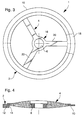
- FIGS. 1 and 2 show a first mode of realization of an oscillating winding weight according to the invention, designated by the general reference 1.
- This mass is intended to classically equip the movement to automatic winding of a timepiece (not shown) and including in particular a box formed of a middle closed by a glass and a bottom at least partially transparent to make the movement visible from the bottom.
- the winding weight 1 includes a heavy part 2 attached to a connecting member 4 connecting the heavy part to an axis (not shown) integral with a movement of watchmaking, mass 1 being intended to be mounted at rotation on this axis.
- the liaison body has in its center an opening 6 in which is driven out a ring 8 forming the hub of the mass 1.
- the connecting member 4 is formed a solid disc made of a transparent material such that the sapphire which allows to observe the movement at through mass 1. It goes without saying that any other transparent or translucent material, synthetic or natural can be used. In all cases, the material must at least allow the passage of light to ability to distinguish shapes from elements behind.
- the heavy part 2 comprises a ring 10 which has an unbalance 12 on an arc of about 180 ° which is formed by an extra thickness of said ring 10.
- the ring 10 and the unbalance 12 are made in one piece.
- the part weighing 2 is made of a high density metal, by example, a tungsten alloy.
- the unbalance 12 can be attached to the ring 10 by any fixing means conventional such as screwing, gluing, crimping, welding or similar.
- the ring 10 can be made in an easily machinable material such as steel, and unbalance 12 in a tungsten alloy.
- the ring 10 includes a rebate 14 in which the disc 4 is engaged and glued.
- this disc 4 can be fixed in the rebate 14 of the ring 10 by any other means conventional fastening such as screwing, riveting or similar.
- FIG 3 there is shown a second mode of realization of an oscillating winding weight 1 according to the invention.
- elements identical to those described in connection with Figures 1 and 2 have been designated by the same references digital.
- the ring 8 forming the hub of the mass 1 has been omitted in Figure 3.
- the connecting member 4 of this mode of realization consists of a partially hollowed out disc also in sapphire. More specifically, the liaison body 4 includes a central part 16 provided with the opening 6 and a peripheral ring 18 concentric with the opening 6, the central part 16 being connected to the peripheral ring 18 by three arms 20.
- the recesses of the disc 4 will be advantageously made using diamond grinding wheels or again using a laser beam.
- FIG. 4 shows a third mode of realization of an oscillating winding weight 1 according to the invention in which the connecting member 4 is formed of a circular magnifying optical lens. It goes from so that according to variant embodiments, any other type of optical lens can be considered. We will be able to especially provide Fresnel lenses that have the peculiarity of being flatter than a conventional lens for a given magnification. We could still consider to use 4 lenses for these connecting members producing kaleidoscopic effects.
- Figures 5 and 6 show a fourth mode of an oscillating winding weight 1 of the invention in which the connecting member 4 is formed a transparent plate shaped in the angular sector extending over approximately 180 ° and in which the part weighing 2 is formed by a ring portion extending to the periphery of plate 4 on an arc about 180 °.
- Plate 4 is made of sapphire and further includes a magnifying optical lens 22 which extends radially from ring 8 to the ring of the heavy part 2.
- FIG. 7 shows a fifth mode of realization of an oscillating winding weight 1 according to the invention in which the connecting member 4 is formed a transparent plate in the shape of an angular sector extending about 180 ° and including at its periphery a flange 24 folded at an angle.
- the heavy part 2 is also formed by a part ring extending over an arc of approximately 180 ° and fixed by means of screws 26 on the inner face 28 of the ledge 24.
- this embodiment of the winding mass 1 allows, thanks to its folded rim 24, to adapt as best as possible to the external shape of the movement that it is intended to equip, it being understood that the rim 24 is folded in the direction of movement.
Landscapes
- Physics & Mathematics (AREA)
- General Physics & Mathematics (AREA)
- Electromechanical Clocks (AREA)
- Toys (AREA)
- Electric Clocks (AREA)
- Apparatuses For Generation Of Mechanical Vibrations (AREA)
Abstract
Description
- la figure 1 est une vue en plan d'un premier mode de réalisation d'une masse de remontage oscillante selon l'invention;
- la figure 2 est une coupe selon la ligne II-II de la figure 1;
- la figure 3 est une vue en plan d'un deuxième de mode réalisation d'une masse de remontage oscillante selon l'invention;
- la figure 4 est une coupe, similaire à celle représentée à la figure 2, d'un troisième mode de réalisation selon l'invention;
- la figure 5 est une vue en plan d'un quatrième mode de réalisation d'une masse de remontage oscillante selon l'invention;
- la figure 6 est une coupe partielle selon la ligne VI-VI de la figure 5; et
- la figure 7 est une coupe d'un cinquième mode de réalisation selon l'invention.
Claims (10)
- Masse de remontage oscillante pour pièce d'horlogerie comprenant une partie pesante fixée à un organe de liaison reliant ladite partie pesante à un axe solidaire d'un mouvement, ladite masse étant destinée à être montée à rotation sur ledit axe, caractérisée en ce que ledit organe de liaison est réalisé en un matériau transparent ou translucide.
- Masse de remontage selon la revendication 1, caractérisée en ce que ledit organe de liaison est formé d'un disque plein.
- Masse de remontage selon la revendication 1, caractérisée en ce que ledit organe de liaison est formé d'un disque au moins partiellement évidé.
- Masse de remontage selon la revendication 1 ou 3, caractérisée en ce que ledit organe de liaison est formé d'au moins deux bras de liaison.
- Masse de remontage selon l'une des revendications précédentes, caractérisée en ce que ledit organe de liaison est réalisé en saphir.
- Masse de remontage selon l'une des revendications précédentes, caractérisée en ce que ledit organe de liaison comporte une lentille optique.
- Masse de remontage selon l'une des revendications précédentes, caractérisée en ce que ladite partie pesante est formée d'une partie d'anneau s'étandant sur un arc de cercle d'environ 180°.
- Masse de remontage selon l'une des revendications 1 à 6, caractérisée en ce que ladite partie pesante est formée d'un anneau circulaire comportant, sur un arc de cercle d'environ 180°, un balourd.
- Masse de remontage selon l'une des revendications précédente, caractérisée en ce que ladite partie pesante est fixée audit organe de liaison par collage.
- Pièce d'horlogerie comportant une boíte formée d'une carrure fermée par une glace et un fond au moins partiellement transparent et dans laquelle est logé un mouvement d'horlogerie à remontage automatique, caractérisée en ce que ledit mouvement est équipée d'une masse de remontage oscillante selon l'une quelconque des revendications 1 à 9.
Priority Applications (6)
| Application Number | Priority Date | Filing Date | Title |
|---|---|---|---|
| DE69811338T DE69811338T2 (de) | 1998-05-07 | 1998-05-07 | Schwungmasse für Uhren mit selbstaufziehendem Uhrwerk und damit ausgestattete Uhr |
| EP98108338A EP0957414B1 (fr) | 1998-05-07 | 1998-05-07 | Masse de remontage oscillante pour pièce d'horlogerie à mouvement automatique et pièce d'horlogerie équipée d'une telle masse de remontage |
| CNB998007064A CN1175323C (zh) | 1998-05-07 | 1999-04-30 | 用于自动钟表元件的上发条摆锤和装有该摆锤的钟表元件 |
| US09/462,359 US6354731B1 (en) | 1998-05-07 | 1999-04-30 | Oscillating winding weight for a timepiece with an automatic movement and timepiece fitted with such a winding weight |
| PCT/EP1999/002936 WO1999057613A1 (fr) | 1998-05-07 | 1999-04-30 | Masse de remontage oscillante pour piece d'horlogerie a mouvement automatique et piece d'horlogerie equipee d'une telle masse de remontage |
| JP2000547523A JP2002513944A (ja) | 1998-05-07 | 1999-04-30 | 自動可動部を有する時計用の振動巻上げ重りおよびそのような巻上げ重りを備えた時計 |
Applications Claiming Priority (1)
| Application Number | Priority Date | Filing Date | Title |
|---|---|---|---|
| EP98108338A EP0957414B1 (fr) | 1998-05-07 | 1998-05-07 | Masse de remontage oscillante pour pièce d'horlogerie à mouvement automatique et pièce d'horlogerie équipée d'une telle masse de remontage |
Publications (2)
| Publication Number | Publication Date |
|---|---|
| EP0957414A1 true EP0957414A1 (fr) | 1999-11-17 |
| EP0957414B1 EP0957414B1 (fr) | 2003-02-12 |
Family
ID=8231894
Family Applications (1)
| Application Number | Title | Priority Date | Filing Date |
|---|---|---|---|
| EP98108338A Expired - Lifetime EP0957414B1 (fr) | 1998-05-07 | 1998-05-07 | Masse de remontage oscillante pour pièce d'horlogerie à mouvement automatique et pièce d'horlogerie équipée d'une telle masse de remontage |
Country Status (6)
| Country | Link |
|---|---|
| US (1) | US6354731B1 (fr) |
| EP (1) | EP0957414B1 (fr) |
| JP (1) | JP2002513944A (fr) |
| CN (1) | CN1175323C (fr) |
| DE (1) | DE69811338T2 (fr) |
| WO (1) | WO1999057613A1 (fr) |
Cited By (4)
| Publication number | Priority date | Publication date | Assignee | Title |
|---|---|---|---|---|
| WO2006116201A3 (fr) * | 2005-04-26 | 2007-09-13 | Fossil Partners L P | Piece d'horlogerie a remontage automatique |
| WO2008135817A2 (fr) | 2007-05-08 | 2008-11-13 | Patek, Philippe Sa | Composant horloger et son procédé de fabrication |
| EP3428737A1 (fr) | 2017-07-11 | 2019-01-16 | ETA SA Manufacture Horlogère Suisse | Masse de remontage oscillante pour pièce d'horlogerie à mouvement automatique et pièce d'horlogerie équipée d'une telle masse de remontage |
| EP3839646A1 (fr) | 2019-12-18 | 2021-06-23 | The Swatch Group Research and Development Ltd | Masse de remontage oscillante munie d'un element decoratif pour mouvement automatique de pièce d'horlogerie |
Families Citing this family (24)
| Publication number | Priority date | Publication date | Assignee | Title |
|---|---|---|---|---|
| CH705048B1 (fr) * | 2002-07-09 | 2012-12-14 | Lvmh Swiss Mft Sa | Dispositif d'entraînement par courroies lisses ou crantées d'un mouvement de montre mécanique. |
| EP1445668B1 (fr) * | 2003-02-04 | 2009-07-15 | Vaucher Manufacture Fleurier SA | Masse oscillante |
| WO2005054961A1 (fr) * | 2003-12-02 | 2005-06-16 | Luca Freudiger | Poids excentrique oscillant destine au systeme de remontage automatique d'une piece d'horlogerie, et permettant d'observer le mecanisme de la piece d'horlogerie |
| EP1672441A1 (fr) * | 2004-12-14 | 2006-06-21 | Giuseppe Chines | Cadran de montre avec masses oscillantes |
| JP4631839B2 (ja) * | 2006-02-22 | 2011-02-16 | セイコーエプソン株式会社 | 時計 |
| US8475034B2 (en) * | 2006-04-12 | 2013-07-02 | The Long Now Foundation | Enhanced compound pendulums and systems |
| US20070283586A1 (en) * | 2006-04-12 | 2007-12-13 | Hillis W D | Low-Displacement Pendulum |
| US8240910B2 (en) * | 2006-12-21 | 2012-08-14 | Complitime S.A. | Mechanical oscillator for timepiece |
| EP2104005A1 (fr) * | 2008-03-20 | 2009-09-23 | Nivarox-FAR S.A. | Balancier composite et son procédé de fabrication |
| EP2104008A1 (fr) * | 2008-03-20 | 2009-09-23 | Nivarox-FAR S.A. | Organe régulateur monobloc et son procédé de fabrication |
| USD640582S1 (en) * | 2009-12-01 | 2011-06-28 | Lvmh Swiss Manufactures S.A. | Weight |
| EP2410386B1 (fr) * | 2010-07-19 | 2018-10-03 | Nivarox-FAR S.A. | Balancier à réglage d'inertie avec insert |
| CH703577B1 (fr) * | 2011-03-23 | 2015-10-15 | Christian Dior Couture Sa | Masse oscillante pour montre automatique et montre automatique comportant une telle masse. |
| EP2592498A1 (fr) * | 2011-11-08 | 2013-05-15 | ETA SA Manufacture Horlogère Suisse | Masse oscillante |
| CH706000B1 (fr) * | 2012-01-13 | 2023-09-15 | Christian Dior Couture Sa | Masse de remontage. |
| JP5964089B2 (ja) * | 2012-03-07 | 2016-08-03 | セイコーインスツル株式会社 | 時計用回転錘および時計用回転錘を備えた時計 |
| CN203287693U (zh) * | 2012-11-16 | 2013-11-13 | 石志鹏 | 一种新型手表机芯 |
| CN105103058B (zh) * | 2013-04-10 | 2018-04-10 | 斯沃奇集团研究和开发有限公司 | 用于具有自动上条机构的表的上条装置 |
| USD759527S1 (en) * | 2013-10-16 | 2016-06-21 | Swatch Ltd | Oscillating weight |
| EP3865953A1 (fr) * | 2020-02-17 | 2021-08-18 | The Swatch Group Research and Development Ltd | Masse de remontage oscillante munie d'un element decoratif rotatif pour mouvement automatique d'une piece d'horlogerie |
| EP3879354B1 (fr) * | 2020-03-09 | 2025-07-30 | The Swatch Group Research and Development Ltd | Masse de remontage oscillante munie d'un element decoratif pour mouvement automatique de pièce d'horlogerie |
| USD937944S1 (en) | 2020-07-28 | 2021-12-07 | Coulter Ventures, Llc. | Weight plate |
| USD1033574S1 (en) | 2021-06-29 | 2024-07-02 | Coulter Ventures, Llc. | Weight plate |
| LU504394B1 (fr) | 2023-06-01 | 2024-12-09 | Global Capital Link Soparfi S A R L | Piece d'horlogerie a mouvement automatique |
Citations (1)
| Publication number | Priority date | Publication date | Assignee | Title |
|---|---|---|---|---|
| EP0360140A1 (fr) * | 1988-09-23 | 1990-03-28 | Eta SA Fabriques d'Ebauches | Montre-squelette laissant voir tout ou partie des organes dont elle est constituée |
Family Cites Families (7)
| Publication number | Priority date | Publication date | Assignee | Title |
|---|---|---|---|---|
| US2936571A (en) * | 1956-02-10 | 1960-05-17 | Hamilton Watch Co | Counterbalance for balance wheel |
| CH1635773A4 (fr) * | 1973-11-21 | 1976-12-15 | ||
| US3942317A (en) * | 1974-12-03 | 1976-03-09 | Ebauches Bettlach S.A. | Component parts for watch movements |
| CH590505B5 (fr) * | 1975-05-30 | 1977-08-15 | Ebauchesfabrik Eta Ag | |
| CH649185GA3 (fr) * | 1983-07-08 | 1985-05-15 | ||
| CH676185B5 (fr) * | 1989-06-01 | 1991-06-28 | Piguet Frederic Sa | |
| CH692874A5 (fr) * | 1997-11-20 | 2002-11-29 | Ebauchesfabrik Eta Ag | Instrument de petit volume muni d'un dispositif de limitation de la puissance mécanique fournie par une masse oscillante. |
-
1998
- 1998-05-07 EP EP98108338A patent/EP0957414B1/fr not_active Expired - Lifetime
- 1998-05-07 DE DE69811338T patent/DE69811338T2/de not_active Expired - Fee Related
-
1999
- 1999-04-30 JP JP2000547523A patent/JP2002513944A/ja active Pending
- 1999-04-30 WO PCT/EP1999/002936 patent/WO1999057613A1/fr not_active Ceased
- 1999-04-30 US US09/462,359 patent/US6354731B1/en not_active Expired - Lifetime
- 1999-04-30 CN CNB998007064A patent/CN1175323C/zh not_active Expired - Fee Related
Patent Citations (1)
| Publication number | Priority date | Publication date | Assignee | Title |
|---|---|---|---|---|
| EP0360140A1 (fr) * | 1988-09-23 | 1990-03-28 | Eta SA Fabriques d'Ebauches | Montre-squelette laissant voir tout ou partie des organes dont elle est constituée |
Non-Patent Citations (1)
| Title |
|---|
| "Erstarrte Fronten durchbrechen", UHREN -JUWELEN-SCHMUCK, vol. 38, no. 23, December 1983 (1983-12-01), Bielefeld,Allemagne, pages 22, XP002082475 * |
Cited By (8)
| Publication number | Priority date | Publication date | Assignee | Title |
|---|---|---|---|---|
| WO2006116201A3 (fr) * | 2005-04-26 | 2007-09-13 | Fossil Partners L P | Piece d'horlogerie a remontage automatique |
| WO2008135817A2 (fr) | 2007-05-08 | 2008-11-13 | Patek, Philippe Sa | Composant horloger et son procédé de fabrication |
| WO2008135817A3 (fr) * | 2007-05-08 | 2009-04-30 | Patek Philippe Sa | Composant horloger et son procédé de fabrication |
| CN101675392B (zh) * | 2007-05-08 | 2013-02-06 | 百达翡丽日内瓦公司 | 时钟部件及其制造方法 |
| US8636403B2 (en) | 2007-05-08 | 2014-01-28 | Patek Philippe Sa Geneve | Timepiece component and method for making same |
| US9342053B2 (en) | 2007-05-08 | 2016-05-17 | Patek Philippe Sa Geneve | Method for making a timepiece component |
| EP3428737A1 (fr) | 2017-07-11 | 2019-01-16 | ETA SA Manufacture Horlogère Suisse | Masse de remontage oscillante pour pièce d'horlogerie à mouvement automatique et pièce d'horlogerie équipée d'une telle masse de remontage |
| EP3839646A1 (fr) | 2019-12-18 | 2021-06-23 | The Swatch Group Research and Development Ltd | Masse de remontage oscillante munie d'un element decoratif pour mouvement automatique de pièce d'horlogerie |
Also Published As
| Publication number | Publication date |
|---|---|
| JP2002513944A (ja) | 2002-05-14 |
| DE69811338D1 (de) | 2003-03-20 |
| CN1175323C (zh) | 2004-11-10 |
| WO1999057613A1 (fr) | 1999-11-11 |
| DE69811338T2 (de) | 2003-12-11 |
| CN1269026A (zh) | 2000-10-04 |
| EP0957414B1 (fr) | 2003-02-12 |
| US6354731B1 (en) | 2002-03-12 |
Similar Documents
| Publication | Publication Date | Title |
|---|---|---|
| EP0957414B1 (fr) | Masse de remontage oscillante pour pièce d'horlogerie à mouvement automatique et pièce d'horlogerie équipée d'une telle masse de remontage | |
| EP3428737B1 (fr) | Masse de remontage oscillante pour pièce d'horlogerie à mouvement automatique et pièce d'horlogerie équipée d'une telle masse de remontage | |
| EP2469357B2 (fr) | Palier amortisseur de chocs pour un mobile tournant d'un mouvement d'horlogerie | |
| EP4383017A1 (fr) | Dispositif d'articulation de deux composants horlogers | |
| CH705112B1 (fr) | Palier amortisseur de chocs pour pièce d'horlogerie. | |
| EP4392834A1 (fr) | Pièce d'horlogerie comprenant un cadran présentant au moins une fenêtre et un dispositif d'obturation de ladite fenêtre | |
| FR2784203A1 (fr) | Mecanisme d'horlogerie incluant un tourbillon | |
| EP3712714B1 (fr) | Cadran pour une montre universelle | |
| EP2407832B1 (fr) | Mouvement de pièce d'horologerie | |
| CH705464B1 (fr) | Virole de fixation d'un spiral d'horlogerie. | |
| EP3779606B1 (fr) | Montre à remontage automatique | |
| CH713966A2 (fr) | Masse de remontage oscillante pour pièce d'horlogerie à mouvement automatique et pièce d'horlogerie équipée d'une telle masse de remontage. | |
| WO2021121713A1 (fr) | Masse de remontage oscillante munie d'un element decoratif pour mouvement automatique de piece d'horlogerie | |
| EP4264379B1 (fr) | Mouvement mecanique comprenant un dispositif d'affichage d'une information | |
| LU504394B1 (fr) | Piece d'horlogerie a mouvement automatique | |
| CH716774B1 (fr) | Dispositif horloger de couplage et d'indexation. | |
| EP3714336B1 (fr) | Maintien d'un mobile portant un disque d'affichage | |
| CH716502A2 (fr) | Mouvement d'horlogerie mécanique à remontage automatique. | |
| CH716973A2 (fr) | Masse de remontage oscillante munie d'un élément décoratif pour mouvement automatique de pièce d'horlogerie. | |
| EP4244680A1 (fr) | Lunette tournante pour boîte de pièce d'horlogerie | |
| CH720809B1 (fr) | Cage de tourbillon | |
| CH698028B1 (fr) | Montre à tourbillon dont la cage est entourée d'un intervalle annulaire traversé par des éléments transparents. | |
| CH715978A2 (fr) | Cadran pour une montre universelle. | |
| CH722198A2 (fr) | Pièce d'horlogerie comprenant un compteur d'une unité de temps | |
| EP3916489A1 (fr) | Ressort d'amortisseur, corps de palier et palier pour piece d'horlogerie |
Legal Events
| Date | Code | Title | Description |
|---|---|---|---|
| PUAI | Public reference made under article 153(3) epc to a published international application that has entered the european phase |
Free format text: ORIGINAL CODE: 0009012 |
|
| AK | Designated contracting states |
Kind code of ref document: A1 Designated state(s): CH DE FR GB IT LI |
|
| AX | Request for extension of the european patent |
Free format text: AL;LT;LV;MK;RO;SI |
|
| 17P | Request for examination filed |
Effective date: 20000517 |
|
| AKX | Designation fees paid |
Free format text: CH DE FR GB IT LI |
|
| GRAG | Despatch of communication of intention to grant |
Free format text: ORIGINAL CODE: EPIDOS AGRA |
|
| 17Q | First examination report despatched |
Effective date: 20020308 |
|
| GRAG | Despatch of communication of intention to grant |
Free format text: ORIGINAL CODE: EPIDOS AGRA |
|
| GRAG | Despatch of communication of intention to grant |
Free format text: ORIGINAL CODE: EPIDOS AGRA |
|
| GRAH | Despatch of communication of intention to grant a patent |
Free format text: ORIGINAL CODE: EPIDOS IGRA |
|
| GRAH | Despatch of communication of intention to grant a patent |
Free format text: ORIGINAL CODE: EPIDOS IGRA |
|
| GRAA | (expected) grant |
Free format text: ORIGINAL CODE: 0009210 |
|
| AK | Designated contracting states |
Designated state(s): CH DE FR GB IT LI |
|
| REG | Reference to a national code |
Ref country code: GB Ref legal event code: FG4D Free format text: NOT ENGLISH |
|
| REG | Reference to a national code |
Ref country code: CH Ref legal event code: EP |
|
| REF | Corresponds to: |
Ref document number: 69811338 Country of ref document: DE Date of ref document: 20030320 Kind code of ref document: P |
|
| GBT | Gb: translation of ep patent filed (gb section 77(6)(a)/1977) | ||
| REG | Reference to a national code |
Ref country code: CH Ref legal event code: NV Representative=s name: ICB INGENIEURS CONSEILS EN BREVETS SA |
|
| PLBE | No opposition filed within time limit |
Free format text: ORIGINAL CODE: 0009261 |
|
| STAA | Information on the status of an ep patent application or granted ep patent |
Free format text: STATUS: NO OPPOSITION FILED WITHIN TIME LIMIT |
|
| 26N | No opposition filed |
Effective date: 20031113 |
|
| PGFP | Annual fee paid to national office [announced via postgrant information from national office to epo] |
Ref country code: IT Payment date: 20090424 Year of fee payment: 12 Ref country code: FR Payment date: 20090527 Year of fee payment: 12 Ref country code: DE Payment date: 20090603 Year of fee payment: 12 |
|
| PGFP | Annual fee paid to national office [announced via postgrant information from national office to epo] |
Ref country code: GB Payment date: 20090427 Year of fee payment: 12 |
|
| GBPC | Gb: european patent ceased through non-payment of renewal fee |
Effective date: 20100507 |
|
| REG | Reference to a national code |
Ref country code: FR Ref legal event code: ST Effective date: 20110131 |
|
| PG25 | Lapsed in a contracting state [announced via postgrant information from national office to epo] |
Ref country code: IT Free format text: LAPSE BECAUSE OF NON-PAYMENT OF DUE FEES Effective date: 20100507 |
|
| PG25 | Lapsed in a contracting state [announced via postgrant information from national office to epo] |
Ref country code: DE Free format text: LAPSE BECAUSE OF NON-PAYMENT OF DUE FEES Effective date: 20101201 |
|
| PG25 | Lapsed in a contracting state [announced via postgrant information from national office to epo] |
Ref country code: FR Free format text: LAPSE BECAUSE OF NON-PAYMENT OF DUE FEES Effective date: 20100531 |
|
| PG25 | Lapsed in a contracting state [announced via postgrant information from national office to epo] |
Ref country code: GB Free format text: LAPSE BECAUSE OF NON-PAYMENT OF DUE FEES Effective date: 20100507 |
|
| PGFP | Annual fee paid to national office [announced via postgrant information from national office to epo] |
Ref country code: CH Payment date: 20160621 Year of fee payment: 19 |
|
| REG | Reference to a national code |
Ref country code: CH Ref legal event code: PL |
|
| PG25 | Lapsed in a contracting state [announced via postgrant information from national office to epo] |
Ref country code: LI Free format text: LAPSE BECAUSE OF NON-PAYMENT OF DUE FEES Effective date: 20170531 Ref country code: CH Free format text: LAPSE BECAUSE OF NON-PAYMENT OF DUE FEES Effective date: 20170531 |