EP0957321B1 - Luftbefeuchtungsanlage - Google Patents
Luftbefeuchtungsanlage Download PDFInfo
- Publication number
- EP0957321B1 EP0957321B1 EP99109153A EP99109153A EP0957321B1 EP 0957321 B1 EP0957321 B1 EP 0957321B1 EP 99109153 A EP99109153 A EP 99109153A EP 99109153 A EP99109153 A EP 99109153A EP 0957321 B1 EP0957321 B1 EP 0957321B1
- Authority
- EP
- European Patent Office
- Prior art keywords
- nozzle
- baffle
- baffles
- air
- nozzles
- Prior art date
- Legal status (The legal status is an assumption and is not a legal conclusion. Google has not performed a legal analysis and makes no representation as to the accuracy of the status listed.)
- Expired - Lifetime
Links
- XLYOFNOQVPJJNP-UHFFFAOYSA-N water Substances O XLYOFNOQVPJJNP-UHFFFAOYSA-N 0.000 claims abstract description 24
- 239000007921 spray Substances 0.000 claims abstract description 6
- 238000009692 water atomization Methods 0.000 claims description 3
- 238000011144 upstream manufacturing Methods 0.000 abstract description 2
- 238000004519 manufacturing process Methods 0.000 description 7
- 238000010276 construction Methods 0.000 description 4
- 238000000034 method Methods 0.000 description 4
- 238000010521 absorption reaction Methods 0.000 description 3
- 230000000903 blocking effect Effects 0.000 description 3
- 239000000463 material Substances 0.000 description 3
- 238000004378 air conditioning Methods 0.000 description 2
- 230000000694 effects Effects 0.000 description 2
- 239000010979 ruby Substances 0.000 description 2
- 229910001750 ruby Inorganic materials 0.000 description 2
- 241001599630 Stelis <bee> Species 0.000 description 1
- 239000000428 dust Substances 0.000 description 1
- 230000002349 favourable effect Effects 0.000 description 1
- 230000003993 interaction Effects 0.000 description 1
- 239000007788 liquid Substances 0.000 description 1
- 239000003595 mist Substances 0.000 description 1
- 239000002245 particle Substances 0.000 description 1
Images


Classifications
-
- F—MECHANICAL ENGINEERING; LIGHTING; HEATING; WEAPONS; BLASTING
- F24—HEATING; RANGES; VENTILATING
- F24F—AIR-CONDITIONING; AIR-HUMIDIFICATION; VENTILATION; USE OF AIR CURRENTS FOR SCREENING
- F24F6/00—Air-humidification, e.g. cooling by humidification
- F24F6/12—Air-humidification, e.g. cooling by humidification by forming water dispersions in the air
- F24F6/14—Air-humidification, e.g. cooling by humidification by forming water dispersions in the air using nozzles
-
- Y—GENERAL TAGGING OF NEW TECHNOLOGICAL DEVELOPMENTS; GENERAL TAGGING OF CROSS-SECTIONAL TECHNOLOGIES SPANNING OVER SEVERAL SECTIONS OF THE IPC; TECHNICAL SUBJECTS COVERED BY FORMER USPC CROSS-REFERENCE ART COLLECTIONS [XRACs] AND DIGESTS
- Y02—TECHNOLOGIES OR APPLICATIONS FOR MITIGATION OR ADAPTATION AGAINST CLIMATE CHANGE
- Y02B—CLIMATE CHANGE MITIGATION TECHNOLOGIES RELATED TO BUILDINGS, e.g. HOUSING, HOUSE APPLIANCES OR RELATED END-USER APPLICATIONS
- Y02B30/00—Energy efficient heating, ventilation or air conditioning [HVAC]
- Y02B30/54—Free-cooling systems
Definitions
- the invention relates to an air humidification system according to the Preamble of claim 1.
- Humidifiers are used in a flow channel arranged for the air to be humidified.
- the flowing past Air is drawn from the side by side Atomizer nozzles enriched with atomized water. Also at This type of humidification is water absorption only possible to a limited extent.
- Another way of air humidification is based on a Airflow duct performed by placing air baffles in corresponding positions are arranged at which also Spray nozzles for the introduction of liquid at various Places in the airflow channel are arranged.
- This type of Humidification flows through the air to be humidified Airflow duct, the air flowing through the mold the baffles arranged in the air flow channel is deflected.
- These guide plates are also referred to as guide vanes, and direct the air from a shape based on its shape in the airflow duct laminar flow around.
- an air flow duct is required, which is provided by appropriate Boundary walls is formed.
- the so-called guide vanes are in this air flow channel inserted or mounted in the openings provided, and in such a way that they are in the walls of the Completely close the openings provided for the air flow channel.
- the so-called Guide vanes By flowing the air through the airflow duct So through the shape of the air baffles, the so-called Guide vanes have a swirl on the flowing air stream causes.
- the arranged in the middle of the guide vanes Spray nozzles humidify the air flowing through and this is caused by the swirling of the air baffles or so-called guide vanes enriched with moisture than in the previously described methods.
- the patent DE 42 29 172 C1 is also one Device for humidifying an air flow with nozzles and Airflow blocking elements have become known, in which several Nozzles for water atomization evenly over the Cross section of the air flow channel are arranged.
- the Airflow blocking element which is upstream or downstream can be arranged in the air flow channel, air passage openings introduced to guide the air.
- the spray Jets the water in the direction of air flow.
- the nozzles are in relation to the air passage openings of the air flow blocking element arranged so that each nozzle one Air passage opening is assigned and approximately in the middle of it lies.
- the invention is based on the object Air humidifier to produce a higher Efficiency with more favorable mixing of air and water guaranteed and is much easier to manufacture has greater stability and in addition the Manufacturing costs reduced.
- An essential feature here is that several nozzles for the Water atomization and several baffle plates evenly over the Cross section of the air flow channel are arranged, and the Nozzles spray the water with the flow direction of the air, wherein at least one nozzle is assigned to a baffle plate is, and the nozzles downstream to the baffles and in essentially radially inward with respect to the lateral surface of the Baffle plate are in the slipstream of the Flapper.
- a nozzle rake presented a very simple bracket for baffle plates having.
- the baffle plates are used to generate Air vortices that atomized the behind the baffles Take up and take away water particles.
- the baffle plates cause contrary to the arrangement described above, in which the Air is deflected, a swirl of the air flowing through of the airflow duct. This means that the baffle plates create the side thereof facing away from the air flow direction Negative pressure, the absorption of the atomized water favored.
- the Atomizer nozzle in the center of the generated by the swirl Turbulence of the respective flapper in the air flow of the Air flow channel is arranged.
- this atomizer nozzle in the turbulence chamber behind the baffle to achieve the baffle plate by a Baffle plate holder in cooperation with Steli screws in appropriate distance from the nozzle.
- This arrangement is designed to match the construction Turbulence ratios of different pressure ranges, both the air flow, as well as the water supplied. The adjustment takes place in that the distance between the Position of the nozzle and the baffle plate increased accordingly or reduced.
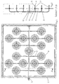
- FIG. 1 shows a possible embodiment the present invention as shown in a cross section of a Air flow channel is arranged.
- Figure 2 shows a sectional view of Figure 1, in however, the frame of the air flow channel 11 is not drawn is. It is only the arrangement of the nozzle feed lines 2 that Nozzle holder branch 3, the nozzle 4 and the Flapper bracket 6, the set screws 7 and so attached baffle plate 8 recognizable. Furthermore is in the middle 2 shows the approximately rectangular base of the Fastening plate 10 of the main feed line 1 can be seen.
- the Main supply line 1 is exactly in the middle of Figure 2 as a circle shown.
- FIG. 3 shows an example of the connection of the main feed line 1 with the pump connection 9 and the termination of the main supply line 1 with the mounting plate 10 with the main lead 1 and the parts of the humidifier attached to the Inner wall of the air flow channel 11 are attached. Furthermore is the junction between main supply line 1 and nozzle supply line 2 with the attached to the nozzle holder branches 3 Impact plates 8 shown.
- Impact plates 8 shown in the baffles 8 are radial, radial and at an angle to each other offset elongated grooves as air passage openings 15 introduced the undesirable effect of backflow prevents the air up to the baffle plate 8.
- FIG 4 is the attachment of the baffle plates 8 in the form the baffle plate holder 6 with the two set screws 7 shown.
- the baffle plates 8 are approximately concentric arranged on the nozzle receptacle branch 3. Furthermore is shown how the nozzle 4 with the nozzle receptacle branch 3 is arranged on the nozzle feed line. It can be seen that the distance between the fixed nozzle 4 and the Baffle plate 8 variably adjustable via the set screws 7 is.
- FIG. 5 shows a partial section of the present invention, in which the nozzle 4 via a nozzle holder 5 in the Nozzle holder branch 3 is arranged, namely directly in the Swirling area behind the baffle 8.
- Figure 6 the embodiment of Figure 5 is in the Side view, seen from the nozzle 4, shown.
- the nozzle feed line 2 is seen in the direction of the air flow the baffle plate 8, the at its outlet opening Nozzle receptacle branch 3, in which the nozzle 4th is introduced.
- This nozzle 4 itself consists of a base body, which as Screw and is made of an impact body (e.g. ruby), which atomizes the water emerging from the nozzle 4 13 serves and on a guided in a 180 ° arc on Base body is attached.
- the water 13 thus emerges from the Nozzle 4 with high pressure and hits the impact body Nozzle 4 so that the water 13 is atomized finely.
- the water 13 atomized in this way from the nozzle is removed from the Air vortices 12 detected, and thus humidifies the flowing Air in the airflow duct.
- the nozzle 4 is custom-made, at the opening for the calibration of the atomized water jet a ruby is inserted. Through this calibration in Interaction with the variable setting of the distance between nozzle 4 and baffle plate 8, it is possible to achieve an optimal Humidification of the air flowing through the air flow channel to reach.
- Advantages of the illustrated invention are low Manufacturing costs, low tooling costs and through that simple arrangement, a free choice of which to use Material. It is therefore possible to use without flammable material to carry out the construction. this has the advantage that when used in air conditioning harmful emissions can be avoided.
Landscapes
- Chemical & Material Sciences (AREA)
- Engineering & Computer Science (AREA)
- Dispersion Chemistry (AREA)
- Combustion & Propulsion (AREA)
- Mechanical Engineering (AREA)
- General Engineering & Computer Science (AREA)
- Air Humidification (AREA)
- Two-Way Televisions, Distribution Of Moving Picture Or The Like (AREA)
- Air Conditioning Control Device (AREA)
Description
- Figur 1:
- Einen Querschnitt eines Luftstromkanals mit darin angeordneter Befeuchtungseinrichtung;
- Figur 2:
- Seitenansicht der Befeuchtungseinrichtung aus Figur 1;
- Figur 3:
- einen Detailausschnitt der Befeuchtungseinrichtung aus Figur 1;
- Figur 4:
- Seitenansicht des Detailausschnitts aus Figur 3;
- Figur 5:
- Seitenansicht einer Ausführungsform einer Düsenaufnahme mit eingebauter Düse und montierter Prallplatte.
- Figur 6:
- Seitenansicht der Ausführungsform nach Figur 5.
- 1.
- Hauptzuleitung
- 2.
- Düsenzuleitung
- 3.
- Düsenaufnahme-Abzweigung
- 4.
- Düse
- 5.
- Düsenaufnahme
- 6.
- Prallplattenhalterung
- 7.
- Stellschrauben
- 8.
- Prallplatte
- 9.
- Pumpenanschluß
- 10.
- Befestigungsblech
- 11.
- Luftstromkanal
- 12.
- Luftwirbel
- 13.
- zerstäubtes Wasser
- 14.
- Strömungsrichtung
- 15.
- Luftdurchlaß-Öffnung
Claims (10)
- Luftbefeuchtungsanlage zur Befeuchtung von Luft in einem Luftströmungskanal, wobei mehrere Düsen (4) für die Wasserzerstäubung und mehrere Prallplatten (8) gleichmäßig über den Querschnitt des Luftströmungskanals angeordnet sind, und die Düsen (4) das Wasser (13) mit der Strömungsrichtung der Luft (14) aussprühen, dadurch gekennzeichnet, daß mindestens eine Düse (4) jeweils einer Prallplatte (8) zugeordnet ist, wobei die Düsen (4) stromabwärts zu den Prallplatten (8) und im wesentlichen radial einwärts im Bezug auf die Mantelfläche der Prallplatte (8) sich befinden, also im Windschatten der Prallplatte (8).
- Luftbefeuchtungsanlage nach Anspruch 1, dadurch gekennzeichnet, daß die Düsen (4) im betriebsbedingten Turbulenz-Bereich der Luftwirbel (12) stromabwärts der Prallplatten (8) angeordnet sind.
- Luftbefeuchtungsanlage nach einem der Ansprüche 1 oder 2, dadurch gekennzeichnet, daß die Düsen (4) im wesentlichen axial und zentral zur jeweiligen zugeordneten Prallplatte (8) angeordnet sind.
- Luftbefeuchtungsanlage nach einem der Ansprüche 1 bis 3, dadurch gekennzeichnet, daß mindestens die Düsen (4) an der Düsenaufnahme-Abzweigung (3) angeordnet sind.
- Luftbefeuchtungsanlage nach einem der Ansprüche 1 bis 4, dadurch gekennzeichnet, daß die Prallplatten (8) mittels Prallplattenhalterungen (6) an den Düsenaufnahme-Abzweigungen (3) angeordnet sind.
- Luftbefeuchtungsanlage nach einem der Ansprüche 1 bis 5, dadurch gekennzeichnet, daß der Abstand zwischen der Düse (4) und der Prallplatte (8) entsprechend den Betriebsverhältnissen variabel einstellbar ist.
- Luftbefeuchtungsanlage nach Anspruch 6, dadurch gekennzeichnet, daß der Abstand zwischen der Düse (4) und der Prallplatte (8) mittels Stellschrauben (7) einstellbar ist.
- Luftbefeuchtungsanlage nach einem der Ansprüche 1 bis 7, dadurch gekennzeichnet, daß die Prallplatten (8) an ihren Mantelflächen scharfkantig ausgebildet sind.
- Luftbefeuchtungsanlage nach einem der Ansprüche 1 bis 8, dadurch gekennzeichnet, daß die Prallplatten (8) Luftdurchlaß-Öffnungen (15) aufweisen, welche Durchbrüche durch die Stirnseiten der Prallplatten (8) bilden.
- Luftbefeuchtungsanlage nach Anspruch 9, dadurch gekennzeichnet, daß die Luftdurchlaß-Öffnungen (15) strahlenförmig, radial verlaufend, und im Winkel zueinander versetzt durch die Stirnseiten der Prallplatten (8) eingebracht sind.
Applications Claiming Priority (2)
| Application Number | Priority Date | Filing Date | Title |
|---|---|---|---|
| DE29808310U DE29808310U1 (de) | 1998-05-11 | 1998-05-11 | Luftbefeuchtungsanlage |
| DE29808310U | 1998-05-11 |
Publications (3)
| Publication Number | Publication Date |
|---|---|
| EP0957321A2 EP0957321A2 (de) | 1999-11-17 |
| EP0957321A3 EP0957321A3 (de) | 2002-10-09 |
| EP0957321B1 true EP0957321B1 (de) | 2004-10-20 |
Family
ID=8056868
Family Applications (1)
| Application Number | Title | Priority Date | Filing Date |
|---|---|---|---|
| EP99109153A Expired - Lifetime EP0957321B1 (de) | 1998-05-11 | 1999-05-10 | Luftbefeuchtungsanlage |
Country Status (3)
| Country | Link |
|---|---|
| EP (1) | EP0957321B1 (de) |
| AT (1) | ATE280365T1 (de) |
| DE (2) | DE29808310U1 (de) |
Families Citing this family (4)
| Publication number | Priority date | Publication date | Assignee | Title |
|---|---|---|---|---|
| DE10129367A1 (de) * | 2001-06-20 | 2003-01-09 | Klingenburg Gmbh | Luftbefeuchtungsvorrichtung |
| WO2004003440A1 (de) * | 2002-06-26 | 2004-01-08 | Axair Ag | Befeuchtungsvorrichtung |
| NL2000989C2 (nl) * | 2007-11-09 | 2009-05-12 | Altena Services B V | Inrichting en werkwijze voor het behandelen van lucht. |
| DE102016124478A1 (de) * | 2016-12-15 | 2018-06-21 | Eisenmann Se | Vorrichtung zum Befeuchten eines Luftstroms |
Family Cites Families (7)
| Publication number | Priority date | Publication date | Assignee | Title |
|---|---|---|---|---|
| NL108444C (de) * | 1959-08-31 | |||
| DE3621314A1 (de) * | 1986-06-25 | 1988-01-07 | Kiesel Geb Rothkegel Vera | Luftwaescher zur befeuchtung und temperierung von luft in klimaanlagen odgl. |
| CH673519A5 (de) * | 1987-07-29 | 1990-03-15 | Schoenmann & Co Ag E | |
| FR2643140B1 (fr) * | 1989-02-14 | 1993-08-06 | Ponant Ind | Humidificateur pour systeme de conditionnement d'air |
| DE4229172C1 (de) * | 1992-09-02 | 1993-10-28 | Ltg Lufttechnische Gmbh | Vorrichtung zur Befeuchtung eines Luftstromes |
| DE4303256C2 (de) * | 1993-02-04 | 1996-02-01 | Inst Biotechnik E V | Verfahren zur Aufbereitung von Luft in einer keimarm arbeitenden Klimaanlage sowie Vorrichtung hierfür |
| DE59407601D1 (de) | 1993-10-04 | 1999-02-18 | Luwa Ag | Mischvorrichtung |
-
1998
- 1998-05-11 DE DE29808310U patent/DE29808310U1/de not_active Expired - Lifetime
-
1999
- 1999-05-10 EP EP99109153A patent/EP0957321B1/de not_active Expired - Lifetime
- 1999-05-10 DE DE59910879T patent/DE59910879D1/de not_active Expired - Fee Related
- 1999-05-10 AT AT99109153T patent/ATE280365T1/de not_active IP Right Cessation
Also Published As
| Publication number | Publication date |
|---|---|
| EP0957321A2 (de) | 1999-11-17 |
| DE59910879D1 (de) | 2004-11-25 |
| DE29808310U1 (de) | 1999-09-02 |
| ATE280365T1 (de) | 2004-11-15 |
| EP0957321A3 (de) | 2002-10-09 |
Similar Documents
| Publication | Publication Date | Title |
|---|---|---|
| DE202017101442U1 (de) | Sanitäres Einbauteil | |
| EP0585865B1 (de) | Luftbefeuchter | |
| EP1608522B1 (de) | Luftausströmer, insbesondere für ein kraftfahrzeug und ein zugehöriges luftausströmverfahren | |
| WO2017108167A1 (de) | Sanitäre auslaufeinheit | |
| EP0957321B1 (de) | Luftbefeuchtungsanlage | |
| EP0670986B1 (de) | Mischvorrichtung | |
| DE102009011345B4 (de) | Strahlregler | |
| DE2851046A1 (de) | Luftauslassvorrichtung fuer raumklimatisierungs- und belueftungsanlagen | |
| EP1397617B1 (de) | Luftbefeuchtungsvorrichtung | |
| DE102004023495A1 (de) | Luftströmung, insbesondere für ein Kraftfahrzeug | |
| DE19736799C1 (de) | Luftauslaßvorrichtung für Lüftungs- und Klimaanlagen | |
| EP0490135B1 (de) | Vorrichtung zur Lufteinleitung in Räume und Hallen sowie Verfahren zu deren Betrieb | |
| DE4229172C1 (de) | Vorrichtung zur Befeuchtung eines Luftstromes | |
| DE9415513U1 (de) | Windkraftanlage | |
| DE102017105299A1 (de) | Sanitäres Einbauteil | |
| DE19921404C1 (de) | Luftauslaß, insbesondere Luftauslaß für den Wandeinbau | |
| EP4129489B1 (de) | Flachstrahldüse | |
| EP1516147B1 (de) | Befeuchtungsvorrichtung | |
| DE4010134A1 (de) | Luftzufuehrungsvorrichtung fuer die raumklimatisierung | |
| EP1489352B1 (de) | Mischeinrichtung für einen Öl- oder Gasbrenner | |
| DE2735643A1 (de) | Luftauslass fuer die klimatisierung von aufenthaltsraeumen | |
| DE102004001222B4 (de) | Düseneinheit und Gargerät mit einer Düseneinheit | |
| EP4685300A1 (de) | Sanitäres einsetzteil | |
| EP0094000B1 (de) | Fensterblasgerät für Lüftungs- und Klimaanlagen | |
| DE29715167U1 (de) | Luftauslaßvorrichtung für Lüftungs- und Klimaanlagen |
Legal Events
| Date | Code | Title | Description |
|---|---|---|---|
| PUAI | Public reference made under article 153(3) epc to a published international application that has entered the european phase |
Free format text: ORIGINAL CODE: 0009012 |
|
| AK | Designated contracting states |
Kind code of ref document: A2 Designated state(s): AT BE CH CY DE DK ES FI FR GB GR IE IT LI LU MC NL PT SE |
|
| AX | Request for extension of the european patent |
Free format text: AL;LT;LV;MK;RO;SI |
|
| PUAL | Search report despatched |
Free format text: ORIGINAL CODE: 0009013 |
|
| AK | Designated contracting states |
Kind code of ref document: A3 Designated state(s): AT BE CH CY DE DK ES FI FR GB GR IE IT LI LU MC NL PT SE |
|
| AX | Request for extension of the european patent |
Free format text: AL;LT;LV;MK;RO;SI |
|
| 17P | Request for examination filed |
Effective date: 20030409 |
|
| AKX | Designation fees paid |
Designated state(s): AT BE CH CY DE DK ES FI FR GB GR IE IT LI LU MC NL PT SE |
|
| GRAP | Despatch of communication of intention to grant a patent |
Free format text: ORIGINAL CODE: EPIDOSNIGR1 |
|
| GRAS | Grant fee paid |
Free format text: ORIGINAL CODE: EPIDOSNIGR3 |
|
| GRAA | (expected) grant |
Free format text: ORIGINAL CODE: 0009210 |
|
| AK | Designated contracting states |
Kind code of ref document: B1 Designated state(s): AT BE CH CY DE DK ES FI FR GB GR IE IT LI LU MC NL PT SE |
|
| PG25 | Lapsed in a contracting state [announced via postgrant information from national office to epo] |
Ref country code: NL Free format text: LAPSE BECAUSE OF FAILURE TO SUBMIT A TRANSLATION OF THE DESCRIPTION OR TO PAY THE FEE WITHIN THE PRESCRIBED TIME-LIMIT Effective date: 20041020 Ref country code: IT Free format text: LAPSE BECAUSE OF FAILURE TO SUBMIT A TRANSLATION OF THE DESCRIPTION OR TO PAY THE FEE WITHIN THE PRESCRIBED TIME-LIMIT;WARNING: LAPSES OF ITALIAN PATENTS WITH EFFECTIVE DATE BEFORE 2007 MAY HAVE OCCURRED AT ANY TIME BEFORE 2007. THE CORRECT EFFECTIVE DATE MAY BE DIFFERENT FROM THE ONE RECORDED. Effective date: 20041020 Ref country code: IE Free format text: LAPSE BECAUSE OF FAILURE TO SUBMIT A TRANSLATION OF THE DESCRIPTION OR TO PAY THE FEE WITHIN THE PRESCRIBED TIME-LIMIT Effective date: 20041020 Ref country code: GB Free format text: LAPSE BECAUSE OF FAILURE TO SUBMIT A TRANSLATION OF THE DESCRIPTION OR TO PAY THE FEE WITHIN THE PRESCRIBED TIME-LIMIT Effective date: 20041020 Ref country code: FR Free format text: LAPSE BECAUSE OF FAILURE TO SUBMIT A TRANSLATION OF THE DESCRIPTION OR TO PAY THE FEE WITHIN THE PRESCRIBED TIME-LIMIT Effective date: 20041020 Ref country code: FI Free format text: LAPSE BECAUSE OF FAILURE TO SUBMIT A TRANSLATION OF THE DESCRIPTION OR TO PAY THE FEE WITHIN THE PRESCRIBED TIME-LIMIT Effective date: 20041020 |
|
| REG | Reference to a national code |
Ref country code: GB Ref legal event code: FG4D Free format text: NOT ENGLISH |
|
| REG | Reference to a national code |
Ref country code: CH Ref legal event code: EP |
|
| REG | Reference to a national code |
Ref country code: IE Ref legal event code: FG4D Free format text: GERMAN |
|
| REF | Corresponds to: |
Ref document number: 59910879 Country of ref document: DE Date of ref document: 20041125 Kind code of ref document: P |
|
| REG | Reference to a national code |
Ref country code: CH Ref legal event code: NV Representative=s name: LUCHS & PARTNER PATENTANWAELTE |
|
| PG25 | Lapsed in a contracting state [announced via postgrant information from national office to epo] |
Ref country code: SE Free format text: LAPSE BECAUSE OF FAILURE TO SUBMIT A TRANSLATION OF THE DESCRIPTION OR TO PAY THE FEE WITHIN THE PRESCRIBED TIME-LIMIT Effective date: 20050120 Ref country code: GR Free format text: LAPSE BECAUSE OF FAILURE TO SUBMIT A TRANSLATION OF THE DESCRIPTION OR TO PAY THE FEE WITHIN THE PRESCRIBED TIME-LIMIT Effective date: 20050120 Ref country code: DK Free format text: LAPSE BECAUSE OF FAILURE TO SUBMIT A TRANSLATION OF THE DESCRIPTION OR TO PAY THE FEE WITHIN THE PRESCRIBED TIME-LIMIT Effective date: 20050120 |
|
| PG25 | Lapsed in a contracting state [announced via postgrant information from national office to epo] |
Ref country code: ES Free format text: LAPSE BECAUSE OF FAILURE TO SUBMIT A TRANSLATION OF THE DESCRIPTION OR TO PAY THE FEE WITHIN THE PRESCRIBED TIME-LIMIT Effective date: 20050131 |
|
| NLV1 | Nl: lapsed or annulled due to failure to fulfill the requirements of art. 29p and 29m of the patents act | ||
| PG25 | Lapsed in a contracting state [announced via postgrant information from national office to epo] |
Ref country code: LU Free format text: LAPSE BECAUSE OF NON-PAYMENT OF DUE FEES Effective date: 20050510 Ref country code: CY Free format text: LAPSE BECAUSE OF FAILURE TO SUBMIT A TRANSLATION OF THE DESCRIPTION OR TO PAY THE FEE WITHIN THE PRESCRIBED TIME-LIMIT Effective date: 20050510 Ref country code: AT Free format text: LAPSE BECAUSE OF NON-PAYMENT OF DUE FEES Effective date: 20050510 |
|
| GBV | Gb: ep patent (uk) treated as always having been void in accordance with gb section 77(7)/1977 [no translation filed] |
Effective date: 20041020 |
|
| REG | Reference to a national code |
Ref country code: IE Ref legal event code: FD4D |
|
| PG25 | Lapsed in a contracting state [announced via postgrant information from national office to epo] |
Ref country code: MC Free format text: LAPSE BECAUSE OF NON-PAYMENT OF DUE FEES Effective date: 20050531 Ref country code: LI Free format text: LAPSE BECAUSE OF NON-PAYMENT OF DUE FEES Effective date: 20050531 Ref country code: CH Free format text: LAPSE BECAUSE OF NON-PAYMENT OF DUE FEES Effective date: 20050531 Ref country code: BE Free format text: LAPSE BECAUSE OF NON-PAYMENT OF DUE FEES Effective date: 20050531 |
|
| PLBE | No opposition filed within time limit |
Free format text: ORIGINAL CODE: 0009261 |
|
| STAA | Information on the status of an ep patent application or granted ep patent |
Free format text: STATUS: NO OPPOSITION FILED WITHIN TIME LIMIT |
|
| 26N | No opposition filed |
Effective date: 20050721 |
|
| BERE | Be: lapsed |
Owner name: NOVA APPARATEBAU G.M.B.H. Effective date: 20050531 |
|
| EN | Fr: translation not filed | ||
| REG | Reference to a national code |
Ref country code: CH Ref legal event code: PL |
|
| PGFP | Annual fee paid to national office [announced via postgrant information from national office to epo] |
Ref country code: DE Payment date: 20060421 Year of fee payment: 8 |
|
| BERE | Be: lapsed |
Owner name: *NOVA APPARATEBAU G.M.B.H. Effective date: 20050531 |
|
| PG25 | Lapsed in a contracting state [announced via postgrant information from national office to epo] |
Ref country code: PT Free format text: LAPSE BECAUSE OF NON-PAYMENT OF DUE FEES Effective date: 20050320 |
|
| PG25 | Lapsed in a contracting state [announced via postgrant information from national office to epo] |
Ref country code: DE Free format text: LAPSE BECAUSE OF NON-PAYMENT OF DUE FEES Effective date: 20071201 |