EP0957241B1 - Partikelfalle für einen Dieselmotor - Google Patents
Partikelfalle für einen Dieselmotor Download PDFInfo
- Publication number
- EP0957241B1 EP0957241B1 EP99303728A EP99303728A EP0957241B1 EP 0957241 B1 EP0957241 B1 EP 0957241B1 EP 99303728 A EP99303728 A EP 99303728A EP 99303728 A EP99303728 A EP 99303728A EP 0957241 B1 EP0957241 B1 EP 0957241B1
- Authority
- EP
- European Patent Office
- Prior art keywords
- filter
- exhaust gas
- particulate trap
- pore diameter
- metallic
- Prior art date
- Legal status (The legal status is an assumption and is not a legal conclusion. Google has not performed a legal analysis and makes no representation as to the accuracy of the status listed.)
- Expired - Lifetime
Links
Images


Classifications
-
- B—PERFORMING OPERATIONS; TRANSPORTING
- B01—PHYSICAL OR CHEMICAL PROCESSES OR APPARATUS IN GENERAL
- B01D—SEPARATION
- B01D39/00—Filtering material for liquid or gaseous fluids
- B01D39/02—Loose filtering material, e.g. loose fibres
- B01D39/04—Organic material, e.g. cellulose, cotton
-
- B—PERFORMING OPERATIONS; TRANSPORTING
- B01—PHYSICAL OR CHEMICAL PROCESSES OR APPARATUS IN GENERAL
- B01D—SEPARATION
- B01D39/00—Filtering material for liquid or gaseous fluids
- B01D39/02—Loose filtering material, e.g. loose fibres
- B01D39/06—Inorganic material, e.g. asbestos fibres, glass beads or fibres
-
- B—PERFORMING OPERATIONS; TRANSPORTING
- B01—PHYSICAL OR CHEMICAL PROCESSES OR APPARATUS IN GENERAL
- B01D—SEPARATION
- B01D46/00—Filters or filtering processes specially modified for separating dispersed particles from gases or vapours
- B01D46/10—Particle separators, e.g. dust precipitators, using filter plates, sheets or pads having plane surfaces
- B01D46/12—Particle separators, e.g. dust precipitators, using filter plates, sheets or pads having plane surfaces in multiple arrangements
-
- F—MECHANICAL ENGINEERING; LIGHTING; HEATING; WEAPONS; BLASTING
- F01—MACHINES OR ENGINES IN GENERAL; ENGINE PLANTS IN GENERAL; STEAM ENGINES
- F01N—GAS-FLOW SILENCERS OR EXHAUST APPARATUS FOR MACHINES OR ENGINES IN GENERAL; GAS-FLOW SILENCERS OR EXHAUST APPARATUS FOR INTERNAL-COMBUSTION ENGINES
- F01N13/00—Exhaust or silencing apparatus characterised by constructional features
- F01N13/009—Exhaust or silencing apparatus characterised by constructional features having two or more separate purifying devices arranged in series
- F01N13/0093—Exhaust or silencing apparatus characterised by constructional features having two or more separate purifying devices arranged in series the purifying devices are of the same type
-
- F—MECHANICAL ENGINEERING; LIGHTING; HEATING; WEAPONS; BLASTING
- F01—MACHINES OR ENGINES IN GENERAL; ENGINE PLANTS IN GENERAL; STEAM ENGINES
- F01N—GAS-FLOW SILENCERS OR EXHAUST APPARATUS FOR MACHINES OR ENGINES IN GENERAL; GAS-FLOW SILENCERS OR EXHAUST APPARATUS FOR INTERNAL-COMBUSTION ENGINES
- F01N13/00—Exhaust or silencing apparatus characterised by constructional features
- F01N13/009—Exhaust or silencing apparatus characterised by constructional features having two or more separate purifying devices arranged in series
- F01N13/0097—Exhaust or silencing apparatus characterised by constructional features having two or more separate purifying devices arranged in series the purifying devices are arranged in a single housing
-
- F—MECHANICAL ENGINEERING; LIGHTING; HEATING; WEAPONS; BLASTING
- F01—MACHINES OR ENGINES IN GENERAL; ENGINE PLANTS IN GENERAL; STEAM ENGINES
- F01N—GAS-FLOW SILENCERS OR EXHAUST APPARATUS FOR MACHINES OR ENGINES IN GENERAL; GAS-FLOW SILENCERS OR EXHAUST APPARATUS FOR INTERNAL-COMBUSTION ENGINES
- F01N3/00—Exhaust or silencing apparatus having means for purifying, rendering innocuous, or otherwise treating exhaust
- F01N3/02—Exhaust or silencing apparatus having means for purifying, rendering innocuous, or otherwise treating exhaust for cooling, or for removing solid constituents of, exhaust
- F01N3/021—Exhaust or silencing apparatus having means for purifying, rendering innocuous, or otherwise treating exhaust for cooling, or for removing solid constituents of, exhaust by means of filters
- F01N3/022—Exhaust or silencing apparatus having means for purifying, rendering innocuous, or otherwise treating exhaust for cooling, or for removing solid constituents of, exhaust by means of filters characterised by specially adapted filtering structure, e.g. honeycomb, mesh or fibrous
- F01N3/0222—Exhaust or silencing apparatus having means for purifying, rendering innocuous, or otherwise treating exhaust for cooling, or for removing solid constituents of, exhaust by means of filters characterised by specially adapted filtering structure, e.g. honeycomb, mesh or fibrous the structure being monolithic, e.g. honeycombs
-
- F—MECHANICAL ENGINEERING; LIGHTING; HEATING; WEAPONS; BLASTING
- F01—MACHINES OR ENGINES IN GENERAL; ENGINE PLANTS IN GENERAL; STEAM ENGINES
- F01N—GAS-FLOW SILENCERS OR EXHAUST APPARATUS FOR MACHINES OR ENGINES IN GENERAL; GAS-FLOW SILENCERS OR EXHAUST APPARATUS FOR INTERNAL-COMBUSTION ENGINES
- F01N3/00—Exhaust or silencing apparatus having means for purifying, rendering innocuous, or otherwise treating exhaust
- F01N3/02—Exhaust or silencing apparatus having means for purifying, rendering innocuous, or otherwise treating exhaust for cooling, or for removing solid constituents of, exhaust
- F01N3/021—Exhaust or silencing apparatus having means for purifying, rendering innocuous, or otherwise treating exhaust for cooling, or for removing solid constituents of, exhaust by means of filters
- F01N3/033—Exhaust or silencing apparatus having means for purifying, rendering innocuous, or otherwise treating exhaust for cooling, or for removing solid constituents of, exhaust by means of filters in combination with other devices
- F01N3/035—Exhaust or silencing apparatus having means for purifying, rendering innocuous, or otherwise treating exhaust for cooling, or for removing solid constituents of, exhaust by means of filters in combination with other devices with catalytic reactors
-
- F—MECHANICAL ENGINEERING; LIGHTING; HEATING; WEAPONS; BLASTING
- F01—MACHINES OR ENGINES IN GENERAL; ENGINE PLANTS IN GENERAL; STEAM ENGINES
- F01N—GAS-FLOW SILENCERS OR EXHAUST APPARATUS FOR MACHINES OR ENGINES IN GENERAL; GAS-FLOW SILENCERS OR EXHAUST APPARATUS FOR INTERNAL-COMBUSTION ENGINES
- F01N3/00—Exhaust or silencing apparatus having means for purifying, rendering innocuous, or otherwise treating exhaust
- F01N3/08—Exhaust or silencing apparatus having means for purifying, rendering innocuous, or otherwise treating exhaust for rendering innocuous
- F01N3/10—Exhaust or silencing apparatus having means for purifying, rendering innocuous, or otherwise treating exhaust for rendering innocuous by thermal or catalytic conversion of noxious components of exhaust
- F01N3/24—Exhaust or silencing apparatus having means for purifying, rendering innocuous, or otherwise treating exhaust for rendering innocuous by thermal or catalytic conversion of noxious components of exhaust characterised by constructional aspects of converting apparatus
- F01N3/28—Construction of catalytic reactors
- F01N3/2803—Construction of catalytic reactors characterised by structure, by material or by manufacturing of catalyst support
- F01N3/2807—Metal other than sintered metal
-
- F—MECHANICAL ENGINEERING; LIGHTING; HEATING; WEAPONS; BLASTING
- F01—MACHINES OR ENGINES IN GENERAL; ENGINE PLANTS IN GENERAL; STEAM ENGINES
- F01N—GAS-FLOW SILENCERS OR EXHAUST APPARATUS FOR MACHINES OR ENGINES IN GENERAL; GAS-FLOW SILENCERS OR EXHAUST APPARATUS FOR INTERNAL-COMBUSTION ENGINES
- F01N3/00—Exhaust or silencing apparatus having means for purifying, rendering innocuous, or otherwise treating exhaust
- F01N3/08—Exhaust or silencing apparatus having means for purifying, rendering innocuous, or otherwise treating exhaust for rendering innocuous
- F01N3/10—Exhaust or silencing apparatus having means for purifying, rendering innocuous, or otherwise treating exhaust for rendering innocuous by thermal or catalytic conversion of noxious components of exhaust
- F01N3/24—Exhaust or silencing apparatus having means for purifying, rendering innocuous, or otherwise treating exhaust for rendering innocuous by thermal or catalytic conversion of noxious components of exhaust characterised by constructional aspects of converting apparatus
- F01N3/28—Construction of catalytic reactors
- F01N3/2803—Construction of catalytic reactors characterised by structure, by material or by manufacturing of catalyst support
- F01N3/2807—Metal other than sintered metal
- F01N3/281—Metallic honeycomb monoliths made of stacked or rolled sheets, foils or plates
- F01N3/2817—Metallic honeycomb monoliths made of stacked or rolled sheets, foils or plates only with non-corrugated sheets, plates or foils
Definitions
- This invention relates to a particulate trap for collecting and removing particulate matter such as soot and the like emitted with the exhaust gas of a diesel engine for use in automobiles, industrial machinery and the like.
- EGR exhaust gas recirculation
- modifying fuel injection system there are other means, such as providing a filter and/or catalyst in an exhaust gas passage so as to purify the exhaust gas itself.
- the feature of the means is to collect particulate matter composed mainly of soot in the exhaust gas by means of a filter and to remove them by after-treatment.
- the characteristics required for a particulate trap are, for example, as follows:
- the particulate trap is capable of collecting combustibles in the exhaust gas and removing them by burning in the regenerating process after collecting a predetermined amount thereof.
- the exhaust gas there exists a slight amount of noncombustible ash generated from engine oil additives and it cannot be removed by burning even if it is collected by the trap.
- the ash which is accumulated in the particulate trap during a long term use thereof causes clogging or the like therein, thereby increasing trap pressure drop which leads to the decrease of engine output, fuel penalty and the like.
- Japanese Patent Application Laid-Open No. 3-21008 discloses an example in which a fine filter loaded with a base metal catalyst and a coarse filter loaded with a noble metal catalyst are used in combination.
- the base metal catalyst supported by the fine filter is likely to absorb nitrogen oxide (NOx) and sulphur oxide (SOx) in the exhaust gas. Thus, the clogging is more likely to occur.
- an object of the present invention is to provide a particulate trap for solving the above described problem and provide a particulate trap having a high durability, i.e., high thermal resistance, corrosion resistance and the like.
- DE-A-196 11 150 relates to a particle filter for a combination engine, such as a diesel engine.
- US 4,126,560 relates to a filter medium for removing contaminants, including gels from molten polymers.
- EP-A-0 798 452 relates to a particulate trap for a diesel engine.
- DE-A-195 22 312 relates to a waste gas filter and device for handling of waste gas.
- the present invention provides a particulate trap for a diesel engine, said trap comprising: a metallic main filter having an average pore diameter of from 10 ⁇ m to 80 ⁇ m and a metallic pre-filter having an average pore diameter of more than 80 ⁇ m but not more than 300 ⁇ m, wherein said main filter surface is arranged, in use, parallel to an exhaust gas flow and said pre-filter is shaped in a flat plate and arranged, in use, perpendicular to the gas flow.
- the first stage pre-filter removes the ash and the second stage main filter removes the remaining particulate matter. Therefore, the pore diameters of the filters become critical.
- the first stage pre-filter has a relatively large pore diameter to remove the ash having a relatively large diameter which may cause the clogging, and the second stage main filter removes only the particulate matter. Therefore, the pore diameter of the first stage filter is more than 80 ⁇ m to not more than 300 ⁇ m to remove most the ash.
- the pore diameter of the second stage main filter is not less than 10 ⁇ m to not more than 80 ⁇ m to remove the particulate matter.
- the minimum pore diameter of the pre-filter is determined according to an allowable pressure drop, and if the pore diameter is smaller than the value thus determined, a load on the diesel engine is increased by the back-pressure.
- the maximum limit of the pore diameter is determined depending on desired performance for collecting the particulate matter. If the pore diameter is larger than the limit, the ash and other particulate matter pass through the pre-filter, so that the role of the filter becomes meaningless, thereby the collecting efficiency being dropped.
- the pre-filter is preferably made of a flat plate-shaped metal foam, which is positioned perpendicular to the direction of the exhaust gas flow, that is, transversely with respect to the exhaust gas pipe.
- the main filter is preferably composed of corrugate metal sheets and metallic unwoven fabric sheets wound together to a roll having a spiral cross-section, a sheet of the former being sandwiched between every two adjacent sheets of the latter, and the end portions of adjacent layers of the latter being sealed together alternately on the exhaust gas inlet side and the exhaust gas outlet side, so as to be positioned in such a manner as the spiral cross-section is transverse to the exhaust gas pipe.
- the pre-filter is composed of 15 to 40 wt.% of Cr, 1 to 15 wt.% of Al and the balance being either Fe or Ni or both thereof with unavoidable impurities. Because it is difficult to form the material composed of such a composition into a desired shape, it is preferable to form the material into a desired final shape before making such a composition of the material by diffusion alloying method. Although the same condition is applicable to the main filter, preferably, the main filter is composed of 15 to 40 wt.% of Cr, 1 to 8 wt.% of Al and the balance being either Fe or Ni or both thereof with unavoidable impurities.
- Fig. 1 is a perspective view of a cross section of an example of the present invention.
- the trap 1 is mounted in an exhaust system of a diesel engine to remove ash and other particulate matter from the exhaust gas.
- a pre-filter 2 of a first stage is preferably disposed in a flat state perpendicular to the exhaust gas in viewpoints of the function and effect thereof.
- a main filter 3 of a second stage comprises metallic unwoven fabrics 4 and metallic corrugated sheets 5, which are wound together into a roll, two adjacent layers of the metallic unwoven fabrics being sealed together at their end portions alternately on either sides.
- a filter surface parallel to the exhaust gas flow is secured so that an increase in pressure drop due to reduced pore diameter is compensated by securing a larger filtering area.
- this is a preferable structure.
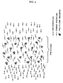
- Fig. 2 is an explanatory diagram for explaining the process for collecting ash by means of the pre-filter of the present invention. This indicates a state in which the exhaust gas is fed through the pre-filter from the left side so that the ash is trapped.
- the size of the ash in the exhaust gas has a diameter of about several tens nm and the median value thereof are about 30 nm.
- Particulate matter composed mainly of soot is finer, namely of the order of about 10 nm.
- ash can be selectively collected when the exhaust gas containing these passes through the pre-filter.
- the ash is composed mainly of CaSO 4
- its specific gravity is about 3 and its particle size is large. Since the particles are spongy and absorb the water content generated by combustion of fuel in the exhaust gas, they become sticky.
- the particulate matter composed mainly of soot its particle size is small and its specific gravity is less than 2. Although they contain some amount of undecomposed substances of hydrocarbons, they are not so sticky. If the exhaust gas containing these particles strikes skeleton of the pre-filter, gas flow is bent by the skeleton.
- the particles of the ash collide with the skeleton because of their large inertial force and adhere to the skeleton because of their sticky characteristic.
- the particles of the particulate matter follow the gas flow because their inertial force is small, and even if they collide with the skeleton, it is repelled because they are not so sticky.
- the ash is selectively trapped by the skeleton of the filter. If the pores in the pre-filter skeleton are large, a possibility that the ash does not collide with the skeleton and passes through is increased. On the contrary, if the pores in the skeleton are small, undesirably, the ash is concentrated to the surface of the pre-filter.
- the pressure drop is mainly considered for evaluation and judging from these resets it holds true.
- the thickness of the filter can be set large when the pore diameter thereof is large, while it can be set small when the pore diameter thereof is small, depending on a probability that the ash strikes the skeleton as aforementioned. Preferably, it is about 0.5 to 3.0 mm.
- Fig. 3 is a schematic view of a structure showing a particularly preferred material configuration for the pre-filter and this material is called a metal foam.
- This structure is rigid and preferable because the junctions of the skeleton structure are firmly formed. More specifically, the metal foam called "CELLMET” ®, manufactured by Sumitomo Electric Ind., Ltd. has been well known.
- Fig. 4 is a graph of data obtained by measuring pressure drop at the time of continuous high temperature durability tests conducted with respect to a filter unit which is provided with a pre-filter of the present invention and that which is not provided with a pre-filter.
- the specifications of the pre-filter and main filter and the testing method will be described in Example 1.
- the feature of the two-stage filter structure of the present invention is that a collecting object of each filter is different. Namely, the first stage pre-filter aims to collect mainly the ash and the second stage main filter aims to collect the particulate matter composed mainly of soot.
- the first stage pre-filter has a feature in its pore diameter. That is, the pore diameter of more than 80 ⁇ m to not more than 300 ⁇ m effectively collects the ash. If the pore diameter is 80 ⁇ m or less, it is too small, so that most of the ash is collected in the vicinity of the surface of the pre-filter and as a result of a long term use, the pre-filter is itself clogged. If the pore diameter exceeds 300 ⁇ m, the ash collides with the skeleton of the pre-filter so that the probability that it is not collected and passes through increases. Thus, the passing ash is collected by the main filter, so that the efficiency of the pre-filter is reduced.
- the structure of the pre-filter in this case is preferably flat so that the ash in the exhaust gas collides with the skeleton to be collected. Because this flat sheet has a plane perpendicular to a flow of the exhaust gas, the skeleton is required to be solid. Specifically, the metal foam is preferred.
- the pore diameter of the main filter can be not less than 10 ⁇ m to not more than 80 ⁇ m. It is better to select this pore diameter to collect the particulate matter composed mainly of soot in the exhaust gas whose ash has been removed by the pre-filter. If the pore diameter is less than 10 ⁇ m, the collected particulate matter are concentrated on the vicinity of the surface of the filter so that the clogging is accelerated. If the pore diameter exceeds 80 ⁇ m, fine particulate matter cannot be collected and they passes through the filter. As a result, the efficiency of the filter is reduced.
- the pore diameter of the filter is reduced, the back-pressure of the exhaust gas is increased. Therefore, it is recommendable to secure a larger filter area.
- metallic unwoven fabric and metallic corrugated sheets are stacked on each other alternately and they are wound spirally, and the exhaust gas inlet side and outlet side are sealed alternately.
- the exhaust gas flow and filter surface are placed in parallel to each other. Therefore, the exhaust gas does not strike the filter surface at a right angle but passes through the filter diagonally.
- the effective pore diameter of the filter is further reduced, so that the collecting accuracy is improved.
- a diameter of an inscribed circle of each of at least 50 fine pores is measured by a scanning electron microscope (SEM) and an average value is expressed.
- the pre-filter and main filter are preferably made of metal.
- the metallic structure has an advantage that a temperature of the exhaust gas is transmitted to fine sections easily so that it is not likely to be damaged by crack or crevice which may be caused by distortion due to thermal expansion.
- the metallic composition of the pre-filter is preferably composed of 15 to 40 wt.% of Cr, 1 to 15 wt.% of Al and the balance being either Fe or Ni or both of them with unavoidable impurities.
- the main filter is preferably composed of 15 to 40 wt.% of Cr, 1 to 8 wt.% of Al and the balance being either Fe or Ni or both of them with unavoidable impurities.
- the optimum composition of the pre-filter and main filter should preferably be different each other because the matter to be collected by the respective filters are different. Both the compositions are determined from the viewpoint of thermal resistance and corrosion resistance, rather than processing characteristic. Since the pressure of a high Al content makes the material hard, it is preferable to form a stainless steel, Fe-Ni alloy, Fe or Ni metallic body into a filter shape and then incorporate Cr, Al into the shaped material by diffusion alloying method.
- the filter of the present invention can be used for a long time. Further, by loading part or the whole of the surface of the pre-filter and main filter with a platinum-family catalyst, harmful gas components in the exhaust gas also can be reduced.
- the platinum family mentioned here refers to platinum, palladium, rhodium and iridium. Unlike the conventional methods to purify the gas,by loading the filter surface with a catalyst according to the present invention, the contact between the catalyst and the exhaust gas is improved, and the conversion efficiency is also improved.
- the pre-filter may be comprised of two sheets such that one on the exhaust gas inlet side is not loaded with the catalyst while the other on the exhaust gas emission side is loaded with the catalyst, or the main filter may be composed of two layers such that only the layer on the exhaust gas emission side is loaded with a catalyst, because if the ash is accumulated on the pre-filter on the exhaust gas inlet side or if the remaining particulate matter is accumulated on the main filter on the exhaust gas inlet side, the conversion efficiency is thereby decreased. Thus, an excellent catalyzing effect can be obtained, thereby improving economic performance.
- the corrugated sheet for use as a separator in the main filter may be bored to secure a light weight or made of metal foam, such as one used for the pre-filter.
- the particulate traps for a diesel engine according to the present invention are not clogged so much despite a long term use and not affected by a back-pressure to an engine, so that it is preferable for practical use.
- Unwoven fabrics 0.5 mm thick composed of short fibers 15 ⁇ m in diameter made of stainless steel (SUS316: Cr 17 wt.%, Ni 14 wt.%, with Fe and impurities) and corrugated sheets which were 0.1 mm thick Fe-Cr alloy sheets subjected to corrugating processing at a pitch of 1 mm and at an amplitude of 0.7 mm, were alternately stacked over each other and wound spirally.
- the two sheets of the unwoven fabrics and two corrugated sheets were used to form a main filter.
- the end portions of either side of the unwoven fabrics were welded and sealed together alternately to form a spiral bag as viewed from either side thereof.
- the composition of the main filter was adjusted by diffusion alloying method (calorizing or chromizing) to consist of 25 wt.% of Cr, 5 wt.% of Al, 12 wt.% of Ni with the balance being Fe and impurities.
- the corrugated sheet was transformed by the diffusion alloying method to have a composition consisting of 20 wt.% of Cr, 5 wt.% of Al with the balance being Fe and impurities.
- This filter was used as the main filter A. As for sizes thereof, its length was 150 mm and its diameter was 80 mm. This was put into a stainless cylinder having an internal diameter of 82 mm and both ends of the filter were welded to the cylinder. The 5 mm length at one end of the stainless cylinder was reserved for a pre-filter to be installed therein. The average pore diameter of the filter was 10 ⁇ m.
- samples having a different average pore diameter by changing the fiber diameter were produced.
- a sample produced using fiber diameter of 25 ⁇ m had an average pore diameter of 21 ⁇ m.
- This sample was used as main filter B.
- a filter produced by using fiber diameter of 50 ⁇ m had an average pore diameter of 60 ⁇ m. This filter was used as main filter C.
- pre-filter pore diameter ( ⁇ m) main filter type 50 80 100 200 500 1000 2000 no pre-filter A (10 ⁇ m) 36 14 13 12 11 10 10 10 B (21 ⁇ m) 35 11 10 9 9 9 8 8 C (60 ⁇ m) 33 9 8 8 8 7 7 7 data after test Pre-fifter pore diameter ( ⁇ m) main filter type 50 80 100 200 500 1000 2000 no pre-filter A (10 ⁇ m) 158 52 46 34 82 80 77 76 B (21 ⁇ m) 151 40 34 24 57 55 53 52 C (60 ⁇ m) 132 30 24 20 51 50 48 48
- a graph shown in Fig. 4 traces data of test 1 (using main filter A without the pre-filter) and test 3 (using main filter A in combination with the pre-filter having a pore diameter of 100 ⁇ m) in Example 1 with the passage of time.
- the pressure drop of test 1 was smaller than test 3 at the initial stage of the test because the pre-filter was not provided. However, the pressure drop of test 1 became larger than that of test 3 as the test was progressed. Namely, in the case of test 1, part of the particulate matter collected by the main filter could not be removed by burning and was accumulated to increase the pressure drop. On the contrary, in the case of test 3, the cause for the clogging to affect the pressure drop was removed by the use of the pre-filter having a relatively large pore diameter. Therefore, the increase of the pressure drop could be suppressed.
- a filter having the same specification as filter B (pore diameter of 21 ⁇ m) used in Example 1 was used as the main filter.
- the pre-filters were of the same specification as used in Example 1 having a pore diameter of 100 ⁇ m, their metallic compositions were varied by changing the diffusion alloying conditions so that the pre-filter had the compositions shown in Table 2.
- Example 2 the continuous high temperature durability test was conducted using the exhaust gas from a diesel engine. Each pre-filter was observed every 100 hours and the test was continued for 300 hours. If there was no abnormal change in its external appearance, it was judged as "excellent”. Table 2 shows the test results on the external changes.
- composition of pre-filter wt.% continuous high temperature durability test (Hrs) Cr Al balance 100 200 300 20 0 Ni, unavoidable component excellent corrosion corrosion 21 10 " excellent excellent excellent 22 18 " excellent excellent damage 10 6 " corrosion corrosion and damage serious corrosion and damage 30 5 " excellent excellent excellent 44 4 " excellent excellent damage
- the particulate trap for a diesel engine in which the pre-filter having a pore diameter of 100 ⁇ m and the main filter B (21 ⁇ m in pore diameter), both used in Example 1, were combined, was prepared.
- a catalyst was applied thereto.
- dinitrodiamine platinum nitrate containing platinum of 33g/liter was dissolved in deionized water to prepare an aqueous solution and then alumina powder of 1 kg having a specific surface area of 120 m 2 /g was charged into this solution and agitated sufficiently.
- the resultant mixture was dried for two hours at 150°C and further baked for two hours at 250°C so as to produce alumina powder on which platinum was dispersion-loaded. Further, the resultant alumina powder was subjected to wet grinding to obtain an alumina slurry.
- the alumina slurry was applied to the aforementioned particulate trap and an excessive slurry was removed, and then it was dried for two hours at 150°C. Further, it was baked for an hour at 500°C so as to load the entire surface of the particulate trap with the catalyst.
- the loading amount was 30 g for alumina and 2g for platinum with respect to 1 liter of the particulate trap structure.
- the particulate trap loaded with the catalyst was subjected to the same continuous high temperature durability test as Example 1 and pressure drops before and after this were measured. As a result, the value before the test was 12 kPa and the value after the test was 35 kPa, indicating that it was in an excellent range.
- the odor of the exhaust gas was removed. That is, the use of the catalyst is effective in removing the odor of the exhaust gas.
- the pre-filter according to the present invention As described above, with the pre-filter according to the present invention, a rise of back-pressure of the exhaust gas due to the clogging of the main filter is suppressed so that a long service life of the filter can be attained. As a result, a practically advantageous particulate filter can be provided. Further, by loading the surface of these filters with a catalyst, there is produced an effect of reducing the odor in the exhaust gas.
Landscapes
- Engineering & Computer Science (AREA)
- Chemical & Material Sciences (AREA)
- Chemical Kinetics & Catalysis (AREA)
- General Engineering & Computer Science (AREA)
- Combustion & Propulsion (AREA)
- Mechanical Engineering (AREA)
- Toxicology (AREA)
- Health & Medical Sciences (AREA)
- Inorganic Chemistry (AREA)
- Geology (AREA)
- Life Sciences & Earth Sciences (AREA)
- Filtering Materials (AREA)
- Processes For Solid Components From Exhaust (AREA)
- Filtering Of Dispersed Particles In Gases (AREA)
- Exhaust Gas Treatment By Means Of Catalyst (AREA)
- Exhaust Gas After Treatment (AREA)
Claims (7)
- Partikelabscheider für einen Dieselmotor, wobei der Abscheider umfasst: einen Metall-Hauptfilter mit einem durchschnittlichen Porendurchmesser von 10 µm bis 80 µm und einem Metall-Vorfilter mit einem durchschnittlichen Porendurchmesser von mehr als 80 µm, aber nicht mehr als 300 µm, wobei die Oberfläche des Hauptfilters während des Gebrauchs parallel zu einem Abgasstrom angeordnet ist und der Vorfilter in einer flachen Platte ausgeformt ist und während des Gebrauchs senkrecht zum Gasstrom angeordnet ist.
- Partikelabscheider gemäß Anspruch 1, wobei der Vorfilter aus einem Metallschwamm besteht.
- Partikelabscheider gemäß Anspruch 1 oder Anspruch 2, wobei der Hauptfilter spiralförmig aufgebaut ist und aus ungewebten Metallgazen besteht, wobei sich ein Wellblech zwischen den Schichten der ungewebten Metallgaze befindet, während die ungewebten Metallgaze alternierend entweder einen Abgas-Einlassabschnitt oder einen Abgas-Auslassabschnitt verschließen.
- Partikelabscheider gemäß einem der Ansprüche 1 bis 3, wobei der Vorfilter aus 15 bis 40 Gew.-% Cr, 1 bis 15 Gew.-% Al und dem Rest, bestehend aus entweder Fe oder Ni oder aus beidem und unvermeidbaren Verunreinigungen, zusammengesetzt ist.
- Partikelabscheider gemäß einem der Ansprüche 1 bis 4, wobei der Hauptfilter aus 15 bis 40 Gew.-% Cr, aus 1 bis 8 Gew.-% Al und dem Rest, bestehend aus entweder Fe oder Ni oder aus beidem und unvermeidbaren Verunreinigungen, zusammengesetzt ist.
- Partikelabscheider gemäß einem der Ansprüche 1 bis 5, wobei ein Teil oder der gesamte Hauptfilter und/oder Vorfilter mit einem Katalysatormaterial gefüllt ist/sind, welches ein Metall der Platingruppe umfasst bzw. aus diesem besteht.
- Abgassystem für einen Dieselmotor mit einem Partikelabscheider gemäß einem der Ansprüche 1 bis 6.
Applications Claiming Priority (2)
| Application Number | Priority Date | Filing Date | Title |
|---|---|---|---|
| JP13186298A JP3462750B2 (ja) | 1998-05-14 | 1998-05-14 | ディーゼルエンジン用パティキュレートトラップ |
| JP13186298 | 1998-05-14 |
Publications (3)
| Publication Number | Publication Date |
|---|---|
| EP0957241A2 EP0957241A2 (de) | 1999-11-17 |
| EP0957241A3 EP0957241A3 (de) | 2003-07-23 |
| EP0957241B1 true EP0957241B1 (de) | 2004-11-10 |
Family
ID=15067871
Family Applications (1)
| Application Number | Title | Priority Date | Filing Date |
|---|---|---|---|
| EP99303728A Expired - Lifetime EP0957241B1 (de) | 1998-05-14 | 1999-05-13 | Partikelfalle für einen Dieselmotor |
Country Status (3)
| Country | Link |
|---|---|
| EP (1) | EP0957241B1 (de) |
| JP (1) | JP3462750B2 (de) |
| DE (1) | DE69921731T2 (de) |
Families Citing this family (13)
| Publication number | Priority date | Publication date | Assignee | Title |
|---|---|---|---|---|
| JP2001073742A (ja) * | 1999-06-29 | 2001-03-21 | Sumitomo Electric Ind Ltd | ディーゼルエンジン用パティキュレートトラップ |
| EP1186748A1 (de) * | 2000-09-05 | 2002-03-13 | Siemens Aktiengesellschaft | Laufschaufel für eine Strömungsmaschine sowie Strömungsmaschine |
| JP2002146659A (ja) * | 2000-11-07 | 2002-05-22 | Sumitomo Electric Ind Ltd | 金属不織布及びその製造方法 |
| US6770252B2 (en) * | 2001-11-21 | 2004-08-03 | General Motors Corporation | Rolling regeneration diesel particulate trap |
| DE10235766A1 (de) * | 2002-08-02 | 2004-02-19 | Emitec Gesellschaft Für Emissionstechnologie Mbh | Abgasfilter und Verfahren zum Reinigen eines Abgases |
| GB0226726D0 (en) * | 2002-11-15 | 2002-12-24 | Bp Oil Int | Method |
| DE10254661A1 (de) * | 2002-11-22 | 2004-06-09 | Umicore Ag & Co.Kg | Verfahren zur Beschichtung eines Katalysatorträgers enthaltend zwei unterschiedliche Teilstrukturen mit einer katalytisch aktiven Beschichtung und dadurch erhaltener Katalysator |
| JP2006526726A (ja) * | 2003-04-24 | 2006-11-24 | ビーワイディー カンパニー リミテッド | マフラー及び触媒コンバーター装置 |
| JP2006144689A (ja) * | 2004-11-22 | 2006-06-08 | Babcock Hitachi Kk | 排ガス浄化装置 |
| US7506504B2 (en) * | 2005-12-21 | 2009-03-24 | Basf Catalysts Llc | DOC and particulate control system for diesel engines |
| AT504391B1 (de) * | 2006-11-13 | 2008-12-15 | Pankl Emission Control Systems | Kombiniertes abgasreinigungssystem |
| JP2009072764A (ja) * | 2007-09-21 | 2009-04-09 | Waertsilae Schweiz Ag | 排気ガス粒子用フィルター、および排気ガス粒子用フィルターの製造方法 |
| US9724635B2 (en) * | 2013-03-14 | 2017-08-08 | Bladwin Filters, Inc. | Rectangular stacked fluted filter cartridge |
Family Cites Families (11)
| Publication number | Priority date | Publication date | Assignee | Title |
|---|---|---|---|---|
| CH462783A (de) * | 1968-05-16 | 1968-09-30 | Bopp & Co G | Filterkörper aus Metallfasern |
| CA1094957A (en) * | 1976-04-23 | 1981-02-03 | Harry M. Kennard | Filter medium |
| JP2624335B2 (ja) | 1989-06-19 | 1997-06-25 | 松下電子工業株式会社 | レジスト露光方法 |
| DE4141580A1 (de) * | 1991-12-17 | 1993-06-24 | Didier Werke Ag | Partikelfilter |
| JPH06257422A (ja) | 1993-01-06 | 1994-09-13 | Sumitomo Electric Ind Ltd | ディーゼルエンジン用パティキュレートトラップ |
| JPH06294313A (ja) | 1993-03-18 | 1994-10-21 | Sumitomo Electric Ind Ltd | 排気ガス浄化用トラップ |
| JP2870369B2 (ja) | 1993-06-18 | 1999-03-17 | 住友電気工業株式会社 | 排気ガス浄化用フィルター |
| JP3265737B2 (ja) | 1993-08-20 | 2002-03-18 | 住友電気工業株式会社 | 高耐食性金属フィルタ |
| JP3288536B2 (ja) * | 1994-06-21 | 2002-06-04 | 日本碍子株式会社 | 排ガスフィルタおよびそれを使用した排ガス処理装置 |
| DE19611150A1 (de) * | 1996-03-21 | 1997-05-28 | Mtu Friedrichshafen Gmbh | Partikelfilter für eine Brennkraftmaschine |
| JP3434117B2 (ja) * | 1996-03-29 | 2003-08-04 | 住友電気工業株式会社 | ディーゼルエンジン用パティキュレートトラップ |
-
1998
- 1998-05-14 JP JP13186298A patent/JP3462750B2/ja not_active Expired - Fee Related
-
1999
- 1999-05-13 EP EP99303728A patent/EP0957241B1/de not_active Expired - Lifetime
- 1999-05-13 DE DE69921731T patent/DE69921731T2/de not_active Expired - Fee Related
Also Published As
| Publication number | Publication date |
|---|---|
| DE69921731D1 (de) | 2004-12-16 |
| JPH11324645A (ja) | 1999-11-26 |
| DE69921731T2 (de) | 2005-03-31 |
| EP0957241A2 (de) | 1999-11-17 |
| JP3462750B2 (ja) | 2003-11-05 |
| EP0957241A3 (de) | 2003-07-23 |
Similar Documents
| Publication | Publication Date | Title |
|---|---|---|
| JP3434117B2 (ja) | ディーゼルエンジン用パティキュレートトラップ | |
| EP0603392B1 (de) | Partikelfilter zur reinigung von dieselmotorabgas | |
| EP0747579B1 (de) | Partikelfalle für einen Dieselmotor | |
| EP1599660B1 (de) | Dieselmotor mit katalysiertem filter | |
| EP3842142B1 (de) | Abgasreinigungskatalysator | |
| EP0707139A1 (de) | Partikelfilter | |
| EP0957241A2 (de) | Partikelfalle für einen Dieselmotor | |
| JP3378432B2 (ja) | ディーゼルエンジン用パティキュレートトラップ | |
| EP1251247B1 (de) | Filter zum Reinigen von Abgas | |
| EP0630676A1 (de) | Filter zur Reinigung von Abgasen und Filtermedium dafür | |
| CA2312609A1 (en) | Particulate trap for diesel engines | |
| US8092565B2 (en) | Particulate filter | |
| US20050223688A1 (en) | Filter medium | |
| JP2010517743A (ja) | 波形の壁を備えたガス濾過構造体 | |
| EP2035663A1 (de) | Teilchenfilter | |
| US11759747B2 (en) | Metal foil catalyst for the control of emissions from diesel engines | |
| RU2476693C2 (ru) | Фильтр из металлических волокон для очистки выхлопного газа, имеющий перепускную часть щелевого типа | |
| JP3207088B2 (ja) | ディーゼルエンジン用パティキュレートトラップ | |
| KR20070000043A (ko) | 디젤엔진의 입자상물질 제거용 필터장치 | |
| US11473472B2 (en) | Exhaust gas control apparatus and manufacturing method thereof | |
| JP5526388B2 (ja) | 排ガス浄化フィルターおよび排ガス浄化装置 | |
| JP4293771B2 (ja) | ハニカムフィルター | |
| JPH09262415A (ja) | ディーゼルエンジン用パティキュレートトラップ | |
| JPH1162552A (ja) | 排気ガス浄化装置 | |
| KR20050046710A (ko) | 디젤 엔진 및 촉매 컨버터를 포함하는 기계동력 발전기 |
Legal Events
| Date | Code | Title | Description |
|---|---|---|---|
| PUAI | Public reference made under article 153(3) epc to a published international application that has entered the european phase |
Free format text: ORIGINAL CODE: 0009012 |
|
| AK | Designated contracting states |
Kind code of ref document: A2 Designated state(s): AT BE CH CY DE DK ES FI FR GB GR IE IT LI LU MC NL PT SE |
|
| AX | Request for extension of the european patent |
Free format text: AL;LT;LV;MK;RO;SI |
|
| PUAL | Search report despatched |
Free format text: ORIGINAL CODE: 0009013 |
|
| AK | Designated contracting states |
Designated state(s): AT BE CH CY DE DK ES FI FR GB GR IE IT LI LU MC NL PT SE |
|
| AX | Request for extension of the european patent |
Extension state: AL LT LV MK RO SI |
|
| RIC1 | Information provided on ipc code assigned before grant |
Ipc: 7B 01D 39/20 B Ipc: 7F 01N 3/28 B Ipc: 7F 01N 3/02 A |
|
| RAP1 | Party data changed (applicant data changed or rights of an application transferred) |
Owner name: TOYOTA JIDOSHA KABUSHIKI KAISHA Owner name: SUMITOMO ELECTRIC INDUSTRIES, LTD. |
|
| 17P | Request for examination filed |
Effective date: 20031016 |
|
| 17Q | First examination report despatched |
Effective date: 20031119 |
|
| AKX | Designation fees paid |
Designated state(s): DE FR GB IT |
|
| GRAP | Despatch of communication of intention to grant a patent |
Free format text: ORIGINAL CODE: EPIDOSNIGR1 |
|
| GRAS | Grant fee paid |
Free format text: ORIGINAL CODE: EPIDOSNIGR3 |
|
| GRAA | (expected) grant |
Free format text: ORIGINAL CODE: 0009210 |
|
| AK | Designated contracting states |
Kind code of ref document: B1 Designated state(s): DE FR GB IT |
|
| REG | Reference to a national code |
Ref country code: GB Ref legal event code: FG4D |
|
| REG | Reference to a national code |
Ref country code: IE Ref legal event code: FG4D |
|
| REF | Corresponds to: |
Ref document number: 69921731 Country of ref document: DE Date of ref document: 20041216 Kind code of ref document: P |
|
| PLBE | No opposition filed within time limit |
Free format text: ORIGINAL CODE: 0009261 |
|
| STAA | Information on the status of an ep patent application or granted ep patent |
Free format text: STATUS: NO OPPOSITION FILED WITHIN TIME LIMIT |
|
| ET | Fr: translation filed | ||
| 26N | No opposition filed |
Effective date: 20050811 |
|
| PGFP | Annual fee paid to national office [announced via postgrant information from national office to epo] |
Ref country code: DE Payment date: 20080522 Year of fee payment: 10 |
|
| PGFP | Annual fee paid to national office [announced via postgrant information from national office to epo] |
Ref country code: IT Payment date: 20080529 Year of fee payment: 10 |
|
| PGFP | Annual fee paid to national office [announced via postgrant information from national office to epo] |
Ref country code: GB Payment date: 20080514 Year of fee payment: 10 |
|
| GBPC | Gb: european patent ceased through non-payment of renewal fee |
Effective date: 20090513 |
|
| REG | Reference to a national code |
Ref country code: FR Ref legal event code: ST Effective date: 20100129 |
|
| PG25 | Lapsed in a contracting state [announced via postgrant information from national office to epo] |
Ref country code: FR Free format text: LAPSE BECAUSE OF NON-PAYMENT OF DUE FEES Effective date: 20090602 |
|
| PGFP | Annual fee paid to national office [announced via postgrant information from national office to epo] |
Ref country code: FR Payment date: 20080514 Year of fee payment: 10 |
|
| PG25 | Lapsed in a contracting state [announced via postgrant information from national office to epo] |
Ref country code: GB Free format text: LAPSE BECAUSE OF NON-PAYMENT OF DUE FEES Effective date: 20090513 |
|
| PG25 | Lapsed in a contracting state [announced via postgrant information from national office to epo] |
Ref country code: DE Free format text: LAPSE BECAUSE OF NON-PAYMENT OF DUE FEES Effective date: 20091201 |
|
| PG25 | Lapsed in a contracting state [announced via postgrant information from national office to epo] |
Ref country code: IT Free format text: LAPSE BECAUSE OF NON-PAYMENT OF DUE FEES Effective date: 20090513 |