EP0956231B1 - Surface de chargement pour vehicule utilitaire - Google Patents
Surface de chargement pour vehicule utilitaire Download PDFInfo
- Publication number
- EP0956231B1 EP0956231B1 EP98900063A EP98900063A EP0956231B1 EP 0956231 B1 EP0956231 B1 EP 0956231B1 EP 98900063 A EP98900063 A EP 98900063A EP 98900063 A EP98900063 A EP 98900063A EP 0956231 B1 EP0956231 B1 EP 0956231B1
- Authority
- EP
- European Patent Office
- Prior art keywords
- loading surface
- profile
- extruded
- surface according
- butt joint
- Prior art date
- Legal status (The legal status is an assumption and is not a legal conclusion. Google has not performed a legal analysis and makes no representation as to the accuracy of the status listed.)
- Expired - Lifetime
Links
Images

Classifications
-
- B—PERFORMING OPERATIONS; TRANSPORTING
- B60—VEHICLES IN GENERAL
- B60P—VEHICLES ADAPTED FOR LOAD TRANSPORTATION OR TO TRANSPORT, TO CARRY, OR TO COMPRISE SPECIAL LOADS OR OBJECTS
- B60P7/00—Securing or covering of load on vehicles
- B60P7/06—Securing of load
- B60P7/08—Securing to the vehicle floor or sides
- B60P7/0884—Securing to the vehicle floor or sides by increasing the friction between the load and the surface
-
- B—PERFORMING OPERATIONS; TRANSPORTING
- B62—LAND VEHICLES FOR TRAVELLING OTHERWISE THAN ON RAILS
- B62D—MOTOR VEHICLES; TRAILERS
- B62D25/00—Superstructure or monocoque structure sub-units; Parts or details thereof not otherwise provided for
- B62D25/20—Floors or bottom sub-units
- B62D25/2054—Load carrying floors for commercial vehicles
Definitions
- the invention relates to a loading area for a commercial vehicle according to the preamble of claim 1.
- the loading area of commercial vehicles is known to be able to Checker plates or barley grain plates equipped as a base plate become. Strip-shaped sheets of this type are welded together, i.e. thermally connected to the disadvantages known from thermal connections.
- the generic DE 42 43 093 A1 describes a profile floor for commercial vehicles with a load-bearing base, as well as flat on it applied individual, interconnected the surface profiled plate elements, which by means of a special nose / cam device on their parallel Outer edges in horizontal and vertical directions against each other can be pre-fixed.
- the final setting the plate elements are made by gluing the plate elements with the ground floor.
- the goal is to create a low-cost loading area or a base plate to offer for a loading area which is not is changed by thermal welding and beyond Light weight, non-slip, joint-proof and weatherproof is.
- the loading area spans it Extruded aluminum alloy profiles, the are firmly connected to each other in a non-thermal way as well as the one that detects at least two of the extruded profiles - Form the base plate. It has proven to be cheap the extruded profiles of the base plate with the loading area as well as glue together. This creates an extraordinary lightweight base plate, which is also quiet, independent of tolerance, non-slip, joint-proof and weatherproof is - provided that the latter Property also come to the glue.
- the base plate is advantageously made of several extruded profiles composed, two of which are adjacent form a butt joint closed to the floor, the is overlaid with an adhesive layer.
- This block-like adhesive layer is made of a solvent and plasticizer-free elastic material Two component base manufactured.
- a cross-sectionally L-shaped extruded profile from one legs and legs integrated into the base plate when installed one leg assigned to the inner surface of the drop side intended.
- the adhesive described is applied to the loading area, then the ones that form the base plate Extruded profiles including the L-shaped edge profiles laid in the direction of travel on the bed so that that built-in tub forms.
- the extruded profiles are additional connected with each other.
- This material becomes more fluid Form applied in the joint area of the extruded profiles, see above that it can fill the butt joints mentioned.
- the material can be both poured and sprayed. To increase To prevent slipping, granules can be sprinkled in afterwards which are then partially removed from the surface of the adhesive layer protrude.
- the extruded profile on its lower surface facing away from the forming grooves this molded baseboards and the profile lower surface running between two base strips in Distance to the lower surfaces of the base strips is. This results in between those on the cargo bed seated baseboards a flat cavity, which itself with the glue. This too contributes to low noise the construction.
- the extruded profile a web-like connecting tongue along a long side to be molded in the installation position in a shoulder-like molding on the lower profile surface of the neighboring one Extruded profile engages and forms the bottom of the butt joint. This requirement separates the two different adhesive layers from each other and allows in the butt groove a spring-shaped between two parallel extruded profiles Install adhesive layer.
- An intermediate profile in this regard according to the invention is cross-sectionally on both sides with the described Edge indentations and can for example the short leg having the connecting tongue of the L-shaped extruded profile with the connecting tongue another floor profile.
- a trough-like built-in floor 16 made of a base plate 18 and right-angled side scouring flanks 20 recognizable, which are on the inner surfaces of the protruding on both sides of the loading area or the box floor 12 Support side walls or box walls 14.
- the scouring flank 20 of FIGS. 2, 3 of a height a of, for example 270 mm is the longer leg of an extruded profile 22 L-shaped cross section made of an aluminum alloy, whose short leg 24 has an effective width b of about 47.5 mm and that with a connecting tongue 26 of length e of 8 mm ends.
- This short leg 24 a maximum profile thickness f of 6 mm lies with base strips 28 of the free height h of 1.5 mm on the box floor 12 so that between the base strips 28, the lower profile surface 30 at a distance h from the lower surfaces 29 of the base strip 28 or to the box bottom 12.
- That connecting tongue 26 is part a base strip 28, so is the box bottom in the installed position 12 on.
- the long leg or the scouring flank 20 of this extruded profile 22 shows in Fig. 2, 3 on its inner surface three thickenings as strip-like formations 38, of which the lower two are each equipped with an external groove 32 a as a possible separation point.
- the last height g measures about 21 mm, the distance m between adjacent formations 38 here 46.5 mm.
- the thickness n 1 of the formations 38 corresponds to the aforementioned maximum width n of the shaping grooves 32, the wall thickness f 1 of the narrow profile sections running between the formations 38 being 2.5 mm here.
- the free end 21 of the long leg 20 of the extruded profile 22 offers one that is inclined downwards towards the inside of the box Desk surface 40, which in the installed position has a smooth transition to the inner surface of the box wall 14 results.
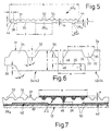
- the connecting tongue 26 of an extruded profile 22, 42nd engages in a step-shaped edge indentation 44 - the Width c of 6.5 mm - the adjacent profile 42; between two adjacent extruded profiles 22, 42 creates a butt joint above the connecting tongue 26 46 of the width t of about 1.5 mm, the Fig. 6 between opposing joint walls 48 of the extruded profiles 22, 42 can be easily recognized.
- Fig. 5 shows another profile 42 a with a width q of here 107 mm again with only one base bar 28 a with a width y.
- This profile 42 a has a bottom-side edge recess 44 on both sides, so it is intended as an intermediate piece between two profile ends with a connecting tongue 26.
- the profile 42 a formed from AlMgSi0.5 F25 offers, for example, the following cross-sectional values: F 4.39 cm2 Weight 1,186 kg / m Among other things 25.29 cm Ix .09 cm4 Iy 38.16 cm4 Wx .28 cm3 Wy 7.13 cm3 Bxm -.32 cm Eym 5.35 cm
- an adhesive 50 is first applied to the box base 12, then the extruded profiles 22, 42, 42 a - including the abrasive flanks 20 - are laid in the direction of travel so that the installation trough 16 shown in FIG. 1 results .
- a waterproof polyurethane system is preferred as the adhesive 50 used on a one-component basis, which is self-curing is. Its elongation at break is about 400% for one Abrasion behavior according to DIN 53516 of about 100 cm. It arises an elastic system with good mechanical strength, low abrasion and high tear and tear resistance. These are important for wear protection and sealing Properties are complemented by optimal elasticity between -40 ° C and + 110 ° C and adhesion to aluminum.
- the extruded profiles 22, 42, 42 a are connected to each other from above; the adhesive material is applied in liquid form in the joint area of the extruded profiles 22, 42, 42 a , as illustrated in FIG. 7.
- the accumulation of adhesive material designated there with 52 is cast in a cross-sectional width s and / or sprayed on; the cross-sectional width s is approximately 38 mm and encompasses two molding grooves 32 on each side of the butt joint 46, in which the adhesive layer 52 is toothed. This overlays the profile surface 31 in a layer thickness k of approximately 1 mm.
- the slip resistance of the profile surface 31 is increased by subsequently sprinkling in granules.
- the total width d of the light, joint-tight, non-slip, low-noise and weather-resistant built-in floor or built-in tray 16 can be preselected by using different extruded profiles 22, 42, 42 a .
Claims (12)
- Surface de chargement pour un véhicule utilitaire comportant des profilés extrudés enveloppants (24, 42, 42a), qui sont reliés entre eux de façon fixe selon une liaison non thermique, et une plaque de base (18), qui s'étend sur au moins deux profilés extrudés, les profilés extrudés de la plaque de base étant collés à la surface de chargement (12),
caractérisée en ce que respectivement deux profilés extrudés voisins (24, 42, 42a) forment un joint d'aboutement (46), fermé du côté du plancher et qu'une couche adhésive (52), est superposée à ce joint. - Surface de chargement selon la revendication 1, caractérisée en ce que les profilés extrudés (24, 42, 42a) possèdent des rainures moulées (32) qui s'étendent parallèlement au joint d'aboutement (46) et que la couche d'adhésif (52) s'engage au moins dans les deux rainures moulées voisines du joint d'aboutement.
- Surface de chargement selon la revendication 1 ou 2, caractérisée par un matériau élastique exempt de solvant et de plastifiant et réalisé à base de deux constituants en tant que couche d'adhésif (52) pour le joint d'aboutement (46).
- Surface de chargement selon l'une des revendications 1 à 3, caractérisée en ce que des granulés sont intégrés dans la surface de la couche d'adhésif (52).
- Surface de chargement selon l'une des revendications 1 à 4, caractérisée par un système formé de polyuréthane étanche à l'eau formé d'un seul constituant, en tant qu'adhésif (50) entre la surface de chargement (12) et la plaque de base (18).
- Surface de chargement comportant au moins une paroi latérale, qui limite latéralement cette surface, selon l'une des revendications 1 à 5, caractérisée par un profilé extrudé (22) en forme de L en coupe transversale, constitué par une branche (24), qui dans la position de montage est intégrée dans la plaque de base (18), et par une branche (20) associée à la surface intérieure de la paroi latérale (14).
- Surface de chargement selon au moins l'une des revendications 1 à 6, caractérisée par une cuvette de montage (16) collée à la surface de chargement et formée de profilés extrudés (24, 42, 42a)
- Surface de chargement selon au moins l'une des revendications 1 à 7, caractérisée en ce que le profilé extrudé (24, 42, 42a) comporte, sur sa surface intérieure tournée à l'opposé des rainures moulées (32), des barrettes de base conformées (28, 28a) et que la surface inférieure profilée (30), qui s'étend entre deux barrettes de base, est disposée à une distance (h) des surfaces inférieures (29) des barrettes de base.
- Surface de chargement selon au moins l'une des revendications 1 à 8, caractérisée en ce que sur le profilé extrudé (24, 42) est formée, le long d'un côté longitudinal, une languette de raccordement sous forme de réglette (26), qui, dans la position montée, s'engage dans une moulure en forme d'épaulement (44) formée sur le bord de la surface inférieure du profilé extrudé voisin (42, 42a) et forme le fond du joint d'aboutement (46).
- Surface de chargement selon au moins l'une des revendications 1 à 9, caractérisée par un profilé extrudé (42a) possédant une moulure de bord (44), qui en coupe transversale est prévue des deux côtés sur la surface inférieure du profilé.
- Surface de chargement selon la revendication 6 ou 7, caractérisée en ce que la branche (20), qui est associée à la paroi latérale (14), du profilé extrudé (22) comporte des lignes de séparation de consigne (32a), qui s'étendent parallèlement à l'autre branche (24).
- Surface de chargement selon la revendication 6 ou 7, caractérisée en ce que la branche (20), associée à la paroi latérale (14), du profilé extrudé (22) est équipé d'une surface d'extrémité (40) en biseau, qui est inclinée vers le bas en direction de la branche courte (24).
Applications Claiming Priority (3)
| Application Number | Priority Date | Filing Date | Title |
|---|---|---|---|
| DE19703203 | 1997-01-30 | ||
| DE19703203 | 1997-01-30 | ||
| PCT/CH1998/000005 WO1998033696A1 (fr) | 1997-01-30 | 1998-01-07 | Surface de chargement pour vehicule utilitaire |
Publications (2)
| Publication Number | Publication Date |
|---|---|
| EP0956231A1 EP0956231A1 (fr) | 1999-11-17 |
| EP0956231B1 true EP0956231B1 (fr) | 2001-11-28 |
Family
ID=7818680
Family Applications (1)
| Application Number | Title | Priority Date | Filing Date |
|---|---|---|---|
| EP98900063A Expired - Lifetime EP0956231B1 (fr) | 1997-01-30 | 1998-01-07 | Surface de chargement pour vehicule utilitaire |
Country Status (4)
| Country | Link |
|---|---|
| EP (1) | EP0956231B1 (fr) |
| AT (1) | ATE209586T1 (fr) |
| DE (2) | DE59802229D1 (fr) |
| WO (1) | WO1998033696A1 (fr) |
Families Citing this family (3)
| Publication number | Priority date | Publication date | Assignee | Title |
|---|---|---|---|---|
| DE102011001682A1 (de) * | 2011-03-31 | 2012-10-04 | Paula Mertzen Gmbh | Ladeboden mit hohem Gleitreibwert |
| EP2894063B1 (fr) * | 2014-01-10 | 2018-07-18 | Schmitz Cargobull AG | Revêtement de sol pour un plancher de véhicule utilitaire, plancher de véhicule utilitaire, véhicule utilitaire et procédé de fabrication d'un revêtement de plancher |
| US11220299B2 (en) * | 2018-02-09 | 2022-01-11 | Axel Johnson International Ab | Modular loading platform for a vehicle |
Family Cites Families (4)
| Publication number | Priority date | Publication date | Assignee | Title |
|---|---|---|---|---|
| FR1461668A (fr) * | 1965-10-26 | 1966-12-09 | Citroen Sa Andre | Camion à plancher étanche et protégé contre la corrosion |
| DE2753957C2 (de) * | 1977-12-03 | 1982-07-15 | M.A.N. Maschinenfabrik Augsburg-Nürnberg AG, 8000 München | Verband aus einem Fahrzeugrahmen und Karosserieteilen, insbesondere Bodenplatten |
| DE4243093C2 (de) | 1992-12-18 | 1997-02-06 | Europ Semi Remorques | Profilboden |
| WO1996007801A1 (fr) * | 1994-09-09 | 1996-03-14 | Barry Inman | Elements de construction |
-
1998
- 1998-01-07 WO PCT/CH1998/000005 patent/WO1998033696A1/fr active IP Right Grant
- 1998-01-07 DE DE59802229T patent/DE59802229D1/de not_active Expired - Fee Related
- 1998-01-07 EP EP98900063A patent/EP0956231B1/fr not_active Expired - Lifetime
- 1998-01-07 AT AT98900063T patent/ATE209586T1/de active
- 1998-01-27 DE DE19802807A patent/DE19802807A1/de not_active Withdrawn
Also Published As
| Publication number | Publication date |
|---|---|
| EP0956231A1 (fr) | 1999-11-17 |
| DE19802807A1 (de) | 1998-08-13 |
| WO1998033696A1 (fr) | 1998-08-06 |
| DE59802229D1 (de) | 2002-01-10 |
| ATE209586T1 (de) | 2001-12-15 |
Similar Documents
| Publication | Publication Date | Title |
|---|---|---|
| EP0622289B1 (fr) | Carrosserie pour véhicules à moteur | |
| DE19927006C2 (de) | Fußboden für Fahrzeuge, insbesondere Schienenfahrzeuge zur Personenbeförderung | |
| DE10110996B4 (de) | Wandelement für eine Ladegutsicherungsvorrichtung und Verfahren zu dessen Herstellung | |
| WO2015150248A1 (fr) | Caisse pour un véhicule ferroviaire comportant un élément support de toit conçu spécifiquement | |
| EP0956231B1 (fr) | Surface de chargement pour vehicule utilitaire | |
| EP1985485A2 (fr) | Profilé d'étanchéité flexible, en particulier pour un cadre de porte de véhicule utilitaire | |
| DE19854452B4 (de) | Zusammenfügbare Profilschienen zur Abdeckung, Überbrückung und/oder Einfassung der Ränder von Boden- und/oder Wandbelägen | |
| DE2109871C3 (de) | Eckverbindung zwischen der Deck- und Außenhautsandwicheschale eines Kunststoffbootskörpers | |
| DE3150027C2 (de) | Anordnung mit einem Dach und Seitenteil einer Karosserie verbindenden Flansch und einer auf ihm befestigten Dicht- und Abdeckleiste | |
| EP0087504B1 (fr) | Remorque pour véhicules à moteur | |
| EP2524855B1 (fr) | Structure pour un véhicule utilitaire | |
| DE102006030922A1 (de) | Kofferaufbau für ein Nutzfahrzeug | |
| EP1067070B1 (fr) | Rampe de chargement | |
| EP0958995B1 (fr) | Elément de paroi de carrosserie pour véhicule et procédé de fabrication d'un élément pareil | |
| DE202014100773U1 (de) | Verzurrschiene für die Befestigung von Ladegut | |
| EP0077875A1 (fr) | Court de squash à parois constituées de panneaux de couches de matières plastiques pressées | |
| DE2357108C3 (de) | Vorrichtung zum Überbrücken von Dehnungsfugen | |
| DE102013011451A1 (de) | Füllprofil für Bahngleise | |
| DE3115452A1 (de) | Wohnwagenaufbau | |
| DE3504657C2 (fr) | ||
| DE8528924U1 (de) | Anschlußelement für rohrförmige Bauteile | |
| DE10114077A1 (de) | Isolierung des Kühlraumes von Kühltransportfahrzeugen | |
| DE102006053300A1 (de) | Sandwichbauteil | |
| DE8103178U1 (de) | Wohnwagenaufbau | |
| DE202009010195U1 (de) | Kantenprofilsystem für einen Wohnwagen o.dgl. |
Legal Events
| Date | Code | Title | Description |
|---|---|---|---|
| PUAI | Public reference made under article 153(3) epc to a published international application that has entered the european phase |
Free format text: ORIGINAL CODE: 0009012 |
|
| 17P | Request for examination filed |
Effective date: 19990830 |
|
| AK | Designated contracting states |
Kind code of ref document: A1 Designated state(s): AT CH DE FR IT LI NL |
|
| GRAG | Despatch of communication of intention to grant |
Free format text: ORIGINAL CODE: EPIDOS AGRA |
|
| 17Q | First examination report despatched |
Effective date: 20010130 |
|
| GRAG | Despatch of communication of intention to grant |
Free format text: ORIGINAL CODE: EPIDOS AGRA |
|
| GRAH | Despatch of communication of intention to grant a patent |
Free format text: ORIGINAL CODE: EPIDOS IGRA |
|
| RBV | Designated contracting states (corrected) |
Designated state(s): AT CH DE FR IT LI NL |
|
| GRAH | Despatch of communication of intention to grant a patent |
Free format text: ORIGINAL CODE: EPIDOS IGRA |
|
| GRAA | (expected) grant |
Free format text: ORIGINAL CODE: 0009210 |
|
| RAP1 | Party data changed (applicant data changed or rights of an application transferred) |
Owner name: ALCAN TECHNOLOGY & MANAGEMENT AG |
|
| AK | Designated contracting states |
Kind code of ref document: B1 Designated state(s): AT CH DE FR IT LI NL |
|
| PG25 | Lapsed in a contracting state [announced via postgrant information from national office to epo] |
Ref country code: FR Free format text: LAPSE BECAUSE OF FAILURE TO SUBMIT A TRANSLATION OF THE DESCRIPTION OR TO PAY THE FEE WITHIN THE PRESCRIBED TIME-LIMIT Effective date: 20011128 |
|
| REF | Corresponds to: |
Ref document number: 209586 Country of ref document: AT Date of ref document: 20011215 Kind code of ref document: T |
|
| REG | Reference to a national code |
Ref country code: CH Ref legal event code: EP |
|
| PG25 | Lapsed in a contracting state [announced via postgrant information from national office to epo] |
Ref country code: AT Free format text: LAPSE BECAUSE OF NON-PAYMENT OF DUE FEES Effective date: 20020107 |
|
| REF | Corresponds to: |
Ref document number: 59802229 Country of ref document: DE Date of ref document: 20020110 |
|
| PG25 | Lapsed in a contracting state [announced via postgrant information from national office to epo] |
Ref country code: LI Free format text: LAPSE BECAUSE OF NON-PAYMENT OF DUE FEES Effective date: 20020131 Ref country code: CH Free format text: LAPSE BECAUSE OF NON-PAYMENT OF DUE FEES Effective date: 20020131 |
|
| PG25 | Lapsed in a contracting state [announced via postgrant information from national office to epo] |
Ref country code: NL Free format text: LAPSE BECAUSE OF NON-PAYMENT OF DUE FEES Effective date: 20020801 Ref country code: DE Free format text: LAPSE BECAUSE OF NON-PAYMENT OF DUE FEES Effective date: 20020801 |
|
| REG | Reference to a national code |
Ref country code: CH Ref legal event code: PL |
|
| NLV4 | Nl: lapsed or anulled due to non-payment of the annual fee |
Effective date: 20020801 |
|
| EN | Fr: translation not filed | ||
| PLBE | No opposition filed within time limit |
Free format text: ORIGINAL CODE: 0009261 |
|
| STAA | Information on the status of an ep patent application or granted ep patent |
Free format text: STATUS: NO OPPOSITION FILED WITHIN TIME LIMIT |
|
| 26N | No opposition filed | ||
| PG25 | Lapsed in a contracting state [announced via postgrant information from national office to epo] |
Ref country code: IT Free format text: LAPSE BECAUSE OF NON-PAYMENT OF DUE FEES Effective date: 20050107 |